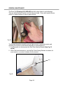
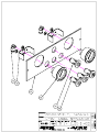
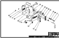
1
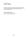
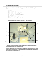
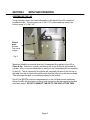
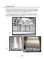
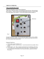
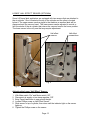
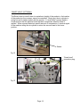
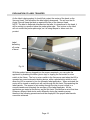
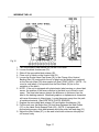
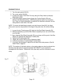
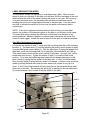
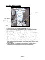
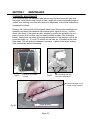
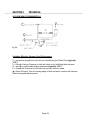
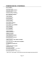
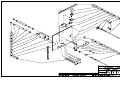
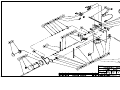
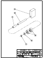
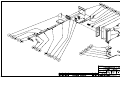
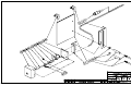
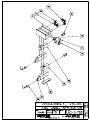
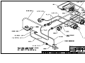
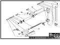
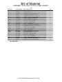
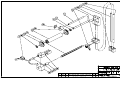
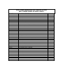
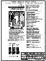
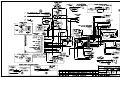
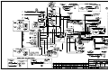
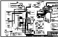
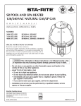
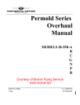
L60
Label Applier
Operator’s Manual
Serial #
Operator’s Manual
Version: D 12/18/2001
The information contained in this manual is the sole property of Universal Labeling
Systems, Inc. No parts of this manual may be reproduced or transmitted in any form
or purpose other than the purchaser’s personal use without prior consent of
Universal Labeling Systems, Inc.
Universal Labeling Systems, Inc.
3501 8th Ave South, Saint Petersburg, FL 33711
Phone (727) 327-2123 Fax (727) 323-4403
Page 2
Table of Contents
SECTION 1
OVERVIEW .................................................................................................4
INTRODUCTION......................................................................................................4
UN-PACKING INSTRUCTIONS ..............................................................................5
PRODUCT WARRANTY .........................................................................................6
SPECIFICATIONS ...................................................................................................7
SECTION 2
SETUP AND OPERATION .........................................................................8
ASSEMBLING THE L60..........................................................................................8
FUNCTION OF UNWIND ASSEMBLY....................................................................9
WASTE REMOVAL ...............................................................................................10
MOUNTING THE L-60 ...........................................................................................11
THEORY OF OPERATION....................................................................................12
LOWER “HALL EFFECT” SENSOR (OPTIONAL) ..............................................13
“SMART HEAD” (OPTIONAL) .............................................................................14
EXPLANATION OF LABEL TRANSFER..............................................................15
WEBBING THE L60 ..............................................................................................17
RUNNING THE L60 ...............................................................................................19
LABEL SENSING STAR WHEEL .........................................................................20
DATA LOGIC SENSOR (OPTIONAL) ..................................................................21
LION SENSOR (OPTIONAL) ................................................................................22
SECTION 3
MAINTENANCE ........................................................................................23
STARWHEEL MAINTENANCE.............................................................................23
GENERAL MAINTENANCE ..................................................................................24
SECTION 4
TROUBLESHOOTING ..............................................................................25
TROUBLESHOOTING (continued)......................................................................26
TROUBLESHOOTING (continued)......................................................................27
TROUBLESHOOTING (Registration) .................................................................28
SECTION 5
TECHNICAL..............................................................................................29
VACUUM HEAD FUNDAMENTALS .....................................................................29
TECHNICAL SUPPORT .....................................................................................................30
DRAWINGS AND BILL OF MATERIALS...........................................................................31
MAIN ASSEMBLY .................................................................................................31
FRONT SIDE PANEL ASSEMBLY .......................................................................31
REAR SIDE PANEL ASSEMBLY .........................................................................31
BELT TENSIONER ASSEMBLY...........................................................................31
TAMP ASSEMBLY ................................................................................................31
BLOW ASSEMBLY ...............................................................................................31
GAUGE ASSEMBLY .............................................................................................31
FRONT PANEL ASSEMBLY.................................................................................31
FRONT PANEL (PLC) ASSEMBLY......................................................................31
GUIDE ASSEMBLY...............................................................................................31
VALVE ASSEMBLY ..............................................................................................31
UNWIND ASSEMBLY ...........................................................................................31
WEBBING DIAGRAM............................................................................................31
TAMP PNEUMATIC DIAGRAM ............................................................................31
BLOW PNEUMATIC DIAGRAM ...........................................................................31
LION EYE OPTICAL LABEL SENSOR ASSEMBLY ...........................................31
DATA LOGIC OPTICAL LABEL SENSOR ASSEMBLY .....................................31
RECOMMENDED SPARE PARTS .......................................................................31
POWER MODULE SETUP SHEET .......................................................................31
ELECTRICAL DIAGRAM ......................................................................................31
ELECTRICAL DIAGRAM (PLC) ...........................................................................31
Page 3
SECTION 1
OVERVIEW
INTRODUCTION
Featuring solid-state circuitry and an AC Synchronous Motor, the L60 is a high performance,
low maintenance label applicator. The L60 applicator is designed to apply a pressure
sensitive label to a product through the action of an air-cylinder-mounted, or blow-on,
vacuum head. The labeling process can be automatic when interfaced with a conveyor, or
semi-automatic with a table-based product fixture. When triggered, the L60 Tamp vacuum
head extends to meet the product. When the air cylinder returns the vacuum head to the
home position, another label is indexed onto the head and is waiting to be applied to the
next product. The L60 BLOW vacuum head blows the label onto the product, and another
label is indexed and ready for the next product.
Switches:
There are two switches on the front panel of the applicator. The Main switch turns the
power on or off, and if a Hot Stamp Coder is used, will allow it to heat up. The Motor switch
controls the motor that turns the drive roller and waste rewind. Fig 1
Product Detection:
The product can be detected on the leading or trailing edge. To change from leading to
trailing edge, set switch 4 of the power module to the ON position. (See lower left of
Drawing L15-D-02)
Recommended Settings:
There are many different label compositions, so there is no one set of machine settings (air
pressure, etc.), which will work on all types of labels. The following recommended air
regulator settings will give the operator a place to start.
Set the air cylinder pressure to about 15 psi. The vacuum pump input pressure will vary
according to label density and size, which you can start at 5-10 psi. Turning the regulator
knobs on the side of the machine can regulate air pressures. Fig 1
Air
regulators
Switches
Fig 1
Page 4
UN-PACKING INSTRUCTIONS
When the machine is received, the shipping carton will contain the following items.
Fig 2
1.
2.
3.
4.
5.
6.
7.
8.
L-60 Body.
Unwind assembly.
Unwind assembly-backing plate.
Unwind assembly label roll retainer.
Air Fitting Part #100373 ¼ NPT x 3/8.
10’ of 3/8” hose.
Product switch in a padded envelope.
This manual in manila envelope.
Extended peeler bar assembly (OPTIONAL). See notes below. **
5
1
6
2
7
3
4
8
Fig 2
**When the machine is ordered with an extended peeler bar assembly, it will be
packed disassembled from the machine body.
Remove the machine body by placing your hands under the bottom for lifting. Refer
to the packing list, and check all packing materials to insure all of the machine parts
and accessories are accounted for.
Page 5
PRODUCT WARRANTY
Universal Labeling Systems, Inc. warranties all parts to be free from defects in
material and workmanship for a period of one year from the date of shipment from
our facility.
This guarantee is based upon equipment being used 8 hours per day, or 40 hours
per week, or in any increment which does not total more than a single shift
operation, or 2,080 hours per year. Warranty will be reduced proportionally.
This warranty does not cover parts failure caused by lack of normal maintenance,
abuse or misuse of the equipment.
PERFORMANCE GUARANTEE
All equipment manufactured by Universal Labeling Systems, Inc. carries a 30-day
performance guarantee. If your machinery does not perform as described in our
quote to you within 30 days of shipping, Universal Labeling Systems, Inc. will make
every attempt to correct it. If after a reasonable period of time, the machinery does
not meet the specified performance, we will take your machine back and reimburse
you in full.
Page 6
SPECIFICATIONS
Electrical Power:
Compressed Air:
Lubrication:
Label Apply speed:
Label Size:
Optional Wide label kit:
Standard Size:
115VAC, 3 Amps, 60Hz
Clean, Dry, 40PSI, 5CFM
The L60 label Applicator requires no lubrication
Depends on label size
4-3/8” wide on 3” Core -12” Diameter roll
6-3/8” wide on 3” Core -12” Diameter roll
19” Wide x 21” Deep x 24.75” Tall
Weight:
L60 w/ Base Plate
62 lbs (23.44 Kg)
68 lbs (25.71 Kg)
Page 7
SECTION 2
SETUP AND OPERATION
ASSEMBLING THE L60
Using a square, mount the Unwind Assembly to the back of the L60 using the 2
screws provided. The top screw is a ¼-20x1-1/2” socket head cap screw, the
bottom screw is ¼-20x1-1/4”.
Please
note:
Screws.
Top one is
longer.
Fig 3
Maximum reliability is assured when the Compressed Air supplied to the L60 is
Clean & Dry. Over time, moisture will take its toll on the Solenoid Valves and Air
cylinder. Also it is not recommended to add Oil to the Compressed Air line supplied
to the L60. The air valves and air cylinder will eventually fail and oil will end up on
the label from the Air Assist tube which helps feed the label on to the vacuum head.
This will cause the label to not adhere properly to the product.
Run 40 psi @5CFM minimum compressed air to the L60 and procure necessary
fittings to make the connection to the air inlet located on the side opposite the label
drive and rewind. DO NOT CONNECT THE AIR TO THE UNIT AT THIS TIME.
Page 8
FUNCTION OF UNWIND ASSEMBLY
The unwind is simple, but important to the operation of the L-60 machine. When the
motor starts, the web and labels are pulled through the machine by the drive roller.
The label stock pulls on the brake arm, releasing the brake, and allows the roll of
labels to unwind. When the motor stops, the brake arm returns to the rest position.
This movement tightens the brake band around the 3" diameter main unwind hub
and the roll of labels stops unwinding.
The L-60 has a fixed speed, AC drive motor that transmits power to the drive roller.
The AC drive is directly influenced by the load it is trying to pull. In this case, the load
is the tension of the brake arm spring and the weight of the roll of labels. The brake
arm spring shown below in Fig # 4, should be fastened to the unwind assembly
mounting bar in the tapped hole which provides the least amount of tension at the
brake arm. (The hole closest to the hub.)
If the L-60 is dispensing a long label (10" for example), you may have to increase
the tension on the brake arm spring (Move spring attachment point to lower hole See Fig # 4) to keep the brake arm from bottoming out.
The length and speed figures mentioned above are only examples. Your observation
of the unwind operation will be the best indication of when a tension change may be
needed.
Dancer Arm
Spring located in top
hole. Move to bottom
hole for larger labels.
Fig 4
Page 9
WASTE REMOVAL
1. To remove waste web, turn off the machine, and remove the rewind spool
clamp.
Fig 5
2. Tear the web first.
3. While holding the rewind backing plate, turn the whole waste web in the
opposite direction and pull.
Page 10
MOUNTING THE L-60
The L-60 can be mounted from the bottom or the top. The most common method is
bottom mount (see Fig 6). Fig 6 shows the L-60 mounted to the optional base plate
with standoffs. Fig 7 shows the top of an L-60 ordered with standard mounting and
can accept a coder. Fig 8 shows an L-60 Ordered for top mount.
Six holes have been provided in the two lower tie bars. Any combination may be
used. The hole pattern most used is 6-1/2" square, which is where the 4 legs are
shown in Fig. 6. All the holes are tapped 1/4-20.
Fig 6
Fig 7
Fig 8
Page 11
THEORY OF OPERATION
TAMP CYLINDER RETURN OPTIONS
Dwell Timer (Standard on all L60 Tamp Applicators)
“Dwell Time” is the time duration of the signal that opens the valve, which activates
the air cylinder. This time duration can be adjusted with the three- turn dial located
on the front panel of the machine. Turn the dial clockwise and the duration to
Dwell timer
Fig 9
increase the dwell time signal. After the label apply signal is given, the air cylinder
extends and the time duration terminates, the air cylinder then retracts and returns
the vacuum head to the home position.
Setting the Dwell time:
1. Turn the dial counter-clockwise to “0”.
2. Activate foot switch or product sensor. You will notice that the air cylinder will not
extend.
3. Turn the dial to “10”. The air cylinder should extend a short distance and return.
4. Turn the dial until the vacuum head touches the product. The dwell time is now
set. The distance of the machine from the product and air pressure will affect
this setting.
Page 12
LOWER “HALL EFFECT” SENSOR (OPTIONAL)
Some L60 tamp label applicators are equipped with two sensors that are attached to
the air cylinder. One is located at the top of the cylinder and the other is located
below it. The upper sensor sends a signal to the machine so another label will be
dispensed onto the vacuum head. The lower sensor can be adjusted to control or
limit the stroke of the air cylinder that returns the vacuum head to the home position.
The lower sensor is the only one that may require adjustment.
Hall effect
sensors.
Hall effect
connections.
Fig 11
Fig 10
Adjusting the Lower “Hall Effect” Sensor:
1.
2.
3.
4.
5.
With Main switch “On” and Motor switch “Off”.
Disconnect air supply or turn tamp regulator “Off”.
Bring Tamp Head down to new product height.
Loosen Phillips screw on Hall Effect Sensor.
Slide sensor to top of cylinder, then down until the indicator light on the sensor
lights up.
6. Tighten the Phillips screw on the sensor.
Page 13
“SMART HEAD” (OPTIONAL)
The Smart Head is used if there is a variation in height of the product or the location
of the product on the conveyor cannot be controlled. Simply put, the air cylinder is
going to travel it makes contact with the product. A “smart head“ vacuum head is
constructed so that the pad that holds the label compresses when the label is
applied. When a sensor detects a specific amount of compression, it sends a signal
to the machine telling the air cylinder to return the vacuum head to the home
position.
Sensor
Fig 12
“Smart head”
connection plug
Fig 13
Page 14
EXPLANATION OF LABEL TRANSFER
As the label is being peeled, it should first contact the center of the bevel on the
Vacuum Head. This will deflect the label slightly downward. The air from the Air
Assist Tube will keep the label up against the face of the Vacuum Head.
NOTE: The label is deflected downward so that after it is transferred to the head, it
will be resting in a position below the peeler plate edge. This is done so the label
will not contact the peeler plate edge, as it is being tamped or blown onto the
product.
Label
deflecting
off center
of bevel
Fig 14
With the product sensor plugged into the proper receptacle, you can cycle the
applicator by breaking the beam (photo eye) or tripping the foot switch or micro
switch in the fixture. The foot or micro switch in the fixture are used when the L60 is
operated as a semi-automatic labeling device, while a photoelectric switch is used
when the L60 is mounted in line for automatic label application. When activated, the
motor will be turned on and the air will rush through the Air Assist Tube assisting the
label transfer. The amount of air rushing through the tube is most critical to a
smooth transfer and ultimately the accuracy of the Label Applicator. All the
applicators are tested at the factory and the Air Assist Tube airflow is set at that time.
However, different label stocks react differently during the transfer process,
therefore, the following procedure should be employed if the proper label transfer
cannot be achieved.
Page 15
Air Assist Tube
The Air Assist (Drawing L60-I-30D #26) is a tube with a series of holes through
which air rushes assisting the transfer of the label to the Vacuum Tamp or Blow
Head. The air will rush through the tube only when the motor is running and the
label is being peeled and transferred.
Air
Assist
tube
Fig 15
It is our experience that as the roll of labels becomes smaller in diameter, some
labels tend to curl after they are peeled from the backing web. The Air Assist tube
blows the label up as it is being peeled, assisting the label onto the Vacuum Head. It
is regulated by a needle valve (Drawing L60-I-30D #28) attached to the Air
Assist Tube on the front of the machine. This air is supplied by the main incoming
line and is subject to house line pressure. Experience will tell you how much air is
needed to assist the label onto the vacuum head.
Adjusting the Air Assist Tube air pressure
1. Close the needle valve at the end of the Air Assist Tube by turning it clockwise.
2. Cycle the applicator by triggering the Product Switch Assembly.
NOTE: The label will peel, but not transfer to the head.
3. Open the needle valve by turning it counter clockwise ½ turn.
4. Repeat steps 2-3 until the label transfers onto the head with little or no deviation
from a straight-line motion.
Page 16
WEBBING THE L60
Fig 16
1.
2.
3.
4.
5.
6.
7.
8.
9.
Turn off the Main Power switch (22) on the Front Panel
Loosen the black thumbscrew (19).
Slide off the removable label retainer (20).
Place a roll of labels on the Unwind Hub (01).
Loosen the Socket Head Cap Screw (02) on the Clamp of the Unwind
Backing Disc (03) and position the roll of labels so the labels track centered
on the Vacuum Head (06) when peeled off (See FRONT VIEW). (NOTE: For
round or oval labels, it is important that the Star Wheel (05) be on the
centerline of the label).
NOTE: If the unit is equipped with photoelectric label sensing or a clear label
sensor, the position of the sensor relative to the label is not critical in most
cases. The clear label sensor detects the difference in thickness from the
label to the backing material. Metalized graphics or alphanumeric characters
will cause this sensor to false trigger. Locate the sensor away from the path
of metalized material. (See SIDE VIEW PHOTO SENSOR)
Replace the removable label retainer (20) and tighten thumbscrew (19).
Pull the web over the Brake Arm (06) and down between the Web Guides
(07) on the Label Guide Support Plate (08). (NOTE: If equipped with
photoelectric sensor, slide web between white idler roller and web drag (21).
Adjust the Web Guides (07), so the web is held with minimum side play but
still moves freely.
Page 17
10. Pull the web under the Star Wheel and down between the first Idler Roll (09)
and the Label Guide Support Plate (08), then forward over Idler Roll (10) and
under Idler Roll (11).
11. NOTE: There are 2 Web guides located here also. Adjust them as above in
Step 8.
12. Next, pull the web between the Peeler Plate (12) and the Web Drag (13).
13. Pull the web until approximately 18” extends from the peeler plate, Remove
any labels that are on this part of the web.
14. Bring the web back between the Peeler Plate (12) and Air Assist Tube (14),
under Idler Roll (10) then up around the Drive Roller (15).
15. Push the Drive Roller (15) away from the Nip Roller (16).
16. Slide the web between the Nip Roller (16) and Drive Roller (15), under the
Web Stand-Off Stud (17) then up to the Rewind Spool (18).
17. Secure the web around the Rewind Spool using Web Retention Clip (23) and
turn the Rewind Spool until the web is held firmly. This may require pulling
even more web, which will peel off some labels. Catch these labels so they
don’t stick on something.
18. Grasp the Rewind Spool and turn it counterclockwise for Right Hand, or
clockwise for Left Hand to take up slack in the web.
19. Loosen the thumbscrew on the Web Drag Assembly (13) and apply moderate
pressure by lifting up on the thumbscrew, forcing the thin Web Drag Plate
down on the labels. This will keep the label from buckling as it is fed onto the
vacuum head.
Page 18
RUNNING THE L60
1. Turn the main switch ON (01).
2. Turn motor switch ON (02).
3. Connect air supply. CAUTION: This may bring the Tamp Head up abruptly.
Keep fingers clear.
4. Cycle the machine several times (trigger the Product Switch (09)) and
observe the label web tracking. Web tracking should settle to a consistent
line. Once you have determined a consistent line has been achieved, set the
web guides on each side of the web.
NOTE: To ensure the label feeds properly onto the Vacuum Head (04), the Head
(04) must be as close as possible to the edge of the peeler bar (10), without hitting
it.
1. Loosen the two Thumbscrews (05) that hold the Star Wheel Assembly (06).
2. Slide the assembly up until the Star Wheel completely turns over and is down
on a flat side.
3. Next, slide the Star Wheel Assembly (06) up or down until the point of the Star
Wheel (07) catches the lead edge of a label (08).
4. Tighten the Thumbscrews (05).
5. Trigger the Product Switch (09) to dispense a label.
6. It may be necessary to repeat steps 5 several times.
7. It may also be necessary to adjust the air assist blow tube pressure (See Air
Assist Tube on page 9)
NOTE: The position of the label relative to the peeling edge can also be adjusted via
the three-turn dial on the front panel marked “OFF DELAY” if your machine is
equipped with this feature. Release the lock (black tab) and turn clockwise for more
delay.
Fig 17
Page 19
LABEL SENSING STAR WHEEL
The star wheel causes the applicator to stop dispensing a label. When the star
wheel is down on a flat side, it will slide over the label until the lead edge of the next
label contacts the point of the wheel causing the wheel to turn over. As it turns up
on a point and back down, the star wheel arm activates a small micro-switch
breaking the circuit, thus stopping the advance of the label web. If the star wheel
arm fails to activate the switch as it turns over the applier will dispense labels
continuously.
NOTE: If the unit is equipped with photoelectric label sensing or a clear label
sensor, the position of the sensors relative to the label is not critical in most cases.
The clear label sensor detects the difference in thickness from the label to the
backing material. Metalized graphics or alphanumeric characters will cause this
sensor to false trigger. Locate the sensor away from the path of metalized material.
Star Wheel Adjustment Procedures
Loosen the two screws (2 and 7), which hold the mounting plate (9) to the mounting
bracket (1). The screw hole (7) is slotted allowing the plate to move toward or away
from the label guide support plate (6). With the star wheel (5) laying flat against the
label web, move the mounting plate (9) in toward the label web as far as it will go.
Then slowly bring it back until the micro-switch (3) activates. (A small “click” will be
heard when this occurs). Tighten the screws (2 and 7) to hold the plate in this
position. To be sure that tightening the screws did not change the position of the
plate, check by raising the star wheel off the label web. A “click” should be heard
when the star wheel is raised and also when it is lowered. A further check should be
made by pulling the label web under the star wheel until it starts to turn up on a
point. A “click” should be heard at this point and also as the star wheel drops back
down onto a flat side. Be sure that the spring (8) is attached to the star wheel arm
(4) as this assures a firm contact of the star wheel to the label.
1
9
2
3
4
8
5
6
7
Fig 18
Page 20
DATA LOGIC SENSOR (OPTIONAL)
Auto SET button
OUT Light
READY Light
Fig 19
1. Remove one label from the liner to a get a bigger liner area.
2. Move the liner underneath the sensor cross hairs. Push and hold “Auto SET”
button until the green “READY” light turns off. Let go of the button.
3. The “READY” light will begin to flash.
4. Now move the label underneath the cross hairs. Push and hold ”AUTO SET”
button until green “Ready” light turns off. Let go of the button.
5. The “READY” light will now be on solid. The set procedure is now complete. If
you make a mistake or something went wrong, you can repeat the procedure.
6. If the sensor is set up correctly, the “OUT” light should come on in the label gap.
To make sure that it does, move the label around under the cross hairs to see if it
false detects called “hot spots” anywhere on the label.
7. If the sensor detects “hot spots” on the label, repeat steps 1-5 again. This time
when you put the label underneath the sensor put the specific “hot spot” under
the cross hairs.
8. Turning the power on or off does not affect sensitivity. Once the sensor is
programmed the values are burned into the chip inside the sensor.
Page 21
LION SENSOR (OPTIONAL)
Fig 20
Setup Procedure:
1.
2.
3.
4.
5.
Remove labels and web from inside the sensor.
Center the “Gain Adjust” by turning it four turns Counter-clockwise.
Then, turn the “Gain Adjust” back 2 turns clockwise.
Set the “Zero Adjust” to a point where the ZERO light starts to come on.
While moving labels on the web through the sensor.
Set the “Gain Adjust” to a point where the “Edge” light starts to flash.
6. Keep Turing the “Gain Adjust” ½ turn clockwise.
7. The sensor is now ready to use.
Fig 20A
Gain Adjust
Zero Adjust
Page 22
SECTION 3
MAINTENANCE
STARWHEEL MAINTENANCE
After continued use, the starwheel label sensor may become fouled with glue and
the points could become dull enough so that it might fail to catch the leading edge of
a label, thus allowing more than one label to be dispensed. It should be cleaned and
sharpened as follows:
Remove the 3 screws that hold the plastic black cover. Remove the starwheel pivot
assembly and clean the starwheel with mineral spirits, lighter fluid, etc., until the
wheel turns freely. If the points are dull, sharpen by placing the assembly flat on a
piece of crocus cloth or other very fine emery clothes or paper. (See illustration
below). Gently hone the points by moving the assembly in one direction until all the
points are sharp, i.e.. If you do 10 strokes on one side, do 10 strokes on the other
three sides. This will keep the starwheel concentric. Lightly oil the wheel, making
sure it turns freely before reinstalling.
Fig 21
Remove 3 Pan head
screws
Fig 22
Remove spring and slide
Star wheel assembly off.
Hold Index finger on top
of star to keep it steady.
Fig 23
Hone direction
Page 23
GENERAL MAINTENANCE
The Drive Roll (Drawing L60-I-00D #06) should be kept clean to avoid slippage.
This can affect the label transfer onto the Vacuum Head. Clean with lacquer thinner,
alcohol or similar cleaner to remove glue build-up.
Fig 24
The Rewind Assembly should be set just tight enough to rewind the waste web.
Adjusting the tension of the Rewind Assembly is accomplished by:
1. Loosening the nut that secures the Slip Clutch Spring Retainer (See Fig 25
below)
2. With a flat head screwdriver, turn the Slip Clutch Spring Retainer clockwise for
more tension, or counter clockwise for less tension.
Nut
Fig 25
Page 24
SECTION 4
TROUBLESHOOTING
Symptom:
Label hesitates on delivery.
Solution:
1. Drive Roll dirty. Clean with mineral spirits.
2. Idler Rollers binding. Clean and adjust if necessary.
3. Pulleys loose on shaft. Tighten carefully. Do not strip threads or Allen
wrench receptacle.
4. Drive Belt loose. Tighten Belt Tensioner Assembly.
Symptom:
Label does not always peel from backing web.
Solution:
Try increasing the Web drag tension device.
Symptom:
Label hangs up on peeler bar edge when tamping or blowing onto product.
Solution:
1. Try reducing or increasing the vacuum.
2. Check the air assist pressure.
3. Check the distance from the Vacuum head and peeler edge making sure
they are not too close.
4. Check Air supply.
5. Check Solenoid valves.
6. Make sure the Air regulators are turned on.
7. Adjust Vacuum Head. (See page 29)
Page 25
TROUBLESHOOTING (continued)
Should malfunctions occur, the following procedure should determine where the
problem is:
1. Remove label web from the machine.
2. Turn the switches “ON”.
3. Trip the product-sensing switch. The drive roll should start turning.
4. Slide the label web down under the star wheel, or (through the photo electric or
clear label sensor) until the star wheel turns up on a point and back down. The drive
roll should stop turning. If the L60 is equipped with photoelectric label sensing or a
clear label sensor, pass the label through the opening until the motor stops.
Drive Roll does not START, check the following:
1. Is the product-sensing switch plugged in side panel?
2. Is the product sensing switch malfunctioning? Check for make and break of
switch; listen for relay operation of electric eye.
3. Is the power module plugged into its receptacle securely? The power module is
found on the back of the front panel, inside the machine, and can be seen by
removing the top cover.
Drive Roll fails to STOP when star wheel turns over:
1. Remove three screws and pull off star wheel cover (See page 13). Lift up and let
down star wheel by hand; if drive roller still turns, remove spring from pin on star
wheel arm and pull Star Wheel Pivot Arm Assembly off. Activate the switch by hand.
If drive roll still turns, check for make and break with ohmmeter, and replace if
necessary.
2. Check quick disconnect connections for proper contact.
3. If Drive Roll stops when the switch is operated by hand, replace the star wheel
and adjust the star wheel assembly by loosening the two screws that hold the
backing plate and move it to a position where the star wheel will open the switch
when it turns on a point. (See page 12 for star wheel adjustment procedures).
If these adjustments fail to correct the problem, reset the power module. This can
be accomplished by removing front panel. Make sure that you ground yourself
before touching the circuit board. Static electricity can damage the board. Place
fingers on each side of circuit board. (DO NOT TOUCH ELECTRICAL
COMPONENTS ON BOARD.) Move board side to side and push down to be sure
board is seated in contacts on bottom.
Page 26
TROUBLESHOOTING (continued)
1. Is machine receiving power from power source? Check the outlet with a
voltmeter.
2. Are all electrical connections in place and tight?
3. Does motor and drive train turn freely? (Turn machine off and turn drive roll by
hand.)
4. Is machine webbed correctly? (Check webbing diagram)
5. Are drive roll and star wheel clean and operating properly?
6. Is any wiring frayed, chafed, or broken?
7. Is Belt Tensioner Assembly at correct tension? (Taunt)
8. Are adjusting screws and studs tight?
9. Are pulleys tight on shafts? Tighten set screws carefully avoid stripping threads.
And /or Allen wrench receptacle.
Page 27
TROUBLESHOOTING (Registration)
Normally, at average speeds, the Applicator will hold registration to within plus or
minus 1/32nd inch.
Variations of more than those limits are normally caused by:
Problem 1:
Label web binding.
Solution:
Check Web Guides (Drawing L60-I-60D #09 & #10) and Unwind Assembly
(Drawing UWA-13R-I-00), for proper clearance. Is peeler tape worn? (Drawing
L60-I-30D #29)
Problem 2:
Drive Roll glazed (Drawing L60-I-00D #06) and slippery or covered with labels or
glue.
Solution:
Clean with mineral spirits, lacquer thinner, alcohol, or other solvent.
Problem 3:
Drive Roll not parallel to Lower Idler Roller (Drawing L60-I-00D #06 & L60-I-10D
#05).
Solution:
Turn motor switch “off” and remove label web from Drive Roll and Idler Roller. Push
the Drive Roll away from the idler Roller and place two narrow strips of paper
between the Drive Roll and Idler Roller at each end of the drive roll. Release the
Drive Roll. The two strips, now trapped between the rolls, should have the same
“drag” when the strips are pulled in opposite directions. If not, adjustment is made
by loosening two bolts on the outside back of the machine, at the opposite end of
the Drive Roll Shaft and moving forward and back as required.
Page 28
SECTION 5
TECHNICAL
VACUUM HEAD FUNDAMENTALS
Fig 26`
Variables Affecting Vacuum Head Performance
C = as small as possible w/o the Vacuum Head hitting the Peeler Plate (typically
1/32”).
V = Enough Vacuum Pressure to hold the Label on w/o inhibiting label advance.
O = enough to deflect label slightly downward (typically 1/32”).
P = Enough Air Pressure to force label up and onto Vacuum Head.
α = Direct Air Assist Tube so Leading edge of label remains in contact with Vacuum
Head during label advancement.
Page 29
TECHNICAL SUPPORT
When calling for Technical Support:
have your Model #: L60
and the Serial Number ready (located on the side opposite the roll of labels).
Email:
[email protected]
Web Site:
http://www.universal1.com
Page 30
DRAWINGS AND BILL OF MATERIALS
MAIN ASSEMBLY
See Drawing L60-I-00D
FRONT SIDE PANEL ASSEMBLY
See Drawing L60-I-10D
REAR SIDE PANEL ASSEMBLY
See Drawing L60-I-20D or L60-I-20D1**
BELT TENSIONER ASSEMBLY
See Drawing SL1-I-20
TAMP ASSEMBLY
See Drawing L60-I-30D
BLOW ASSEMBLY
See Drawing L60-I-31D
GAUGE ASSEMBLY
See Drawing L60-I-40D
FRONT PANEL ASSEMBLY
See Drawing L60-I-50D
FRONT PANEL (PLC) ASSEMBLY
See Drawing L60-I-51D
GUIDE ASSEMBLY
See Drawing L60-I-60D
VALVE ASSEMBLY
See Drawing L60-I-70D
UNWIND ASSEMBLY
See Drawing UWA-13R-I-00
WEBBING DIAGRAM
See Drawing L60-W-00D
TAMP PNEUMATIC DIAGRAM
See Drawing L60-P-00D
BLOW PNEUMATIC DIAGRAM
See Drawing L60-P-01D
LION EYE OPTICAL LABEL SENSOR ASSEMBLY
See Drawing OLS-I-04
DATA LOGIC OPTICAL LABEL SENSOR ASSEMBLY
See Drawing OLS-I-05
RECOMMENDED SPARE PARTS
See List
POWER MODULE SETUP SHEET
See Drawing L15-D-02
ELECTRICAL DIAGRAM
See Drawing L60-E-00D or L60-E-00D1**
ELECTRICAL DIAGRAM (PLC)
See Drawing L60-E-01D or L60-E-01D1**
** Note: If your “serial number” ends with D1 then look at the drawings above that end in D1.
Page 31
Bill of Material
L60 LABEL APPLICATOR
L60
ITEM NUM:
01(D)
02(D)
02(D)
03(E)
04
04(B)
05
05(B)
06
07(D)
08(D)
08(A)(D)
09
10
11
12
13
14
15
16
17(D)
18
19
20
21
22
23
24
25
25(B)
26
27(D)
27(D)
28
29
30
31(D)
32(D)
32(C)(D)
PART NUMBER: PART DESCRIPTION:
L60-I-60D
L60-I-30D
L60-I-31D
VH-L60
L-128-C
L-128-C-A
L-128-D
L-128-D-A
L-137-D
L60-I-10D
UWA-13R-I-00
UWA-13L-I-00
100234
L60-0018A
L-154-C-02
L-153-C-02
L-152-C-02
L-108-T1
L60-1014
L60-1013
L60-I-70D
SC-006
L-139-P-2
200255
L-172-01
L-212
L-172-02
L-140-F-3
L60-0028
L60-0028-W
L-108-T
L60-I-20D
L60-I-20D1
L-155-C-02
L-114-T
L-113-T
L60-I-40D
L60-I-50D
L60-I-51D
ASSEMBLY, GUIDE
ASSEMBLY, TAMP
ASSEMBLY, BLOW
ASSEMBLY, L-60 VACUUM HEAD
CLIP, (4-1/2 WEB) RETENTION
CLIP, (6-1/2 WEB) RETENTION
SPOOL, (4-1/2 WEB) REWIND
SPOOL, (6-1/2 WEB) REWIND
ROLL, DRIVE
ASSEMBLY, FRONT SIDE PANEL
ASSEMBLY, R. H. 13" UNWIND
ASSEMBLY, L. H. 13" UNWIND
FTNG, EXHAUST MUFFLER
PANEL, BACK
COVER, TOP REAR SS
COVER, TOP CENTER SS
COVER, TOP FRONT SS
BAR, REAR ACCESSORY MOUNTING
SPACER, MOUNT
MOUNT, 4 STATION BASE
ASSEMBLY, VALVE
COLLAR, SET .376 X .62 X .250
SHAFT, REWIND
STRIP, 12 TERMINAL EURO
WASHER, ALUM. 062 x 375 x 625
BLOCK, INBOARD REWIND BEARING
WASHER, UHMW 031 X 375 X 625
COLLAR, REWIND SLIP
SHAFT, (4-1/2 WEB) DRIVE
SHAFT, (6-1/2 WEB) DRIVE
BAR, ACCESSORY MOUNTING
ASSEMBLY, REAR SIDE PANEL
ASSEMBLY, REAR SIDE PANEL
COVER, BOTTOM SS
BAR, LOWER REAR TIE
BAR, LOWER FRONT TIE
ASSEMBLY, GUAGE
ASSEMBLY, FRONT PANEL
ASSEMBLY, FRONT PANEL (PLC)
(A) = Left Hand Machine
(B) = Wide Label
(C) = PLC Models
(D) = See Drawing
(E) = Custom, Per Label Size
F:\LABELERS\L-60\MANUAL\L60-I-00D.dwg
QTY:
1
1
1
1
1
1
1
1
1
1
1
1
2
1
1
1
1
1
2
1
1
3
1
1
2
1
1
1
1
1
1
1
1
1
1
1
1
1
1
Bill of Material
ASSEMBLY, FRONT SIDE PANEL
L60
ITEM NUM:
01
02
03
03(A)
04
04(A)
05
05(A)
06
06(D)
07
08
08(A)
08(B)
08(C)
09
10
11
12
13
13(B)
14
15
16
17(F)
18(F)
18(A)(F)
19
20
21
22
23
23(E)
24
24(B)
24(E)
25
26
27
28(F)
PART NUMBER: PART DESCRIPTION:
SC-006
L-172-02
L60-0036
L60-0037
L-121-D
L-121-D-1
L-143
L-143-1
L60-0093
L60-0093S
L60-0008
L60-0007R
L60-0007RW
L60-0007L
L60-0007LW
L60-0008A
L-167
L-165
420185
L-104-FR
L-104-FL
L-172-03
L-172-04
856002
SC-006
L60-0028
L60-0028-W
L-162
200009
200011
MD-722
200028
200148
L-151-M-R
L-151-M-L
SL1-005
L-133-P
L-144-M-1
L-123-M
L-139-P-2
COLLAR, SET .376 X .62 X .250
WASHER, UHMW 031 X 375 X 625
ROLL, (4-1/2 WEB) UPPER IDLER
ROLL, (6-1/2 WEB) UPPER IDLER
STUD, (4-1/2 WEB) STAND OFF
STUD, (6-1/2 WEB) STAND OFF
ROLLER, 3" LOWER IDLER (ALUM.)
ROLLER, 6" LOWER IDLER (ALUM.)
PANEL, FRONT SIDE
PANEL, STAINLESS FRONT SIDE
BAR, COVER SUPPORT
ASS'Y, (4-1/2 WEB) RH IDLER
ASS'Y, (6-1/2 WEB) RH IDLER
ASS'Y, (4-1/2 WEB) LH IDLER
ASS'Y, (6-1/2 WEB) LH IDLER
BAR, COVER SUPPORT
BLOCK, COMP SPRING RETAINING
FOLLOWER, SPRING
SPRING,.42X1-1/2 COMP MW
ASS'Y, RIGHT PIVOT ARM
ASS'Y, LEFT PIVOT ARM
WASHER, UHMW 062 X 380 X 625
WASHER, UHMW 125 X 380 X 625
RING, 3/8" EXT. RETAINING
COLLAR, SET .376 X .62 X .250
SHAFT, (4-1/2 WEB) DRIVE
SHAFT, (6-1/2 WEB) DRIVE
SUPPORT, TOP COVER
RELAY, 12VDC 10AMP DPDT
SOCKET, 10 AMP RELAY
BRACKET, RELAY
CONNECTOR, MALE 9 PIN MOLEX
CONNECTOR, MALE 12 PIN MOLEX
BRACKET, RIGHT MOLEX CONNECTOR
BRACKET, LEFT MOLEX CONNECTOR
BRACKET, MOLEX CONNECTOR
STUD, PIVOT ARM
BLOCK, WITH BEARING
BRACKET, UNWIND MOUNTING
SHAFT, REWIND
(A) = Wide Label
(B) = Left Hand Machine
(C) = Left Hand Wide Label
(D) = Stainless Steel Machine
(E) = PLC Models
(F) = Reference Only
F:\LABELERS\L-60\MANUAL\L60-I-10D.dwg
QTY:
6
4
2
2
1
1
1
1
1
1
1
1
1
1
1
1
1
1
1
1
1
1
1
1
2
1
1
1
1
1
1
1
1
1
1
1
1
1
1
1
Bill of Material
ASSEMBLY, REAR SIDE PANEL
L60
ITEM NUM:
01(D)
02
03
04
05
06
07
08
09
10
11(D)
11(A)(D)
12
13
14
15
16
17
18
19
20
21
22
23
24
25
26(B)
27
28
29
30
31
31(C)
32
33
34
35
36
37
38
39
40
PART NUMBER: PART DESCRIPTION:
L-140-F-3
SL1-023
400010
400009
420170
L-140-F
L-140-F-1
100345
100300
100299
L60-0028
L60-0028-W
210065
300066
L60-0029B
600184
L60-0089
L60-0008
L-172-16
SC-007-1
L60-0088
100373
400165
SC-006
L-144-M-1
SL1-019
SL1-I-20
100250
100251
L60-0026
200117
L60-0094
L60-0094S
100125
L-162
200032C
200015
200019
UNIV-02
100321
100415-120
100211
COLLAR, REWIND SLIP
ASS'Y, REWIND HUB
RETAINER, 3/8" HARDENED BRNG.
BEARING, 3/8" THRUST
SPRING, .54 X 1.5 COMP. S.STL
RETAINER, SLIP CLUTCH SPRING
BLOCK, SLIP CLUTCH RETAINER
FTNG, SWVL EL 1/8 X 1/4"
REGULATOR, AIR
FTNG, 1/8" NPT BLACK PLUG
SHAFT, (4-1/2 WEB) DRIVE
SHAFT, (6-1/2 WEB) DRIVE
RELIEF, BANNER STRAIN
MOTOR, AC SYNC SUPERIOR
PULLEY, DRIVE
BELT, TIMING
ROLLER, IDLER
BAR, COVER SUPPORT
WASHER, UHMW 063 X 505 X 750
COLLAR, SET .501 X .75 X .297
MANIFOLD, AIR
FTNG, STRT 1/4 X 3/8
PULLEY, 30XLB037 TIMING
COLLAR, SET .376 X .62 X .250
BLOCK, WITH BEARING
STUD, MOTOR STAND-OFF
ASS'Y, BELT TENSIONER
FILTER, VACUUM WITH 1/4" FTGS
ELEMENT, FILTER (REPLACEMENT)
BRACKET, CAPACITOR
CAPACITOR, 15VF 370VAC
PANEL, REAR SIDE
PANEL, STAINLESS REAR SIDE
VACUUM EJECTOR W/1/4" PORTS
SUPPORT, TOP COVER
ASS'Y, PRODUCT SWITCH
AMPHENOL, 4 PIN FEMALE
AMPHENOL, 6 PIN (FEMALE)
PLATE, UNIVERSAL SERIAL NUMBER
NUT, PANEL MOUNT AIR REGULATOR
AIRLINE, 3/8" X 10'CLEAR
FTNG, 1/8 TO 1/4 STRT CONN.
(A) = Wide Label
(B) = See Drawing
(C) = Stainless Steel Machine
(D) = Reference Only
F:\LABELERS\L-60\MANUAL\L60-I-20D
QTY:
1
1
2
1
1
1
1
9
2
6
1
1
1
1
1
1
1
2
3
1
1
2
1
1
1
3
1
1
1
1
1
1
1
1
1
1
1
1
1
2
1
1
Bill of Material
ASSEMBLY, REAR SIDE
L60
ITEM NUM:
01(D)
02
03
04
05
06
07
08
09
10
11(D)
11(A)(D)
12
13
14
15
16
17
18
19
20
21
22
23
24
25
26(B)
27
28
29
30
31
31(C)
32
33
34
35
36
37
38
39
40
41
42
PART NUMBER: PART DESCRIPTION:
L-140-F-3
SL1-023
400010
400009
420170
L-140-F
L-140-F-1
100345
100300
100299
L60-0028
L60-0028-W
210065
300066-TEMP
L60-0029B
600184
L60-0089
L60-0008
L-172-16
SC-007-1
L60-0088
100373
400165
SC-006
L-144-M-1
SL1-019
SL1-I-20
100250
100251
210118
L60-0095
L60-0094
L60-0094S
100125
L-162
200032C
200015
200019
UNIV-02
100321
100415-120
100211
210119
100250-1
COLLAR, REWIND SLIP
ASS'Y, REWIND HUB
RETAINER, 3/8" HARDENED BRNG.
BEARING, 3/8" THRUST
SPRING, .54 X 1.5 COMP. S.STL
RETAINER, SLIP CLUTCH SPRING
BLOCK, SLIP CLUTCH RETAINER
FTNG, SWVL EL 1/8 X 1/4"
REGULATOR, AIR
FTNG, 1/8" NPT BLACK PLUG
SHAFT, (4-1/2 WEB) DRIVE
SHAFT, (6-1/2 WEB) DRIVE
RELIEF, BANNER STRAIN
MOTOR
PULLEY, DRIVE
BELT, TIMING
ROLLER, IDLER
BAR, COVER SUPPORT
WASHER, UHMW 063 X 505 X 750
COLLAR, SET .501 X .75 X .297
MANIFOLD, AIR
FTNG, STRT 1/4 X 3/8
PULLEY, 30XLB037 TIMING
COLLAR, SET .376 X .62 X .250
BLOCK, WITH BEARING
STUD, MOTOR STAND-OFF
ASSY. BELT TENSIONER
FILTER, VACUUM WITH 1/4" FTGS
ELEMENT, FILTER (REPLACEMENT)
RESISTOR, KIT
PLATE, CAPACITOR/RESISTOR MNT.
PANEL, REAR SIDE
PANEL, STAINLESS REAR SIDE
VACUUM EJECTOR W/1/4" PORTS
SUPPORT, TOP COVER
ASS'Y, PRODUCT SWITCH
AMPHENOL, 4 PIN FEMALE
AMPHENOL, 6 PIN (FEMALE)
PLATE, UNIVERSAL SERIAL NUMBER
NUT, PANEL MOUNT AIR REGULATOR
AIRLINE, 3/8" X 10'CLEAR
FTNG, 1/8 TO 1/4 STRT CONN.
CAPACITOR
MOUNT, FILTER
QTY:
1
1
2
1
1
1
1
9
2
6
1
1
1
1
1
1
1
2
3
1
1
2
1
1
1
3
1
1
1
1
1
1
1
1
1
1
1
1
1
2
1
1
1
1
(A) = Wide Label
(B) = See Drawing
(C) = Stainless Steel Machine
(D) = Reference Only
F:\LABELERS\L-60\MANUAL\L60-I-20D1.dwg
MSACCESS X:\SALES\BOM
Bill of Material
ASSEMBLY, BELT TENSIONER
L60
ITEM NUM:
01
02
03
04
05
06
PART NUMBER: PART DESCRIPTION:
430140
L-132-P-2
L-132-P-1
856001
L-172-09
400015
BUSHING, 313 X 250 X 750
PIN, IDLER ROLL
BRACKET, IDLER ASSY
RING, 1/4" EXT. RETAINING
WASHER, UHMW 032 X 257 X 500
BEARING, 1/4" ROLLER
F:\LABELERS\SL-1000\MANUAL\SL1-I-20.dwg
QTY:
1
1
1
1
1
2
Bill of Material
ASSEMBLY, TAMP
L60
ITEM NUM:
01
02
02(B)
03
04
05
06
07
08
08(B)
09
09(B)
10
10(B)
11
12
11(E)
13
13(B)
13(A)
13(C)
14
15
16
17
18
19
20(D)
20(D)
20(D)
20(D)
21
22(D)
22(D)
22(D)
23
24
25
26
26(B)
27
28
29
29(B)
30
PART NUMBER: PART DESCRIPTION:
SS-115
L60-0036
L60-0037
L-172-02
850041T
L60-0010
MP-2500-9
L60-0035
L60-0011
L60-0011-W
L-150-2-A
L-150-2-B
L60-0003A
L60-0003W
L60-0003B
L-105-DA
L60-0003F
L60-0019
L60-0019-W
L60-0020
L60-0020-W
210052-1B
L60-0092
L60-0091
L60-0090
L60-0062
100078
100027
100025
100070
100026
100071C
L60-0061E
L60-0061
L60-0061A
L60-0060
400098
851001
L60-0014
L60-0014-W
L60-0013
100326
600300-4.50
600300-6.75
L60-0009
GUSSET, SUPPORT
ROLL, (4-1/2 WEB) UPPER IDLER
ROLL, (6-1/2 WEB) UPPER IDLER
WASHER, UHMW 031 X 375 X 625
THUMBSCREW, 8-32 X 5/8"
PLATE, SIDE RAIL PEELER
PLATE, WEB DRAG PRESSURE
BLOCK, WEB DRAG
SHAFT, WEB DRAG
SHAFT, WEB DRAG
BAR, (4-1/2 WEB) PEELER TIE
BAR, (6-1/2 WEB) PEELER TIE
BRACKET, AIR CYLINDER MOUNTING
BRACKET, (6-1/2" WEB) AIR CYL.
BRACKET, AIR CYLINDER ADJUST
ASS'Y, WEB GUIDE CLAMP
BRACKET,LONG LABEL (2'-8')
PLATE, RH (4-1/2 WEB) PEELER
PLATE, RH (6-1/2 WEB) PEELER
PLATE, LH (4-1/2 WEB) PEELER
PLATE, LH (6-1/2 WEB) PEELER
ASSY. PROX SENSOR W/ CONNECTOR
CUSHION, 1/8 X 3/8 X 2
CUSHION, 1/8 X 3/8 X 3/4
CUSHION, 1/8 X 3/8 X 1-1/2
BRACKET, L60 VACUUM HEAD
FTNG, METRIC ELBOW
CYLINDER, SMC 2" STROKE
CYLINDER, SMC 4" STROKE
CYLINDER, SMC 6" STROKE
CYLINDER, SMC 8" STROKE
ASSY. PROX SENSOR W/ CONNECTOR
PLATE, 2 & 4" CYL. MOUNTING
PLATE, 6" CYLINDER MOUNTING
PLATE, 8" CYLINDER MOUNTING
BRACKET, AIR CYLINDER ADJUST
WASHER,1/2 FLAT S.S.
SCREW, 1/2-13 X 1" HHMS
TUBE, 5" AIR ASSIST
TUBE, 7" AIR ASSIST
BRACKET, BLOW TUBE MNTG.
VALVE, METER-IN 1/4" X 10-32
UHMW, TAPE, 1" x 4-1/2"
UHMW, TAPE, 1" x 6-3/4"
PLATE, SWING
(A) = Left Hand Machine
(B) = Wide Label
(C) = Left Hand Wide Label
(D) = Per Stroke Size
(E) = When Needed
F:\LABELERS\L-60\MANUAL\L60-I-30D.dwg
QTY:
1
1
1
2
1
1
1
1
1
1
1
1
1
1
1
2
1
1
1
1
1
1
1
2
1
1
2
1
1
1
1
1
1
1
1
1
1
1
1
1
1
1
1
1
1
Bill of Material
ASSEMBLY, BLOW
L60
ITEM NUM:
01
02
02(B)
03
04
05
06
07
08
08(B)
09
09(B)
10
10(B)
11
12
13
13(B)
13(A)
13(C)
14(D)
15
16
17
18
19
19(B)
20
21
22
22(B)
23
PART NUMBER: PART DESCRIPTION:
SS-115
L60-0036
L60-0037
L-172-02
850041T
L60-0010
MP-2500-9
L60-0035
L60-0011
L60-0011-W
L-150-2-A
L-150-2-B
L60-0003A
L60-0003W
L60-0003B
L-105-DA
L60-0019
L60-0019-W
L60-0020
L60-0020-W
VH-L60-B
L60-0061B
L60-0060
400098
L60-0054
L60-0014
L60-0014-W
L60-0054
100326
600300-4.50
600300-6.75
L60-0009
GUSSET, SUPPORT
ROLL, (4-1/2 WEB) UPPER IDLER
ROLL, (6-1/2 WEB) UPPER IDLER
WASHER, UHMW 031 X 375 X 625
THUMBSCREW, 8-32 X 5/8"
PLATE, SIDE RAIL PEELER
PLATE, WEB DRAG PRESSURE
BLOCK, WEB DRAG
SHAFT, WEB DRAG
SHAFT, WEB DRAG
BAR, (4-1/2 WEB) PEELER TIE
BAR, (6-1/2 WEB) PEELER TIE
BRACKET, AIR CYLINDER MOUNTING
BRACKET, (6-1/2" WEB) AIR CYL.
BRACKET, AIR CYLINDER ADJUST
ASS'Y, WEB GUIDE CLAMP
PLATE, RH (4-1/2 WEB) PEELER
PLATE, RH (6-1/2 WEB) PEELER
PLATE, LH (4-1/2 WEB) PEELER
PLATE, LH (6-1/2 WEB) PEELER
ASS'Y, BLOW VACUUM HEAD
PLATE, VACUUM HEAD MOUNTING
BRACKET, AIR CYLINDER ADJUST
WASHER,1/2 FLAT S.S.
BRACKET, BLOW TUBE MNT
TUBE, 5" AIR ASSIST
TUBE, 7" AIR ASSIST
BRACKET, BLOW TUBE MNT
VALVE, METER-IN 1/4" X 10-32
UHMW, TAPE, 1" x 4-1/2"
UHMW, TAPE, 1" x 6-3/4"
PLATE, SWING
QTY:
1
1
1
2
1
1
1
1
1
1
1
1
1
1
1
2
1
1
1
1
1
1
1
1
1
1
1
1
1
1
1
1
(A) = Left Hand Machine
(B) = Wide Label
(C) = Left Hand Wide Label
(D) = Custom, Per Label Size
F:\LABELERS\L-60\MANUAL\L60-I-31D
MSACCESS X:\SALES\BOM
Bill of Material
ASSEMBLY, GAUGE
L60
ITEM NUM:
01
02
03(A)
03(B)
04(B)
05(A)
05(B)
PART NUMBER: PART DESCRIPTION:
100351
100319
L60-0017
L60-0017-B
100310
100309
100309
FTNG, 1/4 X 10-32 ELBOW
GAUGE, PANEL MOUNT PRESSURE
PANEL, (TAMP) PNUMTIC FRONT
PANEL, (BLOW) PNUMTIC FRONT
FTNG, 3/8 BULKHEAD UNION
FTNG, 1/4 BULKHEAD UNION
FTNG, 1/4 BULKHEAD UNION
QTY:
2
2
1
1
1
4
2
(A) Tamp Machine
(B) Blow Machine
F:\LABELERS\L-60\MANUAL\L60-I-40D.dwg
MSACCESS X:\SALES\BOM
Bill of Material
ASSEMBLY, FRONT PANEL
L60
ITEM NUM:
01(C)
02(C)
03
04
04(A)
05
06
07(C)
08
09
10
11
11(B)
12
13
14
15
16
17
18
19
20
21
PART NUMBER: PART DESCRIPTION:
200216C
200216B
200057
L-100-R2
L-100-L2
200006
210067
200192
200035
200005
200042
200036
200279A
200013
200017
200007
200029
200160
600345A
L-181-B
200022
200198
200023
ASS'Y, CYLINDER DWELL TIME
ASS'Y, TIME DELAY ON / OFF
VARISTOR
PANEL, R.H. FRONT
PANEL, L.H. FRONT
SWITCH, DPST ROCKER (MAIN)
PLUG, 5/16 HOLE
DIAL, 10 TURN POT
RELIEF, 1/8" STRAIN
HOLDER, PANEL MOUNT FUSE
FUSE, AGC 3 A
CORD, 18/3 8FT. SJT POWER
ASSY. CONVEYOR POWER CABLE
AMPHENOL, 3 PIN (FEMALE)
AMPHENOL, 5 PIN (FEMALE)
SWITCH, SPST ROCKER ( MOTOR )
CONNECTOR, FEMALE 9 PIN MOLEX
TRANSFORMER, 12-VOLT
RUBBER, CIRCUIT CARD BACKING
BRACKET, EDGE CARD
CONNECTOR, 15 PIN EDGE
MODULE, POWER
CLAMP, 1/4" CABLE-AMBER
QTY:
1
1
1
1
1
1
1
3
1
1
1
1
1
2
1
1
1
1
1
1
1
1
2
(A) = Left Hand Machine
(B) = Machine on Conveyor
(C) = Optional
F:\LABELERS\L-60\MANUAL\L60-I-50D.dwg
MSACCESS X:\SALES\BOM
Bill of Material
ASSEMBLY, FRONT PANEL (PLC)
L60
ITEM NUM:
01
02
03
04
05
06
07
08
09
10
11
12
13
14
15
16
16(A)
17
18
19
20
21
22
23
23(B)
PART NUMBER: PART DESCRIPTION:
209021-1
100541
240261
209020
200228
209021
200314
200308-4.375
L60-0072
200061
200025
200149
200007
200013
200057
L-100-R2
L-100-L2
200006
210067
700050
200035
200005
200042
200036
200279A
CLIP, RELAY SOCKET
SUPPLY, 120Vac TO 24Vdc POWER
PLC, 14I/0 RELAY (AROMAT)
RELAY, 24VDC 10AMP DPDT
DIODE
SOCKET, RELAY
STOP, DIN RAIL (WAGO)
RAIL, 4-3/8" DIN
PLATE, PLC MOUNTING
CLAMP, 1/8 CABLE
CLAMP, 3/8" CABLE-AMBER
CONNECTOR, FEMALE 12 PIN MOLEX
SWITCH, SPST ROCKER ( MOTOR )
AMPHENOL, 3 PIN (FEMALE)
VARISTOR
PANEL, R.H. FRONT
PANEL, L.H. FRONT
SWITCH, DPST ROCKER (MAIN)
PLUG, 5/16 HOLE
PLUG, 3/8 HOLE
RELIEF, 1/8" STRAIN
HOLDER, PANEL MOUNT FUSE
FUSE, AGC 3 A
CORD, 18/3 8FT. SJT POWER
ASSY. CONVEYOR POWER CABLE
QTY:
2
1
1
1
1
1
4
1
1
1
1
1
1
3
1
1
1
1
1
3
1
1
1
1
1
(A) = Left Hand Machine
(B) = Machine on Conveyor
F:\LABELERS\L-60\MANUAL\L60-I-51D
MSACCESS X:\SALES\BOM
Bill of Material
ASSEMBLY, GUIDE
L60
ITEM NUM:
01
01(A)
02
03
04
05
06
07
08
09
10
11
11(B)
11(C)
12
13
14
15
16
16(B)
17
17(B)
18
19
PART NUMBER: PART DESCRIPTION:
L-168-A
L-168-B
430165
L-109-S-3
L-170
L-129-S-1
200109
L-164
L-109-S-2
L-105-LA
L-105-RA
L-107-D-1
L-107-D-3-R
L-107-D-3-L
200016
853003
L-205
850007T
L-107-D-2
L-107-D-2-A
L60-0016
L60-0016-W
856109
420173
COVER, RIGHT STAR WHEEL
COVER, LEFT STAR WHEEL
BUSHING, 375 X 250 X 750
PIN, STARWHEEL PIVOT ARM
PIN, STARWHEEL PIVOT ARM ASSY.
WHEEL, STAR
SWITCH, MICRO
SPACER, MICRO SWITCH
ARM, STARWHEEL PIVOT
ASSY. L.H. WEB GUIDE CLAMP
ASSY. R.H. WEB GUIDE CLAMP
BRACKET, CHANNEL
BRACKET, CHANNEL (RIGHT)
BRACKET, CHANNEL (LEFT)
AMPHENOL, 4 PIN (MALE)
WASHER, 1/4" .050 THK 5/8 ODFW
STAND-OFF, STARWHEEL ADJUST
THUMBSCREW, 1/4-28 X 2-1/4"
PLATE, (4-1/2" WEB) GUIDE SUP.
PLATE, (6-1/2" WEB) GUIDE SUP.
BRACKET, LABEL SENSE MOUNTING
BRACKET, W.L. SENSE MOUNTING
PIN, 3/32 X 1 ROLL
SPRING, 3/16 X 1-1/4 EXTENS SS
(A) = Left Hand Machine
(B) = Wide Label
(C) = Left Hand Wide Label
F:\LABELERS\L-60\MANUAL\L60-I-60D.dwg
QTY:
1
1
1
1
1
1
1
1
1
1
1
1
1
1
1
2
2
2
1
1
1
1
1
1
Bill of Material
ASSEMBLY, VALVE
L60
ITEM NUM:
01
01(D)
02(A)
02(B)
03(B)
04(A)
04(B)
05
06
07
07(C)
08
09
10
11
12
13
PART NUMBER: PART DESCRIPTION:
100158
100159
100162
100162
100164
100164A
100164A
100220
100166
100155A
100155
100161
100163
100214
100233
100345
100175
BASE, 3 STATION
BASE, 4 STATION
PLUG, PORT
PLUG, PORT
FTNG, 3/8 PORT
FTNG, 1/4 PORT
FTNG, 1/4 PORT
FTNG, 1/4M - 1/4 TUBE
WIRE, LEAD W/COVER 1.5m
VALVE, 12VDC SOLENOID
VALVE, 24VDC SOLENOID
SPACER, SUPPLY
PLATE, BLANK COVER
FTNG, 3/8 M TO 1/8 F REDUCER
FTNG, 1/4" NPT BRASS PLUG
FTNG, SWVL EL 1/8 X 1/4"
MANIFOLD, EXHAUSE
(A) Tamp Machine
(B) Blow Machine
(C) PLC Models
(D) If Needed
Note: Quantities can Varie
F:\LABELERS\L-60\MANUAL\L60-I-70D.dwg
QTY:
1
1
3
4
1
3
1
2
2
2
2
1
1
1
2
1
1
Bill of Material
ASSEMBLY, R. H. 13" UNWIND
L60
ITEM NUM:
01
02
03
04
05
06
07
08
09
10
11
12
13
14
15
16
17
18
19
20
21
22
23
24
25
26
27
28
29
30
31
32
33
34
35
36
PART NUMBER: PART DESCRIPTION:
UND-001
UND-002
UND-003
UND-004
UND-006
UND-007
UND-008
UND-009-1
UND-011C
UND-013
UND-015
UND-038
UND-037
UND-019
200409
UND-042
UND-027
430306
420210
UND-046
820000
400059
856005
853003
851002
853001
851003
852001
850001
850002
854001
850003
850006
850004
852501
854007
BAR, LABEL REEL MOUNTING
SHAFT, UNWIND
ARM, UNWIND BRAKE
SHAFT, BRAKE ARM
BLOCK, BELT FASTENER
CLAMP, BELT
STUD, BRAKE ARM
STRAP, BRAKE
HUB, MAIN UNWIND
DISC, REMOVABLE LABEL
DISC, UNWIND BACKING
ROLLER, BRAKE IDLER
BEARING, BRAKE ARM ROLLER
CLAMP, INNER BACKING DISC
CLIP, CORE (FOR HUB)
CLAMP, OUTER BACKING DISC
BEARING, END CAP ROLLER
BUSHING, 750 X 500 X 625"
SPRING, 1/2 X 3.125" EXTENSION
BEARING, END CAP ROLLER
THUMBSCREW, 1" BLACK NYLON
BEARING, 5/8" THRUST W/WASHERS
RING, 1/2" EXT. RETAINING
WASHER, 1/4" .050 THK 5/8 ODFW
SCREW, 1/4-20 X 1/2" HHMS
WASHER, 5/16" FW SS
SCREW, 5/16-18 X 1/2" HHMS SS
SCREW, 10-32 X 1/2" FHMS PHIL
SCREW, 1/4-20 X 1" L SHCS
SCREW, 10-32 X 1" L SHCS
NUT, 10-32 HEX
SCREW, 5/16-18 X 1-1/4" L SHCS
SCREW, 6-32 X 5/8" L SHCS
SCREW, 5/16-18 X 1" L SHCS
SCREW, 4-40 X 1/4" L PHMS PHIL
NUT, 4-40 HEX SS
F:\ACCESSORIES\UND\MANUAL\UWA-13R-I-00.dwg
QTY:
1
1
1
1
1
2
1
1
1
1
1
1
2
1
4
1
1
1
1
1
1
1
1
1
1
1
1
6
1
2
2
1
2
1
4
4
Bill of Material
ASSEMBLY, LION EYE OPTICAL LABEL SENSOR
L60
ITEM NUM:
01
02
03
04
05
05(A)
06
06(A)
07
08
09
10
10(A)
11
11(A)
12
13
14
15
16
17
18
PART NUMBER: PART DESCRIPTION:
210077
OLS-029
L-172-03
700015
OLS-005-1
OLS-005-5
OLS-023
OLS-023A
L60-0035
OLS-024
L-172-02
OLS-021
OLS-021A
L60-0011
OLS-006
OLS-007-1
OLS-009A
OLS-008
OLS-003
OLS-004
OLS-015
500081
SENSOR, CLEAR LABEL
BRACKET, LION MOUNTING
WASHER, UHMW 062 X 380 X 625
GUIDE, 1" SPLIT NYLON WEB
SHAFT, SENSOR BRACKET
SHAFT, SENSOR BRACKET
ROLLER, LOWER IDLER
ROLLER, LOWER IDLER
BLOCK, WEB DRAG
PLATE, WEB DRAG PRESSURE
WASHER, UHMW 031 X 375 X 625
SHAFT, PINCH ROLLER
SHAFT, PINCH ROLLER
SHAFT, WEB DRAG
STUD, WEB DRAG STAND-OFF
BRACKET, SLIDE
BRACKET, WEB SUPPORT
BRACKET, MOUNTING
SHAFT, MAIN SUPPORT W/ FLAT
SHAFT, MAIN SUPPORT
BUSHING, 500 X 375 HEX. X 1.12
HANDLE, 10-32 MALE RATCHET
(A) = Wide Label
F:\ACCESSORIES\OLS\MANUAL\OLS-I-04.dwg
QTY:
1
1
1
2
1
1
1
1
1
1
1
1
1
1
1
1
1
1
1
1
2
2
Bill of Material
ASSEMBLY, DATA LOGIC OPTICAL LABEL SENSOR
L60
ITEM NUM:
01
02
03
04
05
06
07
07(A)
08
08(A)
09
10
11
12
12(A)
13
13(A)
14
15
16
17
18
19
20
PART NUMBER: PART DESCRIPTION:
OLS-029A
200376
OLS-015
200374
L-172-03
700015
OLS-005-1
OLS-005-5
OLS-023
OLS-023A
L60-0035
OLS-024
L-172-02
OLS-021
OLS-021A
L60-0011
OLS-006
OLS-007-1
OLS-009A
OLS-008
OLS-004
OLS-003
500080
500081
BLOCK, MOUNTING
CABLE, 4-PIN >>>
BUSHING, 500 X 375 HEX. X 1.12
SENSOR, DATALOGIC SLOT
WASHER, UHMW 062 X 380 X 625
GUIDE, 1" SPLIT NYLON WEB
SHAFT, SENSOR BRACKET
SHAFT, SENSOR BRACKET
ROLLER, LOWER IDLER
ROLLER, LOWER IDLER
BLOCK, WEB DRAG
PLATE, WEB DRAG PRESSURE
WASHER, UHMW 031 X 375 X 625
SHAFT, PINCH ROLLER
SHAFT, PINCH ROLLER
SHAFT, WEB DRAG
STUD, WEB DRAG STAND-OFF
BRACKET, SLIDE
BRACKET, WEB SUPPORT
BRACKET, MOUNTING
SHAFT, MAIN SUPPORT
SHAFT, MAIN SUPPORT W/ FLAT
HANDLE, 1/4 MALE RATCHET
HANDLE, 10-32 MALE RATCHET
(A) = Wide Label
F:\ACCESSORIES\OLS\MANUAL\OLS-I-05.dwg
QTY:
1
1
1
1
1
2
1
1
1
1
1
1
1
1
1
1
1
1
1
1
1
1
1
1
L60 TAMP OR BLOW-ON APPLICATOR
RECOMMENDED SPARE PARTS
PART #
PART DESCRIPTION
200160
100155
100155A
100105
100110
100300
100125
600300
200117
200198
200109
240261
200009
L-105- LA
L-105- RA
L-128- C
L-137- D
L-143
L-143- D
L-129-S
209020
100334
210052- 1B
100541
100251
100070
100071C
200010
42 0173
300066
400016
200042
420210
200006
60018H
TRANSFORMER, 12 VAC
VALVE, 24VDC SOLENOID
VALVE, 12VDC SOLENOID
VALVE, 12 VDC 4-WAY AIR
VALVE, 12 VDC 3-WAY MAC AIR
REGULATOR, AIR
VACUUM EJECTOR WITH ¼” PORTS
PEELER PLATE TAPE (50’ ROLL)
CAPACITOR, 15VF 370VAC
POWER MODULE
MICRO SWITCH
PLC, 141/0 RELAY (AROMAT)
RELAY, DPDT 12 VDC 10A
ASSY. LH WEB GUIDE CLAMP
ASSY. RH WEB GUIDE CLAMP
CLI P, (4 ½ WEB) RETENTION
ROLL, DRIVE
ROLLER, 3” LOWER IDLER (ALUM)
ASSY, LOWER IDLER ROLLER
STARWEEL LABEL SENSING
RELAY, 24VDC 10AMP DPDT
CYLINDER, 6” AIR
ASSY. PROX SENSOR WITH CONNECTOR
SUPPLY, 120VAC TO 24VDC POWER
ELEMENT, FILTER (REPLACEMENT)
CYLINDER, SMC 6” STROKE
ASSY. PROX SENSOR WITH CONNECTOR
RELAY, DPDT 12VDC 3A
SPRING, STARWHEEL
MOTOR, AC SYNC SUPERIOR
BEARING, 3/8” SEALED
FUSE, AGC 3A
SPRING, UNWIND
ON / OFF SWITCH
BELT, TIMING 200XL037