1
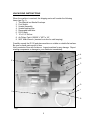
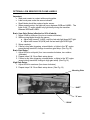
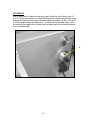
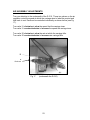
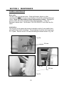
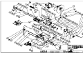
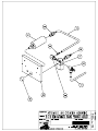
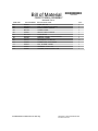
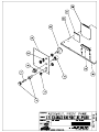
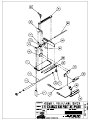
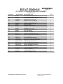
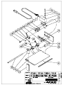
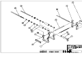
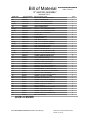
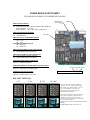
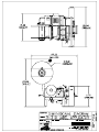
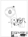
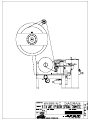
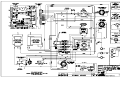
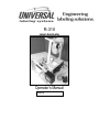
R-310
Label Applicator
Operator’s Manual
Serial #
Operator’s Manual
Version: H 8/5/2004
The information in this manual is subject to change without notice. No part of this
manual may be reproduced or transmitted in any form or by any means, for any
purpose other that the purchaser’s personal use, without prior written consent
from Universal Labeling System, Inc.
Universal Labeling Systems, Inc.
3501 8th Ave South, Saint Petersburg, FL 33711
Phone (727) 327-2123 Fax (727) 323-4403
Web Site:
http://www.universal1.com
2
Table of Contents
SECTION 1
OVERVIEW ...................................................................................4
INTRODUCTION...........................................................................4
UN-PACKING INSTRUCTIONS....................................................5
PRODUCT WARRANTY...............................................................6
SPECIFICATIONS ........................................................................7
SECTION 2 SETUP ..........................................................................................8
ASSEMBLING THE R-310 ...........................................................8
FUNCTION OF UNWIND ASSEMBLY .........................................9
WEBBING THE R-310 ................................................................10
WASTE REMOVAL ....................................................................11
CARRIAGE ADJUSTMENT AND PRODUCT PLACEMENT .....12
SECTION 3 OPERATION ...............................................................................18
SECTION 3 OPERATION ...............................................................................19
TRI-TRONICS OPTICAL LABEL SENSOR................................19
OPTIONAL LION SENSOR FOR CLEAR LABELS ...................20
OFF DELAY ................................................................................21
TIMER ADJUSTMENT................................................................22
AIR ASSEMBLY ADJUSTMENTS .............................................23
AIR REGULATOR ......................................................................24
SECTION 4 MAINTENANCE..........................................................................25
GENERAL MAINTENANCE .......................................................25
SECTION 5 RECOMMENDED SPARE PARTS .............................................26
SECTION 6 DRAWINGS AND BILL OF MATERIALS ...................................27
MAIN ASSEMBLY ......................................................................27
AIR CYLINDER MOUNTING ASSEMBLY .................................27
FRONT PANEL ASSEMBLY ......................................................27
REGULATOR ASSEMBLY.........................................................27
LABEL SENSOR/PEELER ASSEMBLY ....................................27
OPTIONAL STARWHEEL /PEELER ASSEMBLY .....................27
UPPER IDLER ROLL ASSEMBLY.............................................27
STANDARD CARRIAGE ASSEMBLY .......................................27
13” UNWIND ASSEMBLY ..........................................................27
POWER MODULE ......................................................................27
DIMENSIONAL DIAGRAM .........................................................27
WEBBING DIAGRAM (OPTICAL)..............................................27
WEBBING DIAGRAM (OPTIONAL STARWHEEL) ...................27
ELECTRICAL DIAGRAM ...........................................................27
TECHNICAL SUPPORT.....................................................................................28
3
SECTION 1
OVERVIEW
INTRODUCTION
Thank you for purchasing the R-310 semi-automatic round product label
applicator. The R-310 is known for high quality and operating convenience. With
proper maintenance it will provide many years of dependable and trouble free
service. We wish you much success with this product and will always welcome
any suggestions you may have as to how we may improve our products. Read
this manual and familiarize yourself with the machine before using this
equipment.
Operation:
A round product is placed on the carriage rollers and against the end stop. When
the operator presses the foot switch, a time delay cycle that controls an air
cylinder is activated, the drive roller starts to rotate, and the label starts it’s
dispense cycle. Air supplied to the cylinder causes the carriage holding the
product, to be elevated into contact with the drive roller. When the product
makes contact with the drive roller, it will start to turn. At this point, the label is
being peeled from the backing paper and will contact the product just in front of
the drive roll. As the product continues to turn, the drive roller will press the label
onto the container until the label is completely applied. The carriage will drop,
the product can be removed, and the machine is ready to repeat the cycle.
4
UN-PACKING INSTRUCTIONS
When the machine is received, the shipping carton will contain the following
items (see Fig 1).
1. This Manual in a Manila Envelope.
2. Foot Switch.
3. Unwind Assembly.
4. Unwind backing disc.
5. Removable label disc.
6. R-310 Body.
7. 10’ of 1/4” Air line.
8. Air Fitting, Part # 100220 ¼” NPT x 1/4”.
9. 9/64” Allen Wrench. (inserted in air line for safe keeping)
Carefully unpack the R-310 and place machine on a table or suitable flat surface.
Be sure no small parts are left in box.
Verify contents of box with list above. Inspect machine for any damage. Report
missing components or damage to your distributor immediately.
4
5
6
3
1
9
7
2
8
Fig 1
5
PRODUCT WARRANTY
Universal Labeling Systems, Inc. warranties all parts to be free from defects in
material and workmanship for a period of one year from the date of shipment
from our facility.
This guarantee is based upon equipment being used 8 hours per day, or 40
hours per week, or in any increment which does not total more than a single shift
operation, or 2,080 hours per year. Warranty will be reduced proportionally.
This warranty does not cover parts failure caused by lack of normal maintenance,
abuse or misuse of the equipment.
PERFORMANCE GUARANTEE
All equipment manufactured by Universal Labeling Systems, Inc. carries a 30day performance guarantee. If your machinery does not perform as described in
our quote to you within 30 days of shipping, Universal Labeling Systems, Inc. will
make every attempt to correct it. If after a reasonable period of time, the
machinery does not meet the specified performance, we will take your machine
back and reimburse you in full.
6
SPECIFICATIONS
Electrical Power:
Compressed Air:
Product size:
Web width:
Machine Size:
Weight:
Shipping Weight:
120VAC +/- 10%, 5 Amps, 60Hz
Clean, Dry, 20-40PSI, 5CFM
½” to 6” (12.7mm to 154.2mm)
7-1/8” (180.97mm) web capacity
on 3” (76.2mm) core – 12” (304.8mm) diameter roll
21.24” Wide 27.36” Deep 24.32” Tall
(539.5mm Wide X 695mm Deep X 617.7mm Tall)
52 lbs (19.4 Kg)
69 lbs (25.7 Kg)
7
SECTION 2
SETUP
ASSEMBLING THE R-310
The only item that needs to be added to the R-310 is the Unwind Assy.
1. Turn your attention to the back of the R-310 where the AC Electrical cord
is attached.
2. Remove the two screws where the Unwind Assembly will be assembled to
the body using a 3/16” Allen wrench (not provided).
3. Remove the plates from the Unwind to reduce weight and make it easier
to mount the assy.
4. Using a Square, mount the Unwind Assembly as shown below in Fig 2.
The Long screw (¼-20 x 1-1/2”) goes in the top hole. The shorter screw
(1/4-20 x 1-1/4”) is in the bottom.
Note: Double check squareness after the screws are tight and make
adjustments as necessary. The Unwind Assembly needs to be square to insure
proper tracking of the labels onto the product.
Label Sensor
Plug
Longer screw
¼-20 x 1-1/2”
Coder Plug for
Optional Hot
Stamp Coder
Foot Switch
Plug (on side)
AC cord
Fig 2
8
FUNCTION OF UNWIND ASSEMBLY
The unwind is simple, but important to the operation of the R-310 machine.
When the motor starts, the web and labels are pulled through the machine by the
drive roller. The label stock pulls on the brake arm, releasing the brake, and
allows the roll of labels to unwind. When the motor stops, the brake arm returns
to the rest position. This movement tightens the brake band around the 3"
diameter main unwind hub and the roll of labels stops unwinding.
The R-310 has a fixed speed, AC drive motor which transmits power to the drive
roller. The AC drive is directly influenced by the load it is trying to pull. In this
case, the load is the tension of the brake arm spring and the weight of the roll of
labels. The brake arm spring shown below in Fig 3, should be fastened to the
unwind assembly mounting bar in the tapped hole which provides the least
amount of tension at the brake arm. (The hole closest to the hub.)
If the R-310 is dispensing a long label (10" for example), you may have to
increase the tension on the brake arm spring (Move spring attachment point to
lower hole - See Fig 3) to keep the brake arm from bottoming out.
The length and speed figures mentioned above are only examples. Your
observation of the unwind operation will be the best indication of when a tension
change may be needed.
Dancer Arm
Spring located in top
hole. Move to bottom
hole for larger labels.
Fig 3
9
WEBBING THE R-310
Place the roll of labels on the unwind spool. Install the label disc and while
pressing it against the label reel, tighten thumbscrew. Remove enough labels so
only backing paper is threaded from peeler plate back to rewind spool. Pull the
web over the anti-stripper roller and down under the web guide shaft, between
the web guides. Set the web guides so that the web is held with minimum side
play but still moves freely. Pull the web around the peeler plate and the roller
attached to the peeler assembly underneath. Wind the web over the top roller
and between top and bottom roller and back under bottom roller to rewind spool.
Fig 4
10
WASTE REMOVAL
To remove waste web, turn off the machine, and remove the waste web retention
clip. Tear the web as shown in Fig 5. While holding the rewind backing plate, turn
the whole waste web in the opposite the direction and pull.
Fig 5
11
CARRIAGE ADJUSTMENT AND PRODUCT PLACEMENT
SET CARRIAGE AS FOLLOWS
1. The product centerline should be slightly behind drive roller centerline (a
1/32” or less) when carriage is up, as shown by ‘Y’ in Fig 6;
2. When product “A” is against drive roller, you should have a minimum 3/16”
distance (see ‘Z’ Fig 6) between product and peeler plate for product to sit
well down between carriage idler rollers (see ‘B’ Fig 6).
Use a 9/64 Allen wrench to loosen 4 cap screws “C” and relocate carriage
blocks. Also keeps in mind that moving the lower carriage roller assembly
forward or back in the actuator arm will affect values of ‘Y’ and ‘Z’. Refer to Fig 7
on page 13 for this adjustment. You will have achieved close to equal spacing if
roller centers visually form a triangle as shown by dotted lines in Fig 6.
After verifying that a product works well at a given setting, it would be a good
idea to mark the rods where carriage blocks are set.
Drive
Roller
X
Z
Product “A”
B
Drive Roller Centerline
Y
Product Centerline
Fig 6
Carriage Blocks
“C” Cap Screws
12
HORIZONTAL CARRIAGE ADJUSTMENT
Using adjusting screws (see ‘D’ Fig 7), you may slide “Standard Carriage
Assembly” left or right to improve or change alignment of product with label.
When making this adjustment, you should check position of product drive roller
(see Fig 6 previous page) to be sure it is still located to properly roll down label.
To adjust drive roller, loosen the set screws (see ‘E’ Fig 7) in the roller and move
left or right as required.
E
D
Fig 7
13
VERTICAL CARRIAGE ADJUSTMENT
This adjustment provides a means to relocate the lower carriage roller assembly
into one of several pair of holes in the actuator arm, as shown by dotted lines in
Fig 8. The purpose is, to minimize the distance the product has to travel to
contact the drive roller (see ‘X’ Fig 6) page 12). To adjust the assembly loosen
the two 8-32 screws (see ‘E’ Fig 8 & Fig 9) on side of actuator arms and relocate
roller assembly. Use 8-32 screws ‘F’ to adjust bottle stop ‘G’ to best position the
label onto the product. The view of the carriage is set to run a Fasson chart #4
(left side off first) die cut label.
F
G
E
Use one
of several
pairs of
holes
Fig 8
Standard
Carriage
Assy.
G
E
F
Fig 9
14
CARRIAGE ADJUSTMENT FOR TAPERED PRODUCTS
A tapered product can be labeled on the R-310 by adjusting the carriage as
follows.
1. Remove the tie bars on the bottom of the carriage assembly (see ‘H’ Fig. 10).
There are 8 screws as shown in (see ‘J’ Fig 10).
H
J
Fig 10
2. Loosen the screws on the carriage blocks (see ‘K’ Fig 10a.)
3. Separate or move closer the rollers on one or both sides of the carriage
depending on the taper of the product.
K
Fig 10a
15
4. Place a product on the rollers and move the product and roller assembly so
the product contacts the drive roll evenly.
5. Position the whole carriage at an angle (see Fig 10b). This is so the label
starts onto the product at an angle. This may seem contradictory, but the label
must start at an angle so it ends up looking straight on the product.
Note: Tapered
Product must
contact Drive
roll parallel for
straight label
transfer.
Fig 10b
The Drive roller may need to be moved to allow the product contact the roller
parallel by loosening the 4 set screws (see ‘L’ Fig 10c). Also the bottle stop was
positioned so the product rests against it for consistent label placement.
L
Fig 10c
Snug all screws and label a product or two and examine it for wrinkles or
position. Tighten all screws when adjustments are finished.
16
PEELER PLATE ADJUSTMENT
The peeler plate assembly may require adjustment with the change of label
length or product diameter. A short label with a small diameter product would
require the edge (see ‘A’ Fig 11) of the peeler plate to be closer to the Product
Drive Roller ‘B’ than a long label with a larger diameter product and will have to
be adjusted accordingly.
B
Fig 11
A
Move Closer
17
ADJUST PEELER PLATE AS FOLLOWS
1. Using the provided 9/64” Allen wrench just loosen – DO NOT REMOVE the two 8-32 SHCS located on the left side of the peeler assy. (see “C” in
Fig 12)
2. Using a 5/32” Allen wrench just loosen – DO NOT REMOVE - the two 1032 SHCS located to the right of the peeler assembly (see “D” in Fig 12).
3. Adjust the peeler plate.
4. Re-tighten all screws.
D
Fig 12
C
18
SECTION 3
OPERATION
TRI-TRONICS OPTICAL LABEL SENSOR
Normal Label Opacity Autoset Button:
This category includes most paper or metallized film labels adhering to paper or
transparent backing materials.
To implement the one button Autoset routine, utilize the external alignment
guides to position the gap between labels in line with the dot shown in the center
of the detection zone (see ‘A’ Fig 13). Then push the Autoset button marked
“Normal”.
Translucent Label Opacity Autoset Button:
This category includes translucent labels adhering to transparent backing
materials.
First utilize the external alignment guides to position the gap between labels in
line with the dot shown in the center of the detection zone. Then push the
Autoset button marked “Translucent”. The next step is to move the web so that
the translucent label goes in and out of the light beam. The red led output
indicator should go on when the label passes through the detection zone.
Note: The status of the red led and output transistors can be inverted by
pressing both buttons simultaneously. When the output status had been
inverted, the red led and the output transistors will turn off when the label comes
into view.
A
Fig13
19
OPTIONAL LION SENSOR FOR CLEAR LABELS
Important:
• Web must remain in contact with mounting plate.
• Label must pass under the sensor indicator
• Small labels should be centered under sensor.
• When properly setup, the lights will move between WEB and LABEL. The
lights in the “X” region should only light briefly during the transition
between WEB and LABEL.
Basic (Low Gain) Setup (effective for 90% of labels):
1. Adjust SPAN to minimum (four turns counter-clockwise)
2. While moving labels through the sensor.
a. Adjust shift toward L (LABEL) until the last web light does NOT light.
b. Adjust shift toward W (WEB) until the last web light DOES light.
3. Setup complete.
4. If there is any false triggering, missed labels, or lights in the “X” region
except during transition, change to medium gain setup. (See Fig 14)
Basic Gain Setup:
1. Adjust SPAN to mid-point (four turns counter-clockwise, two rotation
clockwise)
2. Repeat steps 2 & 3 from Basic setup above.
3. If there is any false triggering, missed labels, or lights in the “X” region
except during transition, change to high gain setup. (See Fig 14)
High Gain Setup:
1. Adjust SPAN to maximum (four turns clockwise)
2. Repeat steps 2 & 3 from Basic setup above. (See Fig 14)
Mounting Plate
“SHIFT”
Fig 14
“X” area
“SPAN”
20
OFF DELAY
The off delay dial is located on the front panel, below the on/off switch (see ‘A’
Fig 15). When the machine is cycled, the label sensor sends a signal when a gap
between the labels on the web is detected telling the machine to stop. Off delay
is used to adjust where the label stops. To adjust where the label stops, cycle
the machine and adjust the off delay until the label stops at the desired distance
from the peeler edge.
A
Fig 15
21
TIMER ADJUSTMENT
Select the product to be labeled and place it on the white carriage rollers. Move
the product to the right against the bottle stop, take your hands away from
carriage area then depress the foot switch. After the carriage drops back down,
remove the product and inspect the label for proper application. If label
placement is correct, continue this procedure and occasionally check label.
Minor adjustments to the machine may increase productivity. For example, the
control knob on top near the back of the dispenser adjusts the time the product is
in contact with the drive roller. This allows the product to drop as soon as label is
applied. Doing so will allow an experience user to label more products during a
period of time. Once the machine is set up properly, the operator’s dexterity is
the key to speed. If you make machine adjustments and are not sure of their
effect, do only one adjustment at a time in small increments.
Timer:
The timer adjustment dial on top of the applier (“J”, Fig 16), allows you to adjust
the time that the carriage is held up to apply a label. For long labels the carriage
assembly. needs to stay up longer to insure the label wraps all the way around
the product. Turn dial clockwise to increase time the carriage stays up. Turn
counterclockwise to decrease the time.
Note: The smaller knobs on the timer are not used at all.
J
Fig 16
22
AIR ASSEMBLY ADJUSTMENTS
Turn you attention to the underneath of the R-310. These two valves on the air
regulator control the speed at which the carriage rises to label the product and
falls back to rest. Each can be controlled individually as shown below (see Fig
17).
Turn valve ‘A’ clockwise to slow the speed that the carriage rises.
Turn valve ‘A’ counterclockwise to increase the speed the carriage rises.
Turn valve ‘B’ clockwise to slow the rate at which the carriage falls.
Turn valve ‘B’ counterclockwise to increase rate carriage falls.
B
A
Red hose
Fig 17
(underneath the R-310)
23
AIR REGULATOR
Turn your attention to the side where the air regulator is mounted (see Fig 18).
The Air Regulator is used to raise or lower the air pressure to the machine. This
will allow the R-310 to run connected to virtually any clean air source depending
on how much Air pressure is produced by your compressor. It is also used to
stay within the recommend air pressure of the machine 20-40PSI, 5CFM.
Note: The R-310 is designed to label a variety of items from very small up to and
including a Full Gallon jug. The Air regulator would also be used to increase air
pressure to raise a heavy Full gallon jug. By the same token if a small vial were
being labeled, not nearly as much air pressure would be needed to lift an item
that weighed a few ounces or less. You want the carriage to rise smoothly and
stay engage with the driver roller to insure proper labeling. Then again you don’t
want it to rise so fast that it bang’s against the driver roller and cause damage to
your product or the machine.
The Air pressure takes a few seconds to increase so don’t turn the knob ‘F’ too
much. Also a small amount of turn may increase the pressure a lot.
Turn the regulator knob ‘F’ slowly a ¼ turn and pause a few seconds watching
the gauge as it rises. Try to label the product and then repeat as necessary.
Turning the regulator a small amount then pause.
Adjust knob ‘F’ clockwise to increase air pressure, counterclockwise to decrease
it, watching the Air pressure gauge ‘E’.
F
E
Fig 18
24
SECTION 4
MAINTENANCE
GENERAL MAINTENANCE
Drive rolls:
The drive rolls must be kept clean. Wash with lacquer thinner or other
recommended solvents to remove gum buildup or small bits of labels adhering to
rollers. Never use razor blade or sharp instruments on rollers. Damaged or
gummy rollers will cause inconsistencies in label application. If they are
damaged, replace them. Part Number “SRL-500-3403875” both rollers are the
same.
Lubrication:
The only part in the applier that requires lubrication are the 2 main shafts (drive
and rewind) that rotate in bushings. These bushings should be oiled once every
2 or 3 years. Remove cover to oil internal bushings as shown below in Fig 19b.
Fig 19a
Oil here
Fig 19b
Oil here
Fig 19c
25
SECTION 5
RECOMMENDED SPARE PARTS
Part Number
Description
100099
100303
200009
200044
200045
200109
200111
200113
200198
300050-2
300051-2
300055-1
300060-1
420210
600300
820000
200090B
200374-1
200376B
210131B
420200-01.60
L-128-C-A
L-129-S
SRL-500-3303875
SRL-500-3306000
SRL-500-3403875
VALVE, 120VAC 3WY MAC AIR
CYLINDER, 1" SPRING RETURN AIR
RELAY, 12VDC 10AMP DPDT
FUSE, AGC 5 A
FUSE, AGC 7 A (USED W/ CODER)
SWITCH, MICRO (STARWHEEL)
(IF EQUIPPED)
TRANSFORMER, 110VAC TO 15VAC
TIMER, (CROUZET)
MODULE, POWER
MOTOR, CW W/BRAKE
MOTOR, CCW WO/BRAKE (PRODUCT DRIVE)
FAN, #300050 MOTOR
FAN, #300051 MOTOR
UNWIND SPRING, ½” X 4” EXTENSION
UHMW, TAPE, 1" X 50' ROLL
THUMBSCREW, 1" BLACK NYLON
ASSEMBLY, R-310 FOOT SWITCH
SENSOR, LABEL EYE(TRI-TRONICS)
ASSY. CABLE W/4 PIN M. AMPHENOL
ASS'Y, CLEAR/FOIL LABEL SENSOR (IF EQUIPPED)
SPRING, EXTENSION
CLIP, (6-1/2 WEB) RETENTION
STARWHEEL, LABEL SENSING
(IF EQUIPPED)
ROLLER, 3-7/8" PRODUCT DRIVE
ROLLER, PROD. DRIVE 6" LONG
ROLLER, 3-7/8" UPPER IDLER
26
SECTION 6
DRAWINGS AND BILL OF MATERIALS
MAIN ASSEMBLY
See Drawing 310-I-00H
AIR CYLINDER MOUNTING ASSEMBLY
See Drawing 310-I-10
FRONT PANEL ASSEMBLY
See Drawing 310-I-20F
REGULATOR ASSEMBLY
See Drawing 310-I-30
LABEL SENSOR/PEELER ASSEMBLY
See Drawing 310-I-40F
OPTIONAL STARWHEEL /PEELER ASSEMBLY
See Drawing 310-I-41F
UPPER IDLER ROLL ASSEMBLY
See Drawing 310-I-50E
STANDARD CARRIAGE ASSEMBLY
See Drawing 310-I-62
13” UNWIND ASSEMBLY
See Drawing UWA-13R-I-00
POWER MODULE
See Drawing L15-D-02
DIMENSIONAL DIAGRAM
See Drawing 310-F-00F
WEBBING DIAGRAM (OPTICAL)
See Drawing 310-W-00F
WEBBING DIAGRAM (OPTIONAL STARWHEEL)
See Drawing 310-W-00F
ELECTRICAL DIAGRAM
See Drawing 310-E-00H
27
TECHNICAL SUPPORT
When calling for Technical Support:
Have your Model #: R-310H
And the Serial Number ready (located on main base plate on the same side
where the Air Regulator is).
Email:
[email protected]
Web Site:
http://www.universal1.com
28
Bill of Material
*310-I-00H*
310-I-00H
MAIN ASSEMBLY
MACHINE: R310
ITEM NUM:
01
02
03
04**
05
06
07*
08
09
10
11
12
13
14*
15*
16
17
18
19
20
21
22
23
24
25
26
27
28
29*
30
31
32*
32***
33
34
35
36
37
38
39
40
41
42
43
44
45
PART NUMBER: PART DESCRIPTION:
SRL-500-42
BRACKET, OUTER BEARING
L-144-M
BLOCK, 3/8" BEARING
400016
BEARING, 3/8" SEALED
SRL-500-3306000 ROLLER, PROD. DRIVE 6" LONG
SRL-500-04-B
SHAFT, 3/8 X 15.5"
SRL-500-03
SHAFT, PIVOT
310-I-62
ASSEMBLY, STANDARD CARRIAGE
SRL-500-43
BRACKET, MACHINE SUPPORT
SRL-500-40
PLATE, BASE
SRL-500-23
BAR, LOWER TIE
SC-006
COLLAR, SET .376 X .62 X .250
430380
BUSHING,S 500 X 375 X 375
SRL-500-41
BRACKET, MOTOR MOUNT
310-I-30
ASSEMBLY, AIR REGULATOR
310-I-10
ASSEMBLY, AIR CYLINDER MNTG.
SRL-500-60
BAR,OUTSIDE TIE
SRL-500-61
BAR, INSIDE TIE
SRL-500-08
COLLAR, PRODUCT DRIVE SHAFT
300051-2
MOTOR, CCW WO/BRAKE
300060-1
FAN, #300051-2 MOTOR
SRL-500-29
COVER, MOTOR
MD-724-1
SUPPORT, REAR COVER
MD-723
SUPPORT, TOP COVER
MD-724
SUPPORT, FRONT COVER
200021
STRIP, 8 TERMINAL EURO 40.208
200111
TRANSFORMER, 110VAC TO 15VAC
MD-700-1
PLATE, BASE
SRL-500-44
SUPPORT,TOP
310-I-20F
ASSEMBLY, FRONT PANEL
810075
PIN, 1/4 X 1 DOWEL
MD-731
STAND-OFF, MOTOR
310-I-40F
ASSEMBLY, PEELER/LABEL SENSOR
310-I-41F
ASSEMBLY, OPTIONAL STARWHEEL/PEELER
MD-730-1W
SHAFT, BOTTOM DRIVE ROLL
SRL-500-3403875 ROLLER, 3-7/8" UPPER IDLER
420200-01.60
SPRING, EXTENSION
430385
BUSHING,S 500 X 375 X 500
MD-744-W
PLATE, EXTENSION
JL-200-37-5A
ASSEMBLY. REWIND SLIP CLUTCH
MD-728-1
ASSEMBLY, DRIVE SPROCKET
410000-13.25
ASSEMBLY. CHAIN,#25 LINK X 13-1/4"
MD-746-1
SPROCKET, TENSION
JL-200-42
SPROCKET, REWIND CLUTCH
300050-2
MOTOR, CW W/BRAKE
300055-1
FAN, #300050-2 MOTOR
SRL-500-59-1
LEG, STAND-OFF 4"
F:\LABELERS\R-310\Manual\310-I-00H.dwg
QTY:
1
1
1
1
1
1
1
1
1
2
4
4
1
1
1
1
1
1
1
1
1
1
1
1
1
1
1
1
1
1
3
1
1
1
1
2
1
1
1
1
1
1
1
1
1
2
MSACCESS Y:\databases\BOM2000.MDE
9/8/2005 4:15:26 PM
Bill of Material
*310-I-00H*
310-I-00H
MAIN ASSEMBLY
MACHINE: R310
ITEM NUM:
46
47
48
49
50
51
52
53*
54
55
56
57
58
59
60
61
62
63
64
65
66
67
68
69
70
71
72
73*
74
75
76
77
78
79
80
81
82
83
84
85
PART NUMBER: PART DESCRIPTION:
SRL-500-58
FOOT, EQUIPMENT (PACK OF 2)>>
MD-746-3
BLOCK, PIVOT
MD-700-2
PLATE, VERTICAL
430240
BUSHING, 500 X 375 X 375
MD-743-W
SHAFT, UPPER IDLER
700025
GUIDE, 1/2" SPLIT NYLON WEB>>
PS-3018
PIN, 1/4"OD X 5/8" DOWEL
310-I-50E
ASSEMBLY, UPPER IDLER ROLL
L-172-09
WASHER, UHMW 032 X 257 X 500
MD-708-W
BAR, OUTBOARD SUPPORT
L-128-C-A
CLIP, (6-1/2 WEB) RETENTION
L-128-D-A
SPOOL, (6-1/2 WEB) REWIND
L-148-M
PLATE, REWIND BACKING
SRL-500-71
SHAFT, REWIND
200011
SOCKET, 10 AMP RELAY
200009
RELAY, 12VDC 10AMP DPDT
MD-722
BRACKET, RELAY
L-172-03
WASHER, UHMW 062 X 380 X 625
MD-732
BRACKET, UNWIND MOUNTING
MD-764
COVER, REAR
MD-726-1
SUPPORT, REWIND SPINDLE
400054
WASHER, 3/8" WAVE SPRING
400010
RETAINER, 3/8" HARDENED BRNG.
400009
BEARING, 3/8" THRUST
MD-719-1A
COVER, TOP
MD-733
SPACER, MOUNTING BAR
MD-734
BAR, HORIZONTAL MOUNTING
UWA-13R-I-00
ASSEMBLY, R. H. 13" UNWIND
200015
AMPHENOL, 4 PIN FEMALE
200017
AMPHENOL, 5 PIN (FEMALE)
200036
CORD, 18/3 8FT. SJT POWER
200034
RELIEF, 1/16" STRAIN
200113
TIMER, (CROUZET)
200114
SOCKET, SYRELEC TIMER MNTG.
MD-747
BLOCK, SYRELAC TIMER SUPPORT
MD-725
SUPPORT, COVER
MD-718-1
COVER, VENTED SIDE
200013
AMPHENOL, 3 PIN (FEMALE)
200090B
ASSEMBLY, R-310 FOOT SWITCH
L-172-21
WASHER, NYLON .125 X .194 X .375
F:\LABELERS\R-310\Manual\310-I-00H.dwg
QTY:
2
1
1
1
1
2
2
1
2
1
1
1
1
1
1
1
1
2
1
1
1
2
2
1
1
4
2
1
1
1
1
1
1
1
1
1
2
1
1
4
MSACCESS Y:\databases\BOM2000.MDE
9/8/2005 4:15:26 PM
Bill of Material
*310-I-00H*
310-I-00H
MAIN ASSEMBLY
MACHINE: R310
ITEM NUM:
PART NUMBER: PART DESCRIPTION:
QTY:
* SEE DRAWING
** SRL-500-3306000 IS A STANDARD 6" ROLLER
FOR CUSTOM LENGTH CHANGE LAST 5 DIGITS
I.E. 4-3/8 = 04375
*** OPTIONAL
F:\LABELERS\R-310\Manual\310-I-00H.dwg
MSACCESS Y:\databases\BOM2000.MDE
9/8/2005 4:15:26 PM
Bill of Material
AIR CYLINDER MOUNTING ASSEMBLY
ITEM NUM:
01
02
03
04
05
06
07
08
09
10
11
R310
PART NUMBER: PART DESCRIPTION:
100099
100108
100109
100211
100224
100226
100303
SRL-500-12A
SRL-500-19
100430-9.125
100425-7.00
VALVE, 120VAC 3WY MAC AIR
FTNG, MINI NEEDLE VALVE
VALVE, 1/4 x 1/8 METER-IN
FTNG, 1/8 TO 1/4 STRT CONN.
FTNG, 10-32M TO 1/4 BARB
FTNG, 1/8M TO 10-32F REDUCER
CYLINDER, 1" SPRING RETURN AIR
GUARD, AIR CYLINDER
PLATE, AIR CYLINDER M0UNTING
AIRLINE, 1/4" X 9-1/8" BLUE
AIRLINE, 1/4" X 7" RED
F:\LABELERS\R-310\310-I-10.dwg
QTY:
1
1
1
1
1
1
1
1
1
1
1
MSACCESS X:\SALES\BOM
Bill
of Material
FRONT PANEL ASSEMBLY
*310-I-20F*
310-I-20F
MACHINE: R310
ITEM NUM:
01
02
03
04
05
06
07
08
09
10
11
12
13
PART NUMBER: PART DESCRIPTION:
200044
FUSE, AGC 5 A
200192-1
DIAL, 10 TURN POT (H-22-6A)
200059
PLATE, ON/OFF SWITCH
MD-763
COVER, FRONT
200030
SWITCH, DPST TOGGLE
MD-700-1
PLATE, BASE
600345A
RUBBER, CIRCUIT CARD BACKING
200198
MODULE, POWER
200175
SPACER, #6 X .75 NYLON
200022
CONNECTOR, 15 PIN EDGE
200216
POT, 5K OHM 3-TURN
200001
GROMMET, 1/16" X 1/4"
200005
HOLDER, PANEL MOUNT FUSE
F:\LABELERS\R-310\Manual\310-I-20F.dwg
QTY:
1
1
1
1
1
1
1
1
2
1
1
1
1
MSACCESS Y:\databases\BOM2000.MDE
8/21/2003 8:06:06 AM
Bill of Material
REGULATOR ASSEMBLY
ITEM NUM:
01
02
03
04
05
06
07
08
09
10
R310
PART NUMBER: PART DESCRIPTION:
100300
100229
100217
100321
100301
100210
100203
100228
100405-120
100220
REGULATOR, AIR
OBSOLETE USE 100209
OBSOLETE-USE# 100345
NUT, PANEL MOUNT AIR REGULATOR
GAUGE, 1.5 DIAMETER AIR
FTNG, 1/8 COUPLING
FTNG, 1/8M ELBOW
FTNG, 1/8 SOCKET PLUG
AIRLINE, 1/4" X 10' WHITE
FTNG, 1/4M TO 1/4F
F:\LABELERS\R-310\310-I-30.dwg
QTY:
1
1
2
1
1
1
1
1
1
1
MSACCESS X:\SALES\BOM
Bill of Material
LABEL SENSOR/PEELER ASSEMBLY
*310-I-40F*
310-I-40F
MACHINE: R310
ITEM NUM:
01
02
03
04
05
06
07
08
09*
10*
11
12
13
14
15
16
17
18
19
20
21
22
23
PART NUMBER: PART DESCRIPTION:
MD-756
BAR, OPTICAL LABEL SENSOR ADJ.
SRL-500-57-1WA SHAFT, WEB DRAG
MD-755
BLOCK, PEEL PLATE ADJUSTING
MP-2500-9
PLATE, WEB DRAG PRESSURE
MD-762
PLATE, PEELER
600300-07.500
UHMW, TAPE, 1" x 7-1/2" L.
MD-758
BLOCK, SENSOR MOUNTING
200374-1
SENSOR, LABEL EYE(TRI-TRONICS)
MD-765
BRACKET, SENSOR MOUNTING
210131B
ASSEMBLY. CLEAR/FOIL LABEL SENSOR
MD-754
BLOCK, 3/8" SHAFT
L-172-08
WASHER, UHMW 187 X 375 X 625
200376B
ASSEMBLY. CABLE W/ 4 PIN AMPHENOL
MD-706-W
BAR, STRIPPER PLATE SUPPORT
500525-7.170
ROLLER, IDLER
MD-759
SHAFT, DEFLECTION ROLLER
MD-761
PLATE, PEELER ASSEMBLY
MD-757
BLOCK, SENSOR ADJUST
MD-766
BLOCK, WEB DRAG MOUNTING
L60-0035
BLOCK, WEB DRAG
850008T
THUMBSCREW, 8-32 X 1/2"
MD-760
BLOCK, PEELER PLATE SUPPORT
500081
HANDLE, 10-32 MALE RATCHET
QTY:
1
1
1
2
1
1
1
1
1
1
2
2
1
1
1
1
1
1
1
2
2
1
1
* OPTIONAL CLEAR LABEL SENSOR
F:\LABELERS\R-310\Manual\310-I-40F.dwg
MSACCESS Y:\databases\BOM2000.MDE
4/9/2004 2:23:11 PM
Bill of Material
OPTIONAL STARWHEEL/PEELER ASSEMBLY
*310-I-41F*
310-I-41F
MACHINE: R310
ITEM NUM:
01
02
03
04
05
06
07
08
09
10
11
12
13
14
15
16
17
18
19
20
21
22
23
24
25
26
27
28
29
PART NUMBER: PART DESCRIPTION:
855001
SHOULDER BOLT, 1/4 X 1/2" L.
L-170
PIN, STARWHEEL PIVOT ARM ASSEMBLY.
L-129-S
STARWHEEL, LABEL SENSING
SRL-500-73
BUSHING, 313 X 250 X 495
420175B
SPRING, 3/16 X 1-1/8 EXT. SS
200600-A
BOLT, COUPLER MOUNTING
420175A
SPRING, 3/16 X 3/4 EXT. SS
200109
SWITCH, MICRO
L-164
SPACER, MICRO SWITCH
200016B
ASSEMBLY, OPTIONAL STARWHEEL SWITCH CABLE
200001
GROMMET, 1/16" X 1/4"
850015T
THUMBSCREW, 6-32 X 1-1/4"
854008
NUT, 6-32 HEX SS
853008
WASHER, #6 FW SS
MD-717
COVER, STARWHEEL (BLACK)
SRL-500-65
BRACKET, LABEL SENS. MOUNTING
854009
NUT, 10-24 HEX SS
SRL-500-81
PLATE, PEELER ADJUSTING
SRL-500-32
BRACKET, STARWHEEL SUPPORT
SRL-500-64A
BRACKET, STARWHEEL MOUNTING
600300-07.500
UHMW, TAPE, 1" x 7-1/2" L.
MD-706-W
BAR, STRIPPER PLATE SUPPORT
SRL-500-31-W
PLATE, WL/GALLON PEELER
SRL-500-57A
BLOCK, WEB DRAG MOUNTING
SRL-500-57-1WA SHAFT, WEB DRAG
MP-2500-9
PLATE, WEB DRAG PRESSURE
L60-0035
BLOCK, WEB DRAG
850008T
THUMBSCREW, 8-32 X 1/2"
SRL-500-66
ARM, STARWHEEL PIVOT
F:\LABELERS\R-310\Manual\310-I-41F.dwg
QTY:
1
1
1
1
1
1
1
1
1
1
1
1
1
1
1
1
1
1
1
1
1
1
1
1
1
2
2
2
1
MSACCESS Y:\databases\BOM2000.MDE
4/9/2004 2:40:35 PM
Bill
of Material
UPPER IDLER ROLL ASSEMBLY
*310-I-50E*
310-I-50E
MACHINE: R310
ITEM NUM:
01
02
03
04
05
06
07
08
09
10
11
12
PART NUMBER: PART DESCRIPTION:
430180
BUSHING, 375 X 313 X 375
SRL-500-74
BUSHING,S 375 X 313 X 280
MD-707-1-W
BAR, PIVOT TIE (WIDE LABEL)
MD-707-2
BLOCK, OUTER BEARING
MD-707-3
BLOCK, INNER BEARING
SRL-500-3403875 ROLLER, 3-7/8" UPPER IDLER
MD-730-2-W
SHAFT, IDLER WIDE LABEL
SC-005
COLLAR, SET .313 X .62 X .25
850005
SCREW, 6-32 X 1/2" L SHCS
430125
BUSHING, 313 X 250 X 250
857004
SET SCREW, 10-32 X 1/4" SS
857003
SET SCREW, 8-32 X 1/8" L SS
F:\LABELERS\R-310\Manual\310-I-50E.dwg
QTY:
2
2
1
1
1
1
1
2
4
2
2
2
MSACCESS Y:\databases\BOM2000.MDE
8/21/2003 8:40:08 AM
Bill of Material
STANDARD CARRIAGE ASSEMBLY
*310-I-62*
310-I-62
MACHINE: R310
ITEM NUM:
01
02
03
04
05
06
07
08
09
10
11
12
13
14
15
16
17
18
PART NUMBER: PART DESCRIPTION:
SRL-500-62A
ASS'Y, IDLER ROLLER
SC-006
COLLAR, SET .376 X .62 X .250
SRL-500-05-1
SHAFT, LOWER BACK IDLER
SRL-500-14-D
COUPLER, IDLER SHAFT
SRL-500-14-E
CARRIER, LOWER IDLER ROLL
SRL-500-06-1
SHAFT, LOWER FRONT IDLER
L-143-D-03.000
ROLLER, 3" LOWER IDLER
SRL-500-02
SHAFT, CARRIER SIDE
SRL-500-03
SHAFT, PIVOT
SRL-500-09
BRACKET, LOWER CARRIAGE
SRL-500-15-1
PLATE, LOWER IDLER ROLL
SRL-500-11
BOTTLE STOP, PLASTIC
SRL-500-52
SHAFT, BOTTLE STOP
SRL-500-10
BRACKET, BOTTLE STOP
200600-A
BOLT, COUPLER MOUNTING
SRL-500-45
ARM, ACTUATOR
SRL-500-46
BAR, ACTUATOR ARM TIE
L-172-08
WASHER, UHMW 187 X 375 X 625
F:\LABELERS\R-310\Manual\310-I-62.dwg
QTY:
2
4
1
4
4
1
2
2
1
1
2
1
1
1
4
2
1
4
MSACCESS Y:\databases\BOM2000.MDE
8/21/2003 8:48:44 AM
Bill of Material
*UWA-13R-I-00*
UWA-13R-I-00
13" UNWIND ASSEMBLY
MACHINE: R310
ITEM NUM:
01
02
02 (A)
02( B)
03
04
04 (A)
04 (B)
05
06
07
08
09
09 (A)
09 (B)
10
11
12
12 (A)
12 (B)
13
14
15
16
17
18
19
20
21
22
23
24
25
26
27
28
29
30
31
32
33
34
35
PART NUMBER: PART DESCRIPTION:
UND-001
BAR, LABEL REEL MOUNTING
UND-002
SHAFT, UNWIND HUB
UND-002C
SHAFT, 7-1/2" WEB UNWIND
UND-002D
SHAFT, 8-1/2" WEB UNWIND
UND-003
ARM, UNWIND BRAKE
UND-004
SHAFT, BRAKE ARM
UND-004-07.50
SHAFT, 7-1/2" WEB BRAKE ARM
UND-004E
SHAFT, 8-1/2" WEB BRAKE ARM
UND-006
BLOCK, BELT FASTENER
UND-007
CLAMP, BELT
UND-008
STUD, BRAKE ARM
UND-009-1
STRAP, BRAKE
UND-011C
HUB, MAIN UNWIND
UND-011B
HUB, 7-1/2" WEB MAIN UNWIND
UND-011H
HUB, 8-1/2" WEB MAIN UNWIND
UND-013
DISC, REMOVABLE LABEL
UND-015
DISC, UNWIND BACKING
UND-038
ROLLER, BRAKE IDLER
UND-038-07.50
ROLL, 7-1/2" WEB BRAKE IDLER
UND-038E
ROLL, 8-1/2" WEB BRAKE IDLER
UND-037
BEARING, BRAKE ARM ROLLER
UND-019
CLAMP, INNER BACKING DISC
200409
CLIP, CORE (FOR HUB)
UND-042
CLAMP, OUTER BACKING DISC
UND-027
BEARING, END CAP ROLLER
430306
BUSHING, 750 X 500 X 625"
420210
SPRING, 1/2 X 3.125" EXTENSION
UND-046
BEARING, END CAP ROLLER
820000
THUMBSCREW, 1" BLACK NYLON
400059
BEARING, 5/8" THRUST W/WASHERS
856005
RING, 1/2" EXT. RETAINING
853003
WASHER, 1/4" .050 THK 5/8 ODFW
851002
SCREW, 1/4-20 X 1/2" HHMS
853001
WASHER, 5/16" FW SS
851003
SCREW, 5/16-18 X 1/2" HHMS SS
852001
SCREW, 10-32 X 1/2" FHMS PHIL
850002
SCREW, 10-32 X 1" L SHCS
854001
NUT, 10-32 HEX
850003
SCREW, 5/16-18 X 1-1/4" L SHCS
850006
SCREW, 6-32 X 5/8" L SHCS
850004
SCREW, 5/16-18 X 1" L SHCS
852501
SCREW, 4-40 X 1/4" L PHMS PHIL
854007
NUT, 4-40 HEX SS
QTY:
1
1
1
1
1
1
1
1
1
2
1
1
1
1
1
1
1
1
1
1
2
1
4
1
1
1
1
1
1
1
1
1
1
1
1
6
3
2
1
2
1
4
4
(A)=FOR 7-1/2" WIDE WEB
(B)=FOR 8-1/2" WIDE WEB
F:\ACCESSORIES\UND\MANUAL\UWA-13R-I-00.dwg
MSACCESS Y:\databases\BOM2000.MDE
9/9/2005 7:40:15 AM
POWER MODULE SETUP SHEET
PLEASE READ CAREFULLY BEFORE INSTALLING
SWITCH #1 DELAY SELECT
OFF - NO DELAY
ON - START AND STOP DELAY SET BY FRONT PANEL CONTROLS
START CONTROL - 0 TO 1 SEC.
STOP CONTROL - 0 TO 0.1 OR 1.0 SEC. (SEE JUMP 9)
SWITCH #2 MACHINE MODE SELECT
OFF - L15 OPERATION
ON - L60 OPERATION
CODER DWELL
ADJUSTMENT
R17
JUMPERS
J3
J1
SWITCHES
SWITCH #3 CLUTCH / BRAKE DELAY SELECT
[L15] SWITCH #3, W/SWITCH #2 OFF
OFF - 0 mS
ON - 25 mS
[L60] SWITCH #3, W/SWITCH #2 ON
OFF - BLOW-ON
ON - TAMP-ON
SWITCH #4 START SWITCH LOGIC LEVEL SELECT
OFF - FALLING SIGNAL EDGE ACTIVATION
ON - RISING SIGNAL EDGE ACTIVATION
SWITCH #5 STOP SWITCH LOGIC LEVEL SELECT
OFF - FALLING SIGNAL EDGE ACTIVATION
ON - RISING SIGNAL EDGE ACTIVATION
JUMPERS #6 START SWITCH TYPE SELECT
PINS 1 & 2 - SPDT START SWITCH
PINS 2 & 3 - SINGLE POLE INPUT
JUMPERS #8 SINGLE POLE START SWITCH POLARITY SELECT
PINS 1 & 2 - SWITCHES TO POSITIVE +5V TO +24V DC (PNP)
PINS 2 & 3 - SWITCHES TO GROUND (NPN)
MONTH / NUMBER / YEAR
JUMPERS #9 STOP DELAY SELECT
PINS 1 & 2 - LONG DELAY 0 TO 1 SEC.
PINS 2 & 3 - SHORT DELAY 0 TO 0.1 SEC.
PRINTED CIRCUIT BOARD # OO OOO OO
DEFAULT SETTINGS
L-15
L-60
R-310
SL-1000
The Universal Power Module is designed to
operate the L15, L20, L30, R310, MP25, L60,
and SL1000 series of label machines. The L15,
L20, L30 and MP25 are set up the same!
The L60, R310 & SL-1000 are different,
SEE DEFAULT SETTINGS.
Coder output is adjusted by (R17) top left board
and operates in all modes. The dwell time is
adjustable from 0 to 0.5 seconds. The next
start signal or product signal will be ignored until
the coder pulse is turned off.
(NOTE) IF YOU HAVE L-60 WITH FRONT & REAR
BOARD,
THE BOARD MUST BE SET UP AS L-15.