1
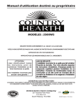
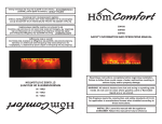
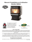
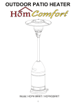
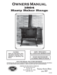
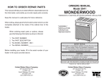
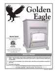
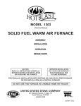
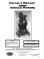
Owners Manual
1869
Caboose Potbelly
CAUTION!
Read All Instructions Carefully Before Starting The Installation or Operating This
Stove.
NOTE: THIS IS NOT A
U.L. LISTED COAL BURNING STOVE
DO NOT USE THIS HEATER
IN A MOBILE HOME OR TRAILER
SAVE THIS MANUAL FOR FUTURE REFERENCE
STATES STO
TED
V
NI
USSC
COMPANY
E
U
THIS MANUAL WILL HELP YOU TO OBTAIN EFFICIENT, DEPENDABLE SERVICE FROM THE HEATER, AND ENABLE
YOU TO ORDER REPAIR PARTS CORRECTLY. KEEP IN A SAFE PLACE FOR FUTURE REFERENCE.
UNITED STATES STOVE COMPANY
227 Industrial Park Road
P.O. Box 151
South Pittsburg, TN 37380
(423) 837-2100
Keeping America Warm
since 1869
851499
Illustrations
15"
STOVE DIMENSIONS
FIGURE 1.
36"
FLOOR
PROTECTOR
19.5"
21.6"
(FRONT VIEW)
(SIDE VIEW)
Specifications
Height (Overall)......................................
Width......................................................
Depth......................................................
Firebox Capacity....................................
Firebox Depth.........................................
Flue Size.................................................
Door Opening.........................................
36"
21.6"
19.5"
40 lbs.
10"
6"
8" x 10"
Material............................................
100% Cast Iron
Fuel....................................................................
Coal
NOTE: Bituminous, large nut to small egg or
Anthracite, large egg to small broken.
BTU Rating..................................................
Weight.........................................................
This stove has an oval flue
outlet and uses standard 6"
stovepipe.
Ill. 1
To attach pipe, simply hand
form the smooth end of the
round stove pipe into an oval
shape.
Ill. 2
Slide the crimped end of the
stove pipe into the oval flue
outlet and secure with metal
screw. Connect balance of
stove pipe into a class A
chimney
Ill. 3
2
200,000
216 lbs.
CONGRATULATIONS!
You have purchased a heater from North America's oldest manufacturer of wood and coal burning products. Our
Caboose Potbelly Stove is reminiscent of the potbelly stoves seen in the train stations and cabooses of yester year.
This high performance potbelly stove is constructed of all cast iron and is designed to burn coal. Its generous
firepot capacity with shaker grate allows 40 lbs. of coal to burn for eight hours before requiring refueling. Separate
ash door with slide draft control at bottom creates a "forge effect" that insures proper combustion. Long flared
top with 8" lift out lid facilitates fry pan or tea kettle. Stove comes assembled except for legs.
Safety Rules
SAFETY NOTICE: If this heater is not properly installed a house fire may result. For your safety, follow the
installation directions. Contact local building or fire officials about restrictions and installation inspection
requirements in your area.
Read these rules and the instructions carefully.
1.
The installation of this stove must comply with your local building code rulings. Please observe the clearances to
combustibles. (Refer to Figures 2 and 3) Stove must be 36" from a combustible wall (wood or plaster board) at
rear or sides.
2.
DO NOT install this stove in a mobile home or trailer.
3.
Always connect the stove to a chimney and vent to the outside. Never vent to another room or inside a building.
4.
DO NOT connect a wood burning to an aluminum Type B gas vent. This is not safe and prohibited by the NFPA
(National Fire Protection Agency) This stove requires approved masonry or a UL 103 HT Listed Residential Type
and Building Heating Appliance Chimney. Use a 6" diameter chimney or larger, that is high enough to give a good
draft.
5.
Be sure that your chimney is safely constructed and in good repair. Have the chimney inspected by the fire
department or a qualified inspector. Your insurance company may be able to recommend a qualified inspector.
6.
Creosote or soot may build up in the chimney connector and chimney and can cause a house/building fire. Inspect
the chimney connector and chimney twice monthly during the heating season and clean as necessary. (See
Chimney Maintenance, page 6)
7.
Provide air for proper combustion from outside the house into the room where the stove is located. If the intake is
not in the same room, air must have free access to the room.
8.
To prevent injury, do not allow anyone to use this stove who is unfamiliar with the correct operation of the stove.
9.
For further information on using your stove safely, obtain a copy of the National Fire Protection Association publication "Using Coal and Wood Stoves Safely" NFPA No. HS-10-1976. The address of the NFPA is Batterymarch Park,
MA, 02269.
10. Dispose of the ashes in a metal container with a tight fitting lid. Keep the closed container on a non-combustible
floor or on the ground, well away from all combustible materials. Keep the ashes in the closed container until all
cinders have thoroughly cooled. The ashes may be buried in the ground or picked up by a refuse collector.
11. The special paints used on this stove may give off some smoke and an odor while they are curing during the first
few fires. Paint discoloration will occur if the stove is overfired.
12. This stove has a painted surface which is durable but it will not stand rough handling or abuse. When installing
your
stove, please handle with care. Clean with soap and warm water when stove is not hot. Do not use any acids or
scouring soap, as the will wear and dull the finish.
13. While the stove is in operation, all persons, young children especially, should be alerted to the hazards from high
surface temperatures and should keep away to avoid burns or clothing ignition. Small children should be carefully
supervised when they are in the same room with the stove.
14. Keep stove area clear and free of all combustible materials such as gasoline and/or other flammable vapors and
liquids
3
Assembly and Installation
1.
Uncrate and/or unpack the heater, removing all packing
material, being careful not to dispose of the Parts Bag.
2.
Remove the following contents:
A. (4) Legs with nut and bolt package
B. (1) Lid with (1) Lid Lifter
C. (1) Shaker Grate
D. (1) Ash Door with (1) Slide Draft
E. (1) Feed Door
3.
Carefully lay the stove on its side, preferably on a soft
surface. Note: Cardboard shipping carton placed flat
works well for this application.
4.
Securely attach all four (4) legs to lower chamber using
nut and bolt package.
5.
Carefully return stove to upright position and place it in
desired location.
6.
Place lid in position on top plate.
7.
Position ash door with slide draft on front of lower
chamber.
8.
Place shaker grate in lower chamber.
MINIMUM CLEARANCE
TO COMBUSTIBLE WALLS
18"
(60"
MIN.)
39-1/2"
(51-1/2")
38"
(44")
36"
(48")
42"
(48")
FLOOR
PROTECTOR
14-1/2"
FIGURE 2
FLOOR
PROTECTOR
10-1/4
FIGURE 3
Clearances in () are for Canada ONLY.
HEATER/FLOOR PROTECTOR LOCATION
DASHED LINES
SHOW STRAIGHT
OUT CHIMNEY
CONNECTOR
Place the heater on solid masonry or solid concrete. When
the heater is used on a combustible floor, use an Underwriters Listed floor protector. The floor protector must comply
with UL Standards. The base should extend at least 18"
beyond the door side of the heater and should extend under
the flue pipe if it is elbowed towards a wall. (Fig. 4).
1.
The stove must have its own flue. Do not connect this
unit to a chimney flue serving other appliances.
2.
After observing the clearances to combustibles, locate
your floor protector accordingly and carefully place the
stove in your selected location. Install stove pipe ,
elbows and thimble as necessary, utilizing either a
recently cleaned and inspected masonry chimney or a
UL 103 HT Listed Residential Type and Building Heat
ing Appliance Chimney.
3.
NON- COMBUSTIBLE
CONSTRUCTION IN
ACCORDANCE WITH
NFPA 211
28"
54"
FLOOR
PROTECTOR
If your chimney continues to draft excessively, then use
a Barometric Draft Regulator.
4.
Use three (3) sheet metal screws in each stove pipe and
/or elbow joint to firmly hold the stove pipe together. Use
6" round black/blue stove pipe, not galvanized stove
pipe .
5.
Recheck illustrations Fig. 2 through 7 to be sure you
have the proper clearances shown from the stove and
the connector pipe to combustible surfaces. NOTE: If
a wall is only faced with brick or stone, consider it as a
combustible wall.
36"
FIG. 4
RIGHT
WRONG
WRONG
FIG. 5
6.
DO NOT install this stove in a mobile home or trailer.
7.
If you have too much draft, then install a 6" cast iron
stove pipe damper in the first joint of the stove pipe.
CAUTION!
KEEP FURNISHINGS AND OTHER
COMBUSTIBLE MATERIALS
AWAY FROM THE HEATER.
4
Chimney Connection
MASONRY CHIMNEY
The masonry chimney must comply with UL codes. Before using an existing masonry chimney, clean the chimney and inspect
the flue liner to be sure it is safe to use. Make repairs before attaching the heater. See Page 3, Item 5. Look at Fig. 5. The
connector pipe and fittings you will need to connect directly to a masonry chimney are shown. If the connector pipe must
go through a combustible wall before entering the masonry chimney, consult a qualified mason or chimney dealer. The
installation must conform to local fire codes, and NFPA 211. Do not connect this heater into the same chimney flue as the
fireplace or flue from another heater. The chimney used for a heater must not be used to ventilate the cellar or basement.
If there is a cleanout opening at the base of the chimney, close it tightly.
UL LISTED CHIMNEY
Carefully follow chimney manufacturer's instructions. Use only listed type HT per UL 103, 6-in diameter black or blued chimney
connector, minimum 24 gauge steel. If your chimney starts at the ceiling (Fig. 7), you will need enough 6" pipe to reach the ceiling.
The top of the chimney must be at least 3 feet above the roof and be at least 2 feet higher than any point of the roof within 10 feet.
(Fig 7)
FLUE CONNECTION-NON-COMBUSTIBLE WALL
RULES FOR CONNECTOR PIPE INSTALLATION
1.
2.
3.
4.
5.
6.
7.
Crimped end of the pipe must be installed away from the heater.
The pipe must be hand formed to an oval shape which should
slide on the collar top. The pipe should be firmly attached to the
collar top with 3 screws and sealed with furnace cement.
Slope any horizontal pipe upward toward the chimney at least
1/4 " inch for each foot of horizontal run.
You must have at least 18" inches clearance between any
horizontal piping and the ceiling. (Fig. 3)
The pipe cannot extend into the chimney flue.(Fig. 5)
Seal each connector pipe joint with furnace cement. Also seal
the pipe at the chimney.
Use 3 sheet metal screws at each joint to make the piping rigid.
It is recommended that no more than two (2) 90 degree bends
be used in the stove pipe installation as more than two (2) may
decrease the amount of draw and possibly cause smoke
spillage.
NON-COMBUSTIBLE WALL
THIMBLE
COLLAR
ELBOW
PIPE
BAROMETRIC
DRAFT REGULATOR
PIPE
FIG. 6
NOTE: The chimney connector shall not pass through an
attic, roof space, floor, ceiling, or similar concealed space.
Where passage through a wall or partition of combustible
construction is desired, the installation must conform with
NFPA 211.
FLOOR PROTECTOR
Operation of the Stove
CHIMNEY CAP MANDATORY
1.
Fully open slide draft on ash door and keep spin damper on
feed door closed.
2. Burn wood or coal only. The wood should be air dried
(seasoned) for at least 6 months after cutting. Build six (6)
small fires upon initial firing. Light wood or coal using paper,
twigs, etc.
3. After the fire has been started and is burning satisfactorily,
close slide draft almost all the way.
4. Open/adjust spin draft on feed door to allow additional air into
the stove (on top of the fire). This will allow a more efficient burn
cycle.
5. Never build extremely large fires in this type stove as damage
to the stove or smoking may result.
6. DO NOT touch the stove after firing
7. Never overfire this stove by building excessively hot fires as a
house/building fire may result.
8. Inspect stove pipe every 90 days. Replace immediately if stove
pipe is rusting or leaking smoke into the room.
9. This is a cast iron stove. It does not have welded seams. From
time to time you may have to "tune-up" the stove by refilling
and/or replacing the stove cement or mortar along the seams.
10. If stove begins to glow or turn red, you are overfiring.
2 FT. MIN
10 FT.
PIPE REDUCER
11 FT. MINIMUM
BAROMETRIC
DRAFT REGULATOR
PIPE
FIG. 7
FLOOR PROTECTOR
5
3 FT. MIN.
NON-COMBUSTIBLE
CONSTRUCTION IN
ACCORDANCE WITH
NFPA 211
WARNING!
NEVER STORE FLAMMABLE LIQUIDS,
ESPECIALLY GASOLINE. IN THE
VICINITY OF THE HEATER.
CAUTION!
NEVER USE GASOLINE, GASOLINE-TYPE
LANTERN FUEL, KEROSENE, CHARCOAL
LIGHTER FLUID, OR FLAMMABLE
LIQUIDS TO START OR "FRESHEN UP" A
FIRE IN THE HEATER.
CAUTION!
OVERFIRING THE APPLIANCE MAY
CAUSE A HOUSE FIRE. IF A UNIT OR
CHIMNEY CONNECTOR GLOWS, YOU
ARE OVERFIRING.
CAUTION!
USE COAL ONLY. DO NOT USE
DRIED LUMBER, TREATED WOOD
ARTIFICIAL OR PRESSED LOGS.
WARNING!
NEVER OPERATE THIS HEATER WITH THE
FUEL DOOR OPEN.
WARNING!
DO NOT OBSTRUCT THE SPACE BENEATH
THE HEATER
Service Hints
Do not expect a heater to draw. It is the chimney that creates
the draft. Smoke spillage into the house or excessive buildup
of water or creosote in the chimney are warnings that the
chimney is not functioning properly. Correct problem before
using heater. Possible causes are:
1.
The connector pipe may push into the chimney too far,
stopping the draft. (Fig. 5)
2.
Do not connect two heaters into the same chimney flue.
3.
The chimney used for a heater must not be used to
ventilate the cellar or basement. If there is a cleanout
opening at the base of the chimney, It must be closed
tightly.
4.
If the chimney is operating too cool, water will condense
in the chimney and run back into the stove. Soot formation will be rapid and may block the chimney. Operate
the heater at a high enough fire to keep the chimney
warm preventing this condensation.
5.
If the fire burns well but sometimes smokes or burns
slowly, it may be caused by the chimney top being lower
than another part of the house or a nearby tree. The wind
blowing over a house or tree, falls on top of the chimney
like water over a dam, beating down the smoke. The top
of the chimney should be at least 3 feet above the roof
and be at least to 2 feet higher than any point of the roof
within 10 feet (Fig. 7).
Chimney Maintenance
The chimney connector and chimney should be inspected at
least twice monthly during the heating season to determine
if a creosote or soot buildup has occurred.
If there is any accumulation, it should be removed. Failure to
remove creosote may cause a house fire. Soot may be
removed by using a chimney brush or other commonly
available materials.
Chimney fires burn very hot. If the chimney connector should
glow red, immediately call the fire department, then reduce
the fire by closing the inlet air control and pour a large
quantity of coarse salt, baking soda or cool ashes on top of
the fire in the firebox. CAUTION: A chimney fire may cause
ignition of wall studs or rafters which you thought were a safe
distance from the chimney. If you have a chimney fire, have
your chimney inspected by a qualified person before using
again.
CAUTION! Do not touch the heater until it has cooled.
NOTE:
FOR YOUR SAFETY, WE RECOMMEND INSTALLING SMOKE DETECTORS IN YOUR HOME IF NOT
ALREADY INSTALLED.
6
Model 1869
Repair Parts
16
15
1
2
14
3
13
12
4
11
5
10
6
9
8
7
KEY
PART NO.
DESCRIPTION
QNTY.
1
2
3
4
5
6
7
8
9
10
11
12
13
14
15
16
89979
89980
89981
89982
89983
89984
89985
89986
89987
89988
89989
89990
89991
89992
89993
89994
TOP PLATE
UPPER CHAMBER
FEED CHAMBER
BURN CHAMBER
LOWER CHAMBER
BASE
LEGS
ASH DOOR
SLIDE DRAFT
SLIDE DRAFT KNOB
SHAKER GRATE
SPRING HANDLE
FEED DOOR
SPIN DRAFT
COLLAR TOP
COOK LID
1
1
1
1
1
1
4
1
1
1
1
1
1
1
1
1
* NOT SHOWN
7
HOW TO ORDER REPAIR PARTS
THIS MANUAL WILL HELP YOU OBTAIN EFFICIENT, DEPENDABLE SERVICE FROM
THE HEATER, AND ENABLE YOU TO ORDER REPAIR PARTS CORRECTLY.
KEEP IN A SAFE PLACE FOR FUTURE REFERENCE.
WHEN WRITING, ALWAYS GIVE THE FULL MODEL NUMBER WHICH IS ON THE
NAMEPLATE ATTACHED TO THE BACK OF THE HEATER.
WHEN ORDERING REPAIR PARTS, ALWAYS GIVE THE
FOLLOWING INFORMATION AS SHOWN IN THIS LIST:
1. The PART NUMBER
2. The PART DESCRIPTION
3. The MODEL NUMBER: 1869
4. The SERIAL NUMBER:
UNITED STATES STOVE COMPANY
227 Industrial Park Road
P.O. Box 151
South Pittsburg, TN 37380
(423) 837-2100
www.USSTOVE.com