1
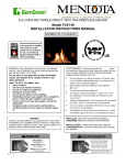
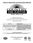
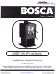
Installation and Operating Manual Model 5660 (I) Tested & Listed by Portland Oregon USA OMNI- Test Laboratories, Inc. Report #: 215-S-32-4 and 215-S-33-4 SAFETY NOTICE Please read this entire manual before installation and use of this pellet fuel-burning room heater. Failure to follow instructions may result in property damage, bodily injury, or even death. If your heater is not properly installed, a house fire may result. For everyone’s safety, follow all Installation and Operating Directions. Never use makeshift compromises during the installation of this appliance. Contact your local building or fire officials about restrictions and installation inspection requirements in your area. These Pellet Stove Room Heaters have been designed for use in the US and Canada and are suitable for mobile homes. The French version of this manual is available for download at www.usstove.com Save These Instructions United States Stove Company • 227 Industrial Park Road, South Pittsburg, TN 37380 • Phone #: (800) 750-2723 Part No.: 851901E TABLE OF CONTENTS Topic Page(s) Introduction ....................................................................................................................................................3 Safety Information .........................................................................................................................................4 Specifications ............................................................................................................................................... 6 Dimensions ................................................................................................................................................6-7 Operating Instructions ................................................................................................................................8-9 Thermostat Installation ................................................................................................................................10 Clearances to Combustibles ....................................................................................................................... 11 Installing Your Room Heater ..................................................................................................................12-19 Mobile Home Installations ..........................................................................................................................20 Insert Pellet Stove Installation ................................................................................................................21-24 Vent Termination Locations ........................................................................................................................25 Maintenance ..........................................................................................................................................26-29 Troubleshooting .....................................................................................................................................30-31 Wiring Diagram ...........................................................................................................................................32 Replacement Parts List ..............................................................................................................................33 Warranty Card .............................................................................................................................................35 2 Introduction The entire family of United States Stove Company thanks you for purchasing your new pellet burning room heater. At U.S. Stove, we build all of our products with a hands-on approach to detail and quality. Our old world team of Craftsmen take great pride in their superior workmanship to ensure you have years of trouble free use of your pellet heater. U.S. Stove Pellet Burning Room Heaters have been tested and listed for installation in residential, mobile home and alcove installations. U.S. Stove Pellet Burning Room Heaters are available in free standing pedestal and fireplace insert versions. U.S. Stove Pellet Burning Room Heaters have been certified by OMNI-Test Laboritories to: ASTM E1509-04, ULC/ORD-C1482-M90, ULC-S627-00, & ULC-S628-00 The performance of your Pellet Stove Room Heater can be affected by the type of pellet fuel you choose to burn in it. It is important to use only pellet fuel that is dry and free from dirt or other impurities. The Pellet Fuel Industry has established standards for wood pellet manufacturers. We recommend that pellet fuel used in all U.S. Stove Pellet Burning Room Heaters meet or exceed the following specifications: Fines (fine particles): Bulk Density: Size: Ash Content: Moisture Content: Heat Content: Maximum through a 1/8” screen Minimum 40 lbs per cubic foot Maximum 3/8” Diameter by 1-1/2” length 1% Maximum (Premium grade) 3% Maximum (Standard grade) 8% Maximum Minimum 8,200 btu’s per hour It is important to note that the ash content of the fuel and frequency of operation will determine the frequency of which you will be required to clean your Pellet Stove. A high ash fuel may result in daily cleaning, while a low ash content fuel may result in less frequent cleaning. Occasionally, impurities in the fuel will cause a hard mass build up in the burn pot of your Pellet Stove. Impurities, such as silica, can virtually form little glass balls when subjected to the high heat generated in the burn pot. When allowed to collect, a hard base build up may block air flow through the burn pot, which will significantly affect the performance and efficiency of your Pellet Stove. It is a good idea to check the burn pot for any hard mass buildup or other blockage on a daily basis, and if necessary let the burn pot cool and then clean the burn pot. U.S. Stove Company realizes that it cannot control the quality of pellet fuel you choose to use in your Pellet heater; U.S. Stove assumes no responsibility for that choice. CAUTION: BE SURE TO STORE PELLET FUEL A MINIMUM OF 3 FEET (914.5MM) AWAY FROM THE PELLET HEATER. RADIANT HEAT CAN IGNITE THE FUEL. Please note that the rating label is located on the inside of the hopper lid on freestanding models and on the back side of the ash pan cover for insert models. 3 SAFETY INFORMATION Be sure to read the entire owner’s manual prior to installing and operating this Pellet heater. Failure to follow these instructions could result in fire, property damage, bodily injury or even death. This stove’s exhaust system works with negative combustion chamber pressure and a slight positive chimney pressure, it is extremely important to ensure that the exhaust system is sealed and airtight. The ash pan and viewing door must be securely fastened in order for the unit to be airtight. This Pellet heater will not operate using natural draft or without a power source for the blowers. CAUTION: Burning fuel creates carbon monoxide and can be hazardous to your health if not properly vented. CAUTION: A working smoke detector must be installed in the same room as this product. It must be installed at least 15 feet (4,57 m) from the appliance in order to prevent undue triggering of the detector when reloading. The use of grates or other methods of supporting the fuel is not permitted. This Pellet heater is designed to burn pellet wood fuel only. Do not use any other type of fuel; doing so will void any warranties stated in this manual. THE USE OF SOLID WOOD FUEL IS PROHIBITED BY LAW. This Pellet heater is designed for residential installation according to current national and local building codes. It is also approved as a mobile home heater, which requires connection to an outside combustion air source. When installing a Pellet Stove in a mobile home, it must be electrically grounded to the steel chassis of the home and bolted to the floor. Make sure that structural integrity of the home is maintained. Make sure that structural integrity of the home is maintained when passing vent pipes through walls, ceilings and roofs It is recommended that the exhaust vent be cleaned bi-annually or after every two tons of pellets. Soot or creosote may accumulate when the pellet heater is operated under incorrect conditions, such as an extremely rich burn (black tipped lazy orange flames). Do not operate the stove if the flame becomes dark or sooty or if the burn pot overfills with pellets. Turn the stove off and call your dealer. The grounded electrical cord must be connected to a standard 120 volt, 60 hertz electrical outlet. Ensure that the electrical cord is not trapped under the appliance and that it is clear of any hot surfaces or sharp edges. The ash pan and viewing door must be locked securely for proper and safe operation. DO NOT PLACE UNBURNED OR NEW PELLET FUEL IN THE ASH PAN. A fire in the ash pan may occur. Do not operate your pellet heater if you smell smoke coming from it. Turn it off, monitor it and call your dealer. Repair and servicing of your U.S. Stove Pellet Burning Room Heater may only be done by a qualified technician. Disconnect the power cord before performing any maintenance or repair. NOTE: Turning the Pellet Stove Room Heater to "off" does not disconnect power from the unit. The Pellet Stove Room Heater will not operate during a power outage. If a power outage or tripped circuit occurs, check for smoke spillage and open windows or doors to ventilate as necessary. CAUTION DO NOT CONNECT TO OR USE IN CONJUNCTION WITH ANY AIR DISTRIBUTION DUCTWORK UNLESS SPECIFICALLY APPROVED FOR SUCH INSTALLATIONS. Know the symptoms of carbon monoxide poisoning: headache, dizziness, weakness, nausea, vomiting, sleepiness, and confusion. Carbon monoxide reduces the blood’s ability to carry oxygen. Low blood oxygen levels can result in loss of consciousness and death. See a doctor if you or others develop cold or flu-like symptoms while cooking or in the vicinity of this appliance. Carbon monoxide poisoning, which can easily be mistaken for a cold or flue, is often detected too late. Alcohol consumption and drug use increase the effects of carbon monoxide poisoning. Carbon monoxide is especially toxic to mother and child during pregnancy, infants, the elderly, smokers, and people with blood or circulatory system problems, such as anemia, or heart disease. 4 SAFETY INFORMATION - continued Keep foreign objects out of the hopper. Contact your local building officials to obtain a permit and information on any installation restrictions or inspection requirements in your area. Be sure to notify your insurance company of your new U.S. Stove Pellet Burning Room Heater. Allow the Pellet Stove Room Heater to cool before performing any maintenance. Ashes must be disposed of in a steel container with a tight lid and placed on a noncombustible surface well away from your home. Check the venting system, at least twice a year, for creosote build-up. Keep all door/lid seals and gaskets in good condition. Adequate ventilation air is required to operate this heater. During operation, the heater draws air for combustion which can be assisted by the installation of outside combustion air inlets. However, certain weather conditions such as icing or use of kitchen exhaust fans may impact and reduce the effectiveness of vents. It is important to note that room air starvation will negatively impact the operation of the heater. If power outages with battery backup or room air starvation occurs during operation of heater, smoke in the house may result. This may trigger smoke detectors if they are installed. CAUTION: DO NOT CONNECT TO ANY AIR DISTRIBUTION DUCT OR SYSTEM. DO NOT USE CHEMICALS OR FLUIDS TO START THE FIRE. NEVER USE GASOLINE, GASOLINE TYPE LANTERN FUEL, KEROSENE, CHARCOAL LIGHTER FLUID, OR SIMILAR LIQUIDS TO START OR FRESHEN UP A FIRE IN THE HEATER. KEEP ALL SUCH LIQUIDS WELL AWAY FROM THE HEATER WHILE IT IS IN USE. USING THESE CHEMICALS COULD CAUSE BODILY HARM, HEATER DAMAGE AND WILL VOID THE WARRANTY. DO NOT BURN GARBAGE OR FLAMMABLE FLUIDS SUCH AS GASOLINE, NAPHTHA OR ENGINE OIL. HOT WHILE IN OPERATION. KEEP CHILDREN, CLOTHING AND FURNITURE AWAY FROM THE HEATER. CONTACT MAY CAUSE SKIN BURNS. YOUNG CHILDREN SHOULD BE SUPERVISED WHEN THEY ARE IN THE SAME ROOM AS THE STOVE. DO NOT ATTEMPT TO OPERATE THE HEAT EXCHANGER VENT TUBE CLEANER WHILE THE PELLET STOVE IS IN OPERATION OR COOLING DOWN; WAIT UNTIL PELLET STOVE HAS COOLED COMPLETELY BEFORE PERFORMING THIS PROCEDURE. ENSURE THAT PEOPLE ARE AWARE THAT THE HEAT EXCHANGER VENT TUBE CLEANER KNOB WILL BE VERY HOT DURING PELLET STOVE OPERATION AND CAN BE A BURN HAZARD. OTHER RADIANT SURFACES OF THE STOVE WILL BE HOT DURING OPERATION AND CAN BE A BURN HAZARD. A working smoke detector must be installed in the same room as this product. It must be installed at least 15 feet (4,57 m) from the appliance in order to prevent undue triggering of the detector when reloading. 5 SPECIFICATIONS Heating Specifications: Burn Rate: Hopper Capacity: *43,900 btu’s per hour or 5.1 lbs. of fuel per hour 55 lbs. *Dependent upon quality and heating value of pellet fuel. DIMENSIONS Figure 1 30.50 in [774.6 mm] 26.19 in [665.2 mm] 24.25 in [615.9 mm] 6.00 in [152.4 mm] 13.70 in [348 mm] 20.50 in [520.8 mm] 10.50 in [266.6 mm] 6 DIMENSIONS - continued The minimum installation dimensions, of the insert opening, are: 32” (813mm) wide x 22-3/4” (578mm) high x 12-1/4” (311mm) deep. Figure 2 7 OPERATING INSTRUCTIONS Check and Fill the Fuel Hopper with Pellets: This Pellet Stove is available as a freestanding unit or as a fireplace insert. There is a different method for filling the hopper for each type of heater: To check and fill the hopper of the freestanding heater, simply lift the hopper door, visually check the hopper and add pellets when needed. To check and fill the hopper of the insert heater, pull hopper lid forward, visually check the hopper and add pellets when needed. CAUTION: DO NOT OVERFILL THE PELLET FUEL HOPPER. AS A SAFETY PRECAUTION, AUGER WILL NOT OPERATE AT ANY TIME WHEN FUEL HOPPER DOOR IS OPEN. Pre-start Check-up: Make sure that all parts of the pellet stove room heater are cool before proceeding. Remove the burn pot and clean out any ash debris. Be sure to re-install the burn pot in the correct position (see page 8). The blowers and automatic fuel supply are controlled from a panel located on the right hand side of the stove. Note: Your Pellet Stove may omit an odor as oil residue from the manufacturing process burns off and the high temperature paint cures. You can minimize this effect by running a smaller fire for the first few hours of operation. Avoid placing any items on the stove top during this period as the stove’s paint could be permanently damaged. Lighting Instructions: ATTENTION: Viewing door must be securely latched to ensure proper stove operation. Push door closed and engage latches in locking holes on door. Press latch handles toward stove body until fully engaged; you will feel the latch engage and hear an audible click. If door is loose adjust tension control nuts on latches until both latches hold door secure and tight. When first operating your Pellet Stove, depress the MODE button until the LED indicator above MANUAL lights up. This will engage MANUAL mode and provide you with full control of the heater’s control board functions and allow you to familiarize yourself with how the heater works. The heat level for T-STAT mode can only be set when the control is in the Manual Mode. Starting Up The Pellet Stove Room Heater: Whenever operating the pellet stove for first time, or if the stove runs out of pellets, it is necessary to prime the auger with pellet fuel. To do this, Press and Hold the AUGER Button for Approximately 3 Seconds until the AUGER LED illuminates. This procedure will prime the auger and then automatically initiate the normal ignition cycle. CAUTION: Do not use this procedure for normal startup. To do so would cause excessive fuel build-up in the burn pot. For normal startup with pellet fuel in the auger, press and release the On/Off button. The LED indicator light above the On/Off button will alternately flash green then red to indicate that the start-up cycle has begun. The light above the Auger button will flash intermittently to indicate the activation of the auger feeding the pellets into the burn pot. The electric igniter will also be activated at this time. The igniter takes a few minutes to come up to temperature in order to ignite the pellets in the burn pot. It will normally take between 4 minutes and 8 minutes for pellets to ignite. NOTE: If pellets do not ignite within 12 minutes the heater will shut down, requiring you to turn on the heater and repeat the start-up process. When the pellets have ignited and flame has been established, the start-up cycle will end; this procedure takes between 8 and 12 minutes. If the control is set to Manual Mode, it will now default to the heat level setting the last shutdown time. If the control is set to T-STAT Mode, the heat output will coincide to the commands from the thermostat. Auger: As explained in the starting up step, this button is only served to start up the pellet stove in lieu of the on/off button when there are no pellets in the auger. Circulation Air Flow: Your pellet stove room heater features circulation air flow which will change in accordance with the heat setting. Circulation air flow will be at its maximum setting when the heat setting is also at maximum and subsequently will be at its minimum setting when the heat setting is at minimum. If you desire to operate the circulation fan at its maximum setting regardless of heat setting, you may do so by pressing the FAN button. Auger Trim: When operating at Heat Level 1, if the flame goes out or the heat output is too high on the minimum heat level setting, use the AUGER TRIM button to make adjustments. See the AUGER TRIM button description on page 8. Shutting Down Your Pellet Stove Room Heater: Turn off the heater by pressing the On/Off button. The stove will enter the shutdown cycle and the pellets will stop feeding into the burn pot to allow the fuel in the burn pot to be combusted and consumed. During this period, the exhaust blower and circulation fan will continue to operate until the flames are out and the heater has cooled down. When the heater has cooled down to its pre-set level, it will shut down completely. CAUTION: NEVER TURN OFF THE HEATER BY UNPLUGGING OR DISCONNECTING ITS ELECTRICAL POWER SOURCE. DOING SO WILL CAUSE THE HEATER TO SKIP THE PROPER SHUTDOWN CYCLE, CAUSING THE HEATER TO OVERHEAT AND THE POSSIBLE RELEASE OF SMOKE INTO THE HOUSE. 8 OPERATING INSTRUCTIONS - continued Control Board Functions: MODE Button: The MODE button allows you to switch operating mode on your pellet stove room heater. Depress the MODE button to switch between Manual and T-STAT modes. As you depress the MODE button, the indicator light above the desired mode will engage. When you engage the Manual mode, you will be able to manually select the heat settings. If you have installed a remote thermostat for your heater and wish to have the heater controlled by that thermostat, depress the MODE button to engage T-STAT mode. The thermostat will control the heat output of the heater alternating between the lowest heat level and the highest heat level that you have pre-selected. The T-STAT mode provides the most even heat output, for better comfort, and to extend the life of the pellet fuel ignition system. Additionally, the constant flame serves as a warning for people and pets to keep away from the heater while it is in operation. ON/OFF Button: The ON/OFF button is used to turn the heater on and off. Whenever there is power to the heater, the LED indicator light above the ON/OFF button will be solid red. If the heater is cold prior to start-up, press and release the ON/OFF button. The LED light above the ON/OFF button will alternately flash red and green to indicate the startup cycle has started. Fuel pellets will start to feed into the burn pot and the pellet fuel ignition system will be activated. Flames in the burn pot will normally appear between 4 - 8 minutes, and once the flame has been established, the startup cycle will end, this takes between 8-12 minutes. At this point the LED indicator light above the ON/OFF button will glow solid green. The user will now be able to make heat level adjustments. Figure 3 HEAT LEVEL Button: Depress the HEAT LEVEL button to advance the heat level by one level until you reach the maximum setting; from the maximum level you will decrease one level each time you depress the HEAT LEVEL button. The circulation fan speed will also increase with the heat level setting. Wait until the startup cycle is complete and the ON/OFF LED is solid green to set Heat Level. (The HEAT LEVEL LEDs are also used as codes to indicate a malfunction, please refer to the Safety Features and warning codes section for more information.) FAN Button: Depressing the FAN button will set the circulation fan speed to high, overriding the automatic fan speed control. The onboard logic will modulate the fan speed in accordance with the heat level setting. It is recommended that you allow the control to automatically set and adjust the speed of the fan to obtain optimum efficiency and minimal fan noise. AUGER Button: Whenever Operating the Pellet Stove for First Time, or if The Stove Runs Out Of Pellets, it is Necessary to Prime the Auger with Pellet Fuel. To do this, Press and Hold the AUGER Button for Approximately 3 Seconds until the AUGER LED illuminates. This Procedure will prime the Auger and then Automatically Initiate the Normal Ignition Cycle. NOTICE: Do not use this procedure for normal startup. To do so would cause excessive fuel build-up in the burn pot. AUGER TRIM Button: This Button is only enabled when operating at Heat Level 1. Depress the AUGER TRIM Button to change the Auger feed rate on the minimum heat level to account for the quality of pellet fuel being used. Increasing the Auger feed rate will help keep the flames from extinguishing on the minimum heat level setting. You can also use the AUGER TRIM button to lower heat output on the minimum heat level setting: Depress and release the AUGER TRIM button until the heat level 1 and 5 setting lights appear to slightly increase the feed rate on the minimum heat level. Depress and release the AUGER TRIM button until the heat level 1 and 4 setting lights appear to slightly reduce the pellet feed rate on the minimum heat level setting. Use this setting to reduce the heat level output on low. Depress and release the AUGER TRIM button until only the heat level 1 setting light is on, this is the factory setting and works for most types of fuel. Open Door: During normal operation the heater will automatically shut off if the viewing door is opened for more than 30 seconds. This action causes the heater to go into vacuum error mode. To clear this error and restart the heater, close the door, depress the ON/OFF button and then follow directions for restarting heater. Refilling the Fuel Hopper: For maximum performance do not let the pellet fuel hopper drop below 1/4 full. Fuel Hopper Lid Safety Switch: When the Fuel Hopper Lid is opened the auger will stop turning to prevent accidental injury. KEEP PELLET FUEL HOPPER LID CLOSED AT ALL TIMES EXCEPT WHEN REFILLING. DO NOT OVERFILL HOPPER. Safety Features and warning code: 1. Your heater is equipped with a temperature “high-limit” switch, designed to shutdown the auger in case of an over temperature situation. The high-limit switch is a thermo snap disc type and must be manually reset in the event of an overheat shutdown. Once the heater has cooled down, you can reactivate the high-limit switch by depressing the manual reset button located on the high-limit switch. 2. When the High-Limit switch opens, which indicates an overheat failure, the HEAT LEVEL LED’s 3 & 4 will flash red. 3. Your heater is equipped with a vacuum switch that automatically shuts down the auger in the event of a exhaust fan malfunction. 4. When a Vacuum Error is sensed, the HEAT LEVEL LED’s 1 & 2 will flash red. Check to ensure the glass door is latched properly. 5. When the Low-Limit switch opens, (fire went out) the HEAT LEVEL LED’s 4 & 5 will flash red. First check fuel supply, then check to ensure Auger is not jammed and finally that pellet hopper door is properly closed. 6. When the Pellets in the Burn Pot fail to ignite HEAT LEVEL LED’s 1 & 5 will flash red. NOTE: In the event that the high-limit switch or vacuum switch activates, please contact your dealer to discuss the cause of this activation and to ensure that your heater continues to operate in a safe manner. Either switch tripping can indicate a problem with the operation of your heater. 9 THERMOSTAT INSTALLATION Optional thermostats are available for use with your pellet stove. A thermostat can help you maintain a constant room temperature. The thermostat option will require the installation of a millivolt type thermostat. NOTE: Your thermostat should be installed by an authorized dealer or service person. Installation of Remote Thermostat: • Disconnect Pellet Stove Room Heater unit from power supply. • Open right side panel to gain access to rear of control panel. • Strip insulation from thermostat wires and connect to the screw terminal on the rear of the control panel (see Figure 4). If you have installed a remote thermostat for your pellet stove and wish to have the heater controlled by that thermostat, depress the MODE button to engage T-STAT mode. The thermostat will control the heat output of the heater alternating between the lowest heat level and the highest heat level that you have pre-selected. The T-STAT mode provides the most even heat output, for better comfort, and to extend the life of the pellet fuel ignition system. Additionally, the constant flame serves as a warning for people and pets to keep away from the heater while it is in operation. Figure 4 Connection Terminal for External Thermostat Left: GND Middle: Thermostat Right: 5V power source 10 CLEARANCES TO COMBUSTIBLES INSTALL ALL VENTS AT CLEARANCES SPECIFIED BY THE VENT MANUFACTURER! When your Pellet Stove Room Heater is being installed on a combustible floor it is mandatory that a 1/2” (13mm) thick noncombustible hearth pad be installed under the heater. The non-combustible hearth pad must extend at least 6” beyond the fuel loading and ash removal openings and at least the depth of the heater plus 6 inches (152mm) out in front of the heater. This applies to both freestanding heaters and insert heaters. 2” BACK WALL 2” Figure 5 6” FLOOR PROTECTION USA 6” CANADA 8” USA 6” CANADA 8” FLOOR PROTECTION USA 6” CANADA 18” USA 6” CANADA 18” Figure 6 Alcove Dimensions 36” 35” 40” 11 INSTALLING YOUR ROOM HEATER You have already made the important decision of choosing your U.S. Stove Pellet Burning Room Heater; now your next step is to determine where to install your new pellet stove heater. To get the most efficient use of re-circulated heat, you should consider a room that is centrally located within your home. Choose a room that is large and open. It is Extremely Important to maintain proper clearances from any combustible surfaces or materials in the room where your heater will be located. You can find proper clearance measurements on page 12 of this manual and on the rating label of your pellet stove. The pellet stove can be vented through an exterior wall or into an existing masonry or metal chimney. The chimney must be lined if it is over 6” (150mm) in diameter or if it has a cross-sectional area of over 28 square inches (711mm2). Venting can pass through the ceiling and roof if approved pipe is used. Where passage through a wall, or partition of combustible construction is desired, the installation must conform to CAN/CSA-B365 DO NOT OBTAIN COMBUSTION AIR FROM THE ATTIC, GARAGE OR ANY OTHER UNVENTILATED AREA. YOU MAY OBTAIN COMBUSTION AIR FROM A VENTILATED CRAWLSPACE. DO NOT INSTALL A FLUE DAMPER IN THE EXHAUST VENTING SYSTEM OF THIS UNIT. DO NOT CONNECT THIS UNIT TO A CHIMNEY FLUE SERVING ANOTHER HEATER, FURNACE OR APPLIANCE. INSTALL VENT AT CLEARANCES SPECIFIED BY THE VENT MANUFACTURER. ONLY USE APPROVED MATERIAL FOR INSTALLATION, FAILURE TO DO SO MAY RESULT IN PROPERTY DAMAGE, BODILY INJURY, OR EVEN DEATH. This appliance is certified for use with listed 3 inch or 4 inch “PL” or “L” pellet venting products as well as Selkirk’s DirectTemp Vent system for pellet burning appliances. The use of other components other than stated herein could cause bodily harm, heater damage, and void your warranty. HORIZONTAL EXHAUST VENT INSTALLATION 1. Locate your pellet stove in a location which meets the requirements of this manual, but in an area where it does not interfere with the house framing, wiring, etc. 2. Install a non-combustible hearth pad underneath the pellet stove. This pad should extend at least 6” (152mm) in front of the unit. 3. Place the pellet stove approximately 15” (381mm) away from the interior wall. 4. Locate the center of the exhaust pipe of your unit. This point should then be extended to the interior wall of your house. Once you have located the center point, on the interior wall, cut a 7” (175mm) diameter hole through the wall. 5. The next step is to install the wall thimble, refer to the instructions which come with the wall thimble for this step. 6. Install the appropriate length of exhaust vent pipe into the wall thimble. See steps 11 and 12 when determining the correct length of exhaust vent to use. 7. Outside Fresh Air is Mandatory when installing this pellet stove room heater in airtight homes and mobile homes. Be sure that the outside air vent has an approved cap on it to prevent rodents from entering. Be sure to install in location that won’t become blocked with snow, etc. 8. The air intake pipe is equipped with a butterfly valve that is preset to maximum air intake. For optimum operating efficiency you may calibrate the butterfly valve to provide less intake air. (See Figure 7) Caution: Too much restriction on the intake air will cause dirtier burn, therefore, will require more frequent cleaning. 9. Connect the exhaust vent pipe to the exhaust outlet of your pellet stove. 10. Secure all vent joint connections with 3 screws. Seal the exhaust vent joint connections with high temperature silicone sealant. 11. Push the unit straight back to the interior wall, being sure to maintain the minimum clearances to combustibles 6” (152mm) to the back of the unit. Seal the annular space of the wall thimble and around the vent pipe with high temperature silicone sealant. 12. The exhaust vent pipe must extend at least 12” (300mm) out past the exterior wall. Seal the annular space of the wall thimble and around the vent pipe with high temperature silicone sealant. 13. Install an approved horizontal termination cap or if necessary install a 90° elbow and appropriate length of vertical venting. An approved vertical vent cap is recommended. 12 INSTALLING YOUR ROOM HEATER - continued HORIZONTAL EXHAUST VENT INSTALLATION Figure 8 Listed Horizontal Cap Exhaust Vent Combustion Air Intake with approved cap Wall Thimble Mfg. by Pellet Vent Mfg. 6” (152mm) Clearance to Combustibles Floor Protector 6” (152mm) Clearance Front Figure 9 6” (152 mm) Clearance Wall to Back of Unit Wall Thimble Exhaust Vent 45 Elbow or Listed Termination Rodent Mesh Cap 6” (152 mm) Combustion Air Intake with approved cap 12” (300mm) Non-Combustible Floor Protection Existing Floor (Combustible) 13 INSTALLING YOUR ROOM HEATER - continued FREESTANDING INTERIOR VERTICAL INSTALLATION 1. Locate your Pellet Stove Room Heater in a location which meets the requirements of this manual, but in an area where it does not interfere with the house framing, wiring, etc. 2. Install a non-combustible hearth pad underneath the pellet stove. This pad should extend at least 6” (152mm) in front of the unit. 3. Place your Pellet Stove Room Heater on the hearth pad and locate the unit in a manner that will leave the exhaust vent with a minimum of 3” (75mm) clearance to any combustible wall. 4. When installing the air intake, locate the center of the combustion air intake pipe at the back of your unit. Line up the center with the same spot on your exterior wall and cut a 2-1/2” (64mm) diameter hole through the wall. 5. Secure all vent joint connections with 3 screws. Seal the exhaust vent joint connections with high temperature silicone sealant. 6. Install the combustion air intake pipe. 7. Install a tee, with a cleanout, on the exhaust pipe found at the rear of your unit. 8. Install approved vent upward through the ceiling. When you pass through the combustible framing ensure that the appropriate ceiling fire stop is used. You must maintain a minimum 3” (75mm) clearance to combustibles and keep any insulation away from the exhaust vent. 9. Extend the exhaust vent through the roof flashing and ensure that the vertical cap is approximately 36” (900mm) above the roof. Listed Termination Flashing 36” (900 mm) 3” (75 mm) Clearance to Combustibles Use Ceiling Firestop Use Ceiling Firestop 3” 3” (75mm) Clearance (75mm) Clearance to to Combustibles Combustibles 3” (75 mm) Tee with Cleanout 6” (150 mm) 6” (150 mm) Non-Combustible Floor Protection Combustion Air Intake with approved cap Existing Combustible Floor 14 Figure 10 INSTALLING YOUR ROOM HEATER - continued FREESTANDING EXTERIOR VERTICAL INSTALLATION 1. Locate your Pellet Stove Room Heater in a location which meets the requirements of this manual, but in an area where it does not interfere with the house framing, wiring, etc. 2. Install a non-combustible hearth pad underneath the pellet stove. This pad should extend at least 6” (152mm) in front of the unit. 3. Place your Pellet Stove Room Heater on the hearth pad and locate the unit in a manner that will leave the exhaust vent with a minimum of 3” (75mm) clearance to any combustible wall. 4. If installing the optional air intake, locate the center of the combustion air intake pipe at the back of your unit. Line up the center with the same spot on your exterior wall and cut a 2-1/2” (64mm) diameter hole through the wall. 5. Secure all vent joint connections with 3 screws. Seal the exhaust vent joint connections with high temperature silicone sealant. 6. Locate the center of the exhaust pipe, at the back of the unit. Line up the center with the same spot on the exterior wall a cut a 7” (178mm) diameter hole through the wall. 7. Install the wall thimble; (refer to the instructions which come with the wall thimble). 8. Install an approved exhaust vent through the wall; be sure to make sure that 3” (75mm) clearances to combustibles are maintained. 9. Secure all vent joint connections with 3 screws. Seal the exhaust vent joint connections with high temperature silicone sealant. 10. Install a Tee with a cleanout on the end of the exhaust pipe and then install approved venting upward from there. Be sure to install support brackets every 5’ (1525cm) to keep the venting straight and secure. 11. Extend the exhaust vent through the roof flashing and ensure that the vertical cap is approximately 36” (900mm) above the roof. Listed Termination Figure 11 Flashing 36” (900 mm) 6” (150 mm) Clearance 3” (75 mm) Clearance Wall Thimble Tee w/ Cleanout 6” (150mm) Support Bracket Non-Combustible Floor Protection Existing Combustible Floor Combustion Air Intake with approved cap 15 INSTALLING YOUR ROOM HEATER - continued SELKIRK DIRECT-TEMP VENT SYSTEM FOR PELLET STOVE HEATERS Images courtesy of Selkirk 16 INSTALLING YOUR ROOM HEATER- continued SELKIRK DIRECT-TEMP VENT SYSTEM FOR PELLET STOVE HEATERS Images courtesy of Selkirk UP AND OUT HORIZONTAL TERMINATION KIT FIGURE 12 17 INSTALLING YOUR ROOM HEATER- continued SELKIRK DIRECT-TEMP VENT SYSTEM FOR PELLET STOVE HEATERS Images courtesy of Selkirk STRAIGHT OUT HORIZONTAL TERMINATION KIT FIGURE 12 18 INSTALLING YOUR ROOM HEATER - continued SELKIRK DIRECT-TEMP VENT SYSTEM FOR PELLET STOVE HEATERS Images courtesy of Selkirk THROUGH THE ROOF VERTICAL TERMINATION KIT FIGURE 14 19 MOBILE HOME INSTALLATION Mobile home installation should be done in accordance with the Manufactured Home and Safety Standard (HUD), CFR 3280, Part 24. Canadian installations require that the heater must be connected to a 3 or 4 inch, factory-built chimney conforming to CAN/ULC-S629. See the installation illustrations in this manual for minimum height above the roof. U.S. Stove suggests the use of Selkirk’s Pellet Venting Products. Refer to their installation instructions for proper installation of the exhaust and combustion air intake. The chimney installation must allow for removal in case of mobile home transportation, especially outside connections. You may contact your local building authority or person having jurisdiction on height restrictions. In order for this unit to be installed in a mobile home the following criteria must be met: • The unit must be secured to the floor using lag bolts in the holes provided in the pedestal base. • Ensure that the unit is permanently electrically grounded to the chassis of your home. • All exhaust systems must have a spark arrestor. IT IS MANDATORY TO TAKE THE COMBUSTION AIR FROM THE OUTSIDE WHEN INSTALLING THIS UNIT IN AIR TIGHT OR MANUFACTURED/MOBILE HOMES. CAUTION: THE STRUCTURAL INTEGRITY OF THE MANUFACTURED HOME FLOOR, WALL, AND CEILING/ROOF MUST BE MAINTAINED. MAKE SURE TO MAINTAIN AN EFFECTIVE VAPOR BARRIER BY SEALING WITH SILICONE WHERE THE CHIMNEY OR OTHER COMPONENTS PENETRATE TO THE EXTERIOR OF THE STRUCTURE. REFER TO AND FOLLOW THE CHIMNEY MANUFACTURER’S INSTALLATION INSTRUCTIONS. WARNING: DO NOT INSTALL IN SLEEPING ROOM. Figure 15 HEARTH PAD FLOORING STEEL FRAME GROUND WIRE, DIRECTLY TO METAL CHASSIS 1/4” LAG BOLTS, SECURELY FASTENED NOTE: Only the freestanding model is approved for installation into a mobile home. 20 INSERT PELLET STOVE INSTALLATION U.S. Stove Pellet Burning Room Heaters are also available as an insert into existing masonry of factory-built fireplaces. Do not alter the existing fireplace in any way either by removing bricks and mortar which could weaken the structural integrity of the fireplace. There is a small amount of assembly required when installing this model. The steps are as follows: Note: The shroud must be installed before unit is set into its final position. Step 1: Shroud Side: Facing the back of the unit take the left shroud side piece (no control panel hole) and fasten, as shown, with 2 screws provided. Screw Here Figure 16 Screw Here Step 2: Shroud Side: Facing the back of the unit take the right shroud side piece (with control panel hole) and fasten, as shown, with 2 screws provided. Screw Here Figure 17 Screw Here 21 INSERT PELLET STOVE INSTALLATION - continued Step 3: Shroud Top: Facing the back of the unit take the top shroud side piece and fasten, as shown, with 4 screws provided. Screw Here Screw Here Screw Here Screw Here Step 4: Control Board: Take the control board and insert it from the back of the right shroud side (facing front of unit). Fasten control board in place with 4 screws provided (top & bottom of board). Control Board 22 INSERT PELLET STOVE INSTALLATION - continued Minimum Clearance to Combustibles and Floor Protection SIDE WALL MANTEL 10” TOP TRIM 5” SIDE TRIM 10.5” 16” 6” 6” FLOOR PROTECTOR Figure 20 A: Side wall: 16” to side of appliance B: Top Trim: 5” above top of appliance C: Side trim: 10.5” to side of appliance D: Mantle: 10” above top of appliance Floor Protection When in MASONRY fireplaces, use ½ inch thick non-combustible material. When in Factory-built fireplaces, use a 1 inch, non-combustible surface with a k factor of 0.84. For multiple layers, add R-values of each layer to determine the overall R-value. The R value for the required board is 1.2. Convert specification to R-value: k-factor is given with a required thickness (T) in inches: R=1/k x T. The C-factor is given: R=1/C Example: If the floor protector is 4” brick with a C-factor of 1.25 over 1/8” mineral board with a “k” factor of 0.29 the total R-value of the system is: 4” brick C=1.25, R=1/1.25=0.8 1/8” mineral board K=0.29, R=1/0.29 x 0.125=0.431 Total R = Rbrick + Rmineral = 0.8 + 0.431 = 1.231 Total R is greater than 1.2, the system is acceptable. 23 Installation into a Masonry Fireplace: Air Inlet Exhaust Cap 1. Your chimney must be inspected by a certified chimney sweep or installer to determine its structural condition. Steel Plate or Flashing 2. Measure amount of venting required to top chimney plus 14” to ensure the termination is adequate distance above the roofline. Rigid Vent Pipe Damper Removed or Fastened Open (for Canada) or sealed Flexible Exhaust Vent 3. The first 5’ of exhaust will be Simpson Dura Vent pellet stove flex vent; the remainder uses rigid pipe. For each joint subtract 1-1/2” to allow for the overlap. You may need an adjustable length section to achieve the correct height. The air intake may be 2” aluminum flex vent. 4. Assemble the first rigid section of exhaust pipe to the flex vent pipe insuring that the “UP” arrows shown on the pipe labels are pointing up. Connect sections and twist to lock. Repeat the process for the remainder of the pipe sections and lower the assembly down the chimney. Lower the intake and exhaust pipes below their normal position to connect the pipe to back of heater. Tie a line to the top section of venting to pull it back up to the correct position. 5. Connect to the exhaust of the stove by installing a pipe adapter to the exhaust fan and either a 90º elbow or a clean out tee with cap. The air intake can be attached to the heater with a hose clamp. 6. Connect the heater to the coupling on the bottom of the exhaust flex vent and twist to the locked position. Push the heater into the fireplace to its final position. Mantle 7. From the top of the chimney, pull the vent system up to the desired height. 8. For the exhaust termination of the pellet vent use a tall cone flashing and a storm collar. This requires 14” of pipe above the top of the masonry chimney. Pull the pipe up through the flashing to the desired height and mark where the storm collar will go. Slip the storm collar down over the pipe and fasten it to the pipe with a 1/4” stainless steel sheet metal screw. The storm collar will then support the entire exhaust vent system. 90º Elbow or Clean-Out Tee Minimum 6” (150 mm)noncombustible Floor Protection 9. Install the air intake vent through the chimney cap by cutting a hole and install cap as shown or attach air intake vent to a flashing and cap. The chimney top must be properly sealed to prevent rain and or snow from entering the chimney. 10. Install the cap and seal around the joint of the storm collar and any other joints that are visible. Perform these instructions in reverse if the removal of this appliance is ever needed for maintenance or repair. 24 VENT TERMINATION LOCATIONS Figure 22 25 MAINTENANCE FAILURE TO CLEAN AND MAINTAIN THIS UNIT AS INDICATED MAY RESULT IN POOR PERFORMANCE AND HAZARDOUS SITUATIONS. CLEAN THE HEATER FREQUENTLY AS ACCUMULATION OF SOOT, CREOSOTE OR FLYASH MAY OCCUR. NEVER CLEAN THE UNIT WHEN HOT. Burn Pot: Note: Let the unit cool to room temperature before inspecting the burn pot. Inspect the burn pot regularly to check that the holes have not become plugged. If necessary clean thoroughly. It is imperative that the burn pot be reinstalled the correct way or the unit will not light. The end of the burn pot with an igniter hole in it (see Figure 23) must be installed facing the rear of the unit. This hole allows the igniter to heat up the pellets to the point of ignition. Figure 23 Igniter Hole Figure 23 Burn Pot Removed Ash Pan Door 26 MAINTENANCE - continued Ash Removal - Freestanding Unit: Remove the ashes periodically to avoid unnecessary ash build up. Ash removal is as follows: 1. Let fire run out and allow unit cool to room temperature 2. Clean the heat exchanger tubes (see Heat Exchanger Cleaning section) – Make sure Pellet Stove is at room temperature before touching 3. Open the ash pan door, remove the burn pot and empty into metal container 4. Vacuum to remove ashes from the firebox. BE SURE THAT ASHES ARE COOL TO THE TOUCH BEFORE VACUUMING. Some vacuum cleaners may leak ash into the room. Your vacuum cleaner should have a special filter or bag to eliminate leakage. 5. Remove ash pan and dispose of ashes into metal container 6. Reinstall ash pan 7. Reinstall burn pot. Ash Removal - Insert Unit: Figure25 Ash Pan Door 1. Allow Heater to cool to room temperature 2. Lift the ash pan door up and pull out 3. Follow directions for freestanding unit above on this page. Disposal of Ashes Ashes should be placed in a steel metal container with a tight fitting lid. The closed container of ashes should be placed on a non-combustible floor or on the ground well away from all combustible materials, pending final disposal. If the ashes are disposed of by burial in soil or otherwise locally dispersed, they should be retained in the closed container until all cinders have been thoroughly cooled. Do not place other waste in the same container. 27 MAINTENANCE - continued Cleaning Heat Exchanger Tubes – Your Pellet Stove Room Heater is designed with a built in heat exchanger tube cleaner. This should be used every 2 or 3 days to remove ash build up on the heat exchanger tubes, which can reduce heat transfer. The handle, for the heat exchanger tube cleaner, is located in front of the vent tubes on front side of heater. Slide the rod front to back several times to clean the tubes then follow the instructions for ash removal. Gasket Figure 26 Heat Exchanger Cleaner Handle Periodically remove the clean outs on either side of the heat exchanger. Clean out the ash, then follow the instructions for ash removal. Check the gasket before replacing the clean out cover. If gasket is damaged new gasket can be ordered. Alternatively, high temperature silicone can be used to ensure a proper seal between the clean out cover and the stove body. Cover WARNING: DO NOT ATTEMPT TO OPERATE THE HEAT EXCHANGE TUBE CLEANER WHILE THE PELLET STOVE IS IN OPERATION OR COOLING DOWN; WAIT UNTIL PELLET STOVE HAS COOLED COMPLETELY BEFORE PERFORMING THIS PROCEDURE. Fans – DANGER: RISK OF ELECTRIC SHOCK. DISCONNECT POWER BEFORE SERVICING UNIT Over time ash or dust may accumulate on the blades of the circulation & exhaust fans. The fans should be inspected, periodically, and if any accumulation is present vacuumed clean as the ash or dust can impede the fans performance. It is also possible that creosote may accumulate in the exhaust fan therefore, this must be brushed clean. The exhaust fan can be found behind the left side panel (facing the front of the heater), the circulation fan can be found behind the right side panel. To access the igniter, remove the air inlet tube and cover (2 screws) (Figure 27). Note: When cleaning, take care not to damage the fan blades. Auger Motor Circulation Fan Exhaust Fan Figure 27 Ignitor 28 MAINTENANCE - continued Chimney/Vent System Cleaning: 1. Soot/Creosote Formation – When wood products are burned slowly, they produce tar and other organic vapors which combine with expelled moisture to form soot. The soot vapors condense in the relatively cool chimney flue, as a result, soot/creosote residue accumulates on the chimney lining. When ignited, soot/creosote makes an extremely hot fire which can damage the chimney or cause a house fire. If a soot/creosote fire occurs, shut down the heater immediately and call the fire department. 2. Soot and Flyash: Formation and Need for Removal—The products of combustion will contain small particles of flyash. The flyash will collect in the exhaust venting system and restrict the flow of the flue gases. Incomplete combustion, such as occurs during startup, shutdown, or incorrect operation of the room heater will lead to some soot formation which will collect in the exhaust venting system. The exhaust venting system should be inspected at least once every year or per ton of fuel burned to determine if cleaning is necessary. Door Gaskets: Gaskets around the door and window panes should be inspected, cleaned and repaired when necessary to maintain good seal. Door Glass Removal and Replacement: Do not attempt to operate the unit with broken glass. Replacement glass may be purchased from your U.S. Stove Pellet Burning Room Heater Dealer. If glass is broken, follow these removal procedures: Replacement glass must be 0.197” thick tempered ceramic glass with a working service temperature of 1400 deg. F. Center Glass size: 10” x 10.67”. Side glass size: 4” x 10.67” 1. 2. 3. 4. 5. Once the heater has cooled, remove the door from the heater. Remove the rope gasket from the door followed by the eight(8) nuts holding the glass retainer in place. While wearing gloves, carefully remove any loose pieces of glass from the door frame. Replace the glass and gasket, making sure the gasket runs the full perimeter of the glass edge. Re-install the retainer and eight nuts and rope gasket using high temperature silicone to adhere the gasket to the door. 6. Never use substitute materials for the glass. Glass Cleaning: (Clean as needed) 1. Do not attempt to clean the glass while unit is hot. Wait until the pellet heater has cooled and then use a soft cotton cloth and mild window cleaner or gas and wood stove cleaner. 2. Do not use abrasive cleaners. 3. Do not abuse the glass by striking or slamming the door. Task Maintenance Schedule Burn Pot Combustion Chamber Heat Exchanger Tubes Ash Pan Convection Fan Blades Combustion Fan Blades Hopper Venting System Glass Gaskets check daily weekly bi-weekly bi-weekly or every 10 bags of fuel annually annually bi-weekly or every 10 bags of fuel annually as needed anually 29 TROUBLE SHOOTING See figure 26, page 33, for component locations. The heater will not light. • Check that the heater is plugged in and that the wall outlet has power. • Unplug the unit then check all electrical connections against the Wiring Diagram in this manual. • Check the fuse on the circuit board. • If a thermostat is used, ensure it is calling for heat. • If your heater still does not light, contact your local dealer for service. The heater will not operate when hot. • Check that the fuel hopper has enough pellets. • Check that the combustion air inlet is not blocked. Insufficient air supply may cause the fire to burn cold and may cause fuel build up, in the pot, and smother the fire. • Check that the exhaust fan is operating. If the fan is not operating properly, it may not generate enough vacuum in the firebox. • Check the 200°F high limit switch. This switch is manually reset. Check if it has tripped. If so, let cool and reset switch. Check for cause of overheating. If switch trips again, contact your local dealer for service • Check the vacuum switch by shorting out the vacuum switch then depress ON/OFF button to “OFF” and back to “ON”. If the unit starts to operate change the vacuum switch. • Check the exhaust temperature switch (located on the exhaust blower) by shorting out the exhaust temperature switch then depress ON/OFF button to “OFF” and back to “ON”. If the unit starts to operate change the exhaust temperature switch. Exhaust blower does not operate normally. • Check all wiring connections. • Apply 120 volts directly to the exhaust blower. If the blower does not run replace the blower. Circulation blower does not operate normally. • Check all wiring connections • Apply 120 volts directly to the circulation blower. If the blower does not run, replace the blower. Igniter will not light fuel. • Check electrical connections (including fuse) to the igniter • Check that the igniter tube, which touches the burn pot, is not plugged with ash. If it is plugged remove the debris (be sure to wait until everything has cooled to room temperature) • Check to see that burn pot is installed correctly (see page 29) • If igniter still does not work, replace it. Note: The igniter should be glowing orange when in operation. The auger motor does not function normally. • If the auger shaft does not turn but the motors armature tries to spin then this is a sign your auger is jammed. Try to remove the blockage by poking at the fuel in the drop tube. If this does not work then empty the hopper and remove the auger cover and clear the blockage (Note: Before removing the auger cover, disconnect power to the unit). • Make sure the hopper lip is fully closed to engage the hopper lip interlock. • Check for voltage at the auger motor. If none, check circuit board fuse. Replace blown fuse with 1 amp fuse. • Ensure the exhaust blower is operating. • Check the vacuum hose for proper connection or damage. • Bypass the vacuum switch by placing a jumper wire on the two electrical connections. If the auger motor starts to function normally, replace the vacuum switch. • Check the manual reset on the 200° F high limit switch. If the switch has been tripped, check for the cause of the overheating. Reset the switch and check if the auger operates normally. • Bypass the 200° F high switch by placing a jumper wire on the two electrical connections. If the auger motor starts to function normally, replace the high limit switch. • If the auger is not jammed and you have tried the other possible causes, connect 120 volts directly to the auger motor. If the auger motor does not work, replace the auger motor. 30 TROUBLE SHOOTING - continued The 200o F High-limit switch has tripped. • Reset the switch and determine the cause. It is normally a faulty circulation fan. If the circulation fan does not operate, apply 120 volts directly to the circulation fan. If it still does not operate, replace the circulation fan. Heater will not shut off. • If room thermostat is used, make sure it is turned down below the room temperature • Disconnect one of the wires to the exhaust temperature sensor; the heater should then shut off. Replace sensor • Depress the ON/OFF button to “OFF”. If the heater will still not shut off, disconnect power to the unit and call your local dealer for service. Heater Flame keeps going out on “LOW” setting. If the flame goes out and leaves fresh unburned pellets in the burn pot liner, then the fire is going out before the unit shuts off. • On the control panel, use HEAT button to turn the heat level up to the next setting. Poorer quality pellets require a slightly higher setting. • If it is on heat level 1, you may also adjust the fuel feeding rate slightly by pressing the Auger Trim button. Door Glass has soot buildup at a fast rate and flame is lazy with black tips. • The vent pipe (including air intake) may be dirty or partially blocked restricting airflow to the unit. • The intake butterfly valve might be set at too low position.(see page 15 ) • Burn pot holes are blocked. Let the unit cool and clean burn pot and burn pot liner (be sure to follow instructions for disposal of ashes found on page 29) • Circuit board malfunction. Time the fuel feed light at each setting (after the stove has completed the initial “Start Up” sequence. Check the timing against the timing chart (found below), if the auger motor runs constantly there is a problem with the circuit board • Combustion/Exhaust blower is not operating. Check the combustion/exhaust blower is operating. If not, bypass the exhaust temperature switch. If the motor operates, replace the exhaust temperature switch. If the combustion/exhaust blower still does not work, apply 120 volts directly to the exhaust blower motor. If the motor still does not work, replace the exhaust blower motor. • Poor fuel quality. The type of pellets being used may be of poor quality. If possible, try a different brand of pellets (refer to fuel type information on page 3). Heat level 1 Heat level 2 Heat level 3 Heat level 4 Heat level 5 Control Board Timing Auger on 2 seconds Auger on 3 seconds Auger on 5 seconds Auger on 7 seconds Auger on 10 seconds 31 Auger off 5 seconds Auger off 3 seconds Auger off 3 seconds Auger off 3 seconds Auger off 3 seconds WIRING DIAGRAM Trans AC120V/60HZ N White L Black G CIRCULATION EXHAUST IGNITION AUGER Orange Green 3 PIN 1 2 3 4 5 6 1 2 3 6 PIN +5V THERMOSTAT GND MCU Red Yellow INTERLOCK GND Blue Gray VACUUM SWITCH Brown PROOF OF FIRE SWITCH Orange HIGH LIMIT SWITCH 32 1 2 3 4 4 PIN REPLACEMENT PARTS Contact your authorized U.S. Stove Pellet Burning Room Heater dealer to obtain any of these parts. Never use substitute materials. Use of non-approved parts can result in poor performance, safety hazards, and will void your Warranty. Key 1 2 3 4 5 6 7 8 9 10 11 12 Parts No. 88161 88162 88082 891994 88163 88164 88165 891995 891996 891997 891540 80549 Description Glass w/Gasket, Center Glass w/Gasket, Side Gasket, Door Burn Pot Brick Panel - Center Brick Panel - Left Brick Panel - Right Magnet Ash Pan Latch, Ash Pan Latch, Door Pressure Switch Qty. 1 2 6 ft 1 1 1 1 4 1 2 4 1 Key 13 14 15 16 17 18 19 20 21 22 23 24 Parts No. 80599 80601 88166 80602 88167 80622 80604 80605 891998 891999 80606 80491 Description Switch, Low-Temp Switch, Hi-Temp (w/ Reset Button) Gasket, Exhaust Blower Blower, Exhaust Gasket, Convection Blower Blower, Convection Igniter PCB, Circuit Board Bushing Auger Motor, Auger Micro Switch Qty 1 1 1 1 1 1 1 1 2 1 1 1 24 21 12 13 16 15 22 3 21 6 7 14 5 19 23 4 18 17 20 11 8 2 1 8 10 9 IN ORDER TO MAINTAIN WARRANTY, COMPONENTS MUST BE REPLACED USING ORIGINAL MANUFACTURERS PARTS PURCHASED THROUGH YOUR DEALER OR DIRECTLY FROM THE APPLIANCE MANUFACTURER. USE OF THIRD PARTY COMPONENTS WILL VOID THE WARRANTY. 33 HOW TO ORDER REPAIR PARTS THIS MANUAL WILL HELP YOU OBTAIN EFFICIENT, DEPENDABLE SERVICE FROM YOUR KING OR ASHLEY, AND ENABLE YOU TO ORDER REPAIR PARTS CORRECTLY. KEEP THIS MANUAL IN A SAFE PLACE FOR FUTURE REFERENCE. WHEN WRITING, ALWAYS GIVE THE FULL MODEL NUMBER WHICH IS ON THE NAMEPLATE ATTACHED TO THE HEATER. WHEN ORDERING REPAIR PARTS, ALWAYS GIVE THE FOLLOWING INFORMATION AS SHOWN IN THIS LIST: 1. THE PART NUMBER 2. THE PART DESCRIPTION 3. THE MODEL NUMBER: 5660 4. THE SERIAL NUMBER:____________________ United States Stove Company 227 Industrial Park Road P.O. Box 151 South Pittsburg, TN 37380 (800) 750-2723 WWW.USSTOVE.COM 34 CUT HERE WARRANTY INFORMATION CARD Name__________________________________________ Telephone #: (_____)_____________ City____________________________________________ State_______ Zip_________________ Email Address __________________________________________________________________ Model # of Unit________________________________ Serial #___________________________ Fuel Type: Wood Coal Pellet Gas Other _________________________ Place of Purchase (Retailer)______________________________________________________ City____________________________________________ State_______ Zip_________________ If internet purchase, please list website address___________________________________ Date of Purchase _______________________________________________________________ Reason for Purchase: Decoration Alternative Heat Cost Main Heat Source Other _________________________ What was the determining factor for purchasing your new appliance?_______ I have read the owner’s manual that accompanies this unit and fully understand the: Installation Operation and Maintenance of my new appliance. Print Name Signature Date Please attach a copy of your purchase receipt. Warranty not valid without a Proof of Purchase. CUT HERE Warranty information must be received within 30 days of original purchase. Detach this page from this manual, fold in half with this page to the inside and tape together. Apply a stamp and mail to the address provided. You may use an envelope if you choose. You may register online by going to www.usstove.com All information submitted will be kept strictly confidential. Information provided will not be sold for advertising purposes. Contact information will be used solely for the purpose of product notifications. CUT HERE Fold Here Fold Here PLACE STAMP HERE United States Stove Company P.O. Box 151 South Pittsburg, TN 37380 CUT HERE