1
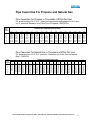
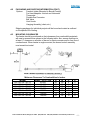
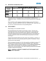
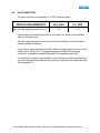
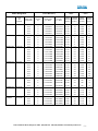
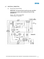
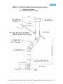
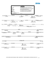
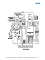
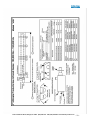
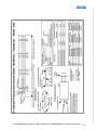
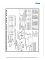
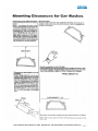
-INDEXA. INSTALLATION INSTRUCTIONS
1. TECHNICAL DATA
2
2–4
(a) General Information
(b) ER-Series heating Models (or GX, CW, AL, SC)
(c) Typical Arrangement of Heater
2. PACKAGING AND SHIPPING
4–5
3. MOUNTING CLEARANCES
5–6
4. PRE-ASSEMBLY
6
5. INSTALLATION
7
6. GAS CONNECTION
8–9
7. ELECTRICAL CONNECTION
10 – 11
8. VENT REQUIREMENT AND DETAILS
(a) Unvented units
(b) Vertical Vent
(c) Horizontal Vent
12 – 13
9. FRESH AIR DUCTED INTAKE
(a) Vertical Thru Roof
(b) Horizontal Thru Wall
10. INSTALLATION CHECK OUT AND START UP
B. SERVICE AND MAINTENANCE INSTRUCTIONS
1. Servicing Instructions
2. Routing Service
3. Replacement of Components
4. User Instructions
13
14 – 15
16 – 21
C. Appendix ‘A’
22-53
D. Appendix ‘B’
54-56
Note: All reference to standard specifications, codes, regulations, etc., are intended to
reflect latest editions included in the ANSI Testing, Construction, Performance and
Installation Standards. (ANSI/ NFPA standard 1985)
2319 Laurelbrook Street, Raleigh, NC 27604 · (800) 542-7221 · FAX (919) 834-4526 · www.ultimate-products.com
-1-
WARNING: Improper installation,
adjustment, alteration, service or
maintenance can cause property
damager, injury, or death. Read the
installation, operating, and maintenance
instructions thoroughly before installing or
servicing this equipment.
A. INSTALLATION INSTRUCTIONS
A.1
TECHNICAL DATA
(a) General Information
Model & Heat Input
Information all units:
Gas Supply Connection: ½-inch NPT Male
Electrical Supply: 120V, 1 phase, 60Hz
Current Rating: 1.2 AMP MAX (Burner-0.3/Fan –
0.9)
Ignition: Electronic Program Start-up with
Spark Ignition
OPTIONS:
1. Modify combustion chamber air intake for fresh air duct.
2. Ultimate Products Black Bulb Thermostat.
3. Control Panel with multi-zone capabilities. (Not A.G.A. Certified)
4. Individual Heater Vent to Exterior.
Notes:
A. Heater is intended for heating non-residential indoor and outdoor spaces and
should only be installed where flammable gases or vapors are not generally
present.
B. Indoor heaters may be suspended either horizontal or at an angle, or may be wall
mounted. Outdoor heaters must be suspended horizontally. SEE SECTION A.3
FOR CLEARANCES.
C. Installation shall conform with local building code requirements and with National
Fuel code ANSI-Z223.1.A. (Latest Edition) and section 7.8A-3; Z223.1 (Latest
Edition).
D. The unit shall be electrically grounded in accordance with National Electric Code
ANSI/NFPA 70-1987.
E. The heater may be installed in aircraft hangars when conformation with
ANSI/NFPA 409-1985 for Aircraft Hangars and in automotive garages when
conforming with ANSI-NFPA 88A (Latest Edition) for Parking Structures and
ANSI/NFPA 88B (Latest Edition) for Repair Garages.
Insure that minimum clearance will be maintained to vehicles parked below
the heater.
2319 Laurelbrook Street, Raleigh, NC 27604 · (800) 542-7221 · FAX (919) 834-4526 · www.ultimate-products.com
-2-
Pipe Capacities For Propane and Natural Gas
Pipe Capacities For Propane in Thousands of BTUs Per Hour
For pressure drop of 0.5” W.C., based on low-pressure piping based on 6 oz. per
sq. in. pressure. Based on one Cubic Foot of Propane = 2500 BTUs.
SIZE
PIPE
INCHES
½
¾
1
1¼
1½
2
3
4
LENGTH OF STRAIGHT PIPE IN FEET
15
105
425
787.5
1542.5
2425
5040
13545
28035
30
77.5
300
615
1070
1700
3490
9607.5
19687.5
45
65
245
505
882.5
1402.5
2835
7875
16222.5
60
55
212.5
440
770
1212.5
2520
6772.5
14017.5
75
50
190
395
677.5
1070
2205
5985
12600
90
45
172.5
362.5
630
977.5
2047.5
5512.5
11497.5
105
40
160
330
582.5
912.5
1890
5197.5
10710
120
150
180
210
240
270
300
450
600
150
315
542.5
857.5
1732.5
4882.5
9922.5
137.5
282.5
487.5
772.5
1575
4252.5
8820
125
252.5
440
700
1417.5
3937.5
8032.5
115
237.5
410
645
1322.5
3622.5
7560
107.5
220
385
607.5
1245
3387.5
6930
102.5
205
362.5
575
1165
3232.5
6615
95
197.5
347.5
542.5
1117.5
3072.5
6300
80
157.5
282.5
440
897.5
2520
5040
67.5
137.5
237.5
377.5
770
2127.5
4410
Pipe Capacities For Natural Gas In Thousands of BTUs Per Hour
For pressure drop of 0.5” W.C. pressure. Based on one Cubic Foot on Natural
Gas = 100 BTUs.
SIZE
PIPE
INCHES
½
¾
1
1¼
1½
2
2½
3
3½
4
LENGTH OF STRAIGHT PIPE IN FEET
10
20
30
40
50
60
70
80
90
100
125
150
175
200
300
400
500
600
700
800
1000
170
360
540
1125
1700
3100
5040
9100
118
245
440
790
1200
2225
3525
6500
9500
95
198
325
660
1000
1855
3000
5300
7880
80
169
285
570
865
1600
2600
4600
6780
9450
71
150
250
510
780
1450
2350
4435
6140
8500
64
135
225
465
720
1375
2175
3780
5670
7880
60
123
215
440
670
1250
2025
3530
5280
7325
55
115
195
410
620
1175
1890
3290
4940
6870
52
108
185
390
600
1120
1810
3140
4685
6550
49
102
177
375
570
1075
1745
3020
4300
6300
44
92
155
355
510
970
1570
2905
4000
5600
40
83
140
305
455
880
1420
2840
3660
5125
37
77
130
280
430
820
1315
2450
3380
4760
34
71
120
260
400
760
1225
2140
3185
4400
27
57
100
205
315
610
995
1640
2500
3145
23
48
80
180
265
530
845
1385
2300
3010
21
43
70
165
240
470
740
1210
1890
2870
19
39
65
140
215
420
660
1085
1690
2670
57
125
195
390
620
930
1545
2400
48
115
180
365
570
900
1445
2100
40
100
150
320
500
760
1245
1800
2319 Laurelbrook Street, Raleigh, NC 27604 · (800) 542-7221 · FAX (919) 834-4526 · www.ultimate-products.com
-3-
A.2
PACKAGING AND SHIPPING INFORMATION
See Appendix ‘A’ for assembly drawings. Materials lists with part numbers and
descriptions for each part will accompany each shipment.
Heaters include:
Burner/Control
Radiant Tubes
Reflectors
Brackets
Vacuum Fan
U-Bend (U-Tube Units only)
Wiring Junction Boxes (Straight Tube Units Only)
2319 Laurelbrook Street, Raleigh, NC 27604 · (800) 542-7221 · FAX (919) 834-4526 · www.ultimate-products.com
-4-
A.2
PACKAGING AND SHIPPING INFORMATION (CONT.)
Options:
Fresh air Intake (Mounted to Burner/Control)
Fan Vent Adapters- Vertical and Horizontal
Thermostat
Flexible Gas Connector
Ball Valve
Vent Hoods
Hanging Assembly (chain, etc.)
Shipping packages for individual projects will be boxed and crated as outlined
on the specific bill of lading.
A.3
MOUNTING CLEARANCES
The heater should be positioned so that clearances from combustible materials
will meet or exceed those shown in the following table. Also, ensure that there is
at least 6” clearance on all sides of burner for service access and for free flow of
combustion air. When heater is angle mounted, the burner/control assembly
must remain horizontal.
Minimum Clearances To Combustibles In Inches
Model
Input – BTU / HR
A
B
D
E
GH / ER / AL / SC 12
GH / ER / AL / SC 15
GH / ER / AL / SC 18
GH / ER / AL / SC 22
GH / ER / AL / SC 29
GH / ER / AL / SC 38
GH / ER / AL / SC 44
40,000
50,000
60,000
75,000
100,000
130,000
150,000
43
66
66
66
72
72
93
20
20
20
20
30
30
36
4
*
*
*
12
12
12
6
6
6
6
6
6
6
2319 Laurelbrook Street, Raleigh, NC 27604 · (800) 542-7221 · FAX (919) 834-4526 · www.ultimate-products.com
-5-
A.3
MOUNTING CLEARANCES (CONT.)
MOUNTING HEIGHT ABOVE FLOOR
Mounting
Position
Horizontal
Recommended
Minimum
Inclined
Recommended
Minimum
40,000 – 75,000 B.T.U
100,000 – 130,000 B. T. U.
150,000 B. T. U
14 ft
12ft
16ft
14ft
18ft
16ft
11ft
10ft
13ft
12ft
15ft
14ft
Ensure that there is adequate provision in the building for combustion and
ventilating air supply. Installation must meet minimum requirements of applicable
codes.
When installed in public garages and airplane hangars ensure that minimum
clearances specified in ANSI/NFPA 88A or B, ANSI/NFPA 409, respectively, are
met; and in no case less than those in the preceding tables.
A.4
PRE-ASSEMBLY
Each heating unit is assembled as follows:
Note that the emitter tube consists of more than one tube. The tube to be
connected to the burner box is the thinner stainless steel or aluminized steel
tube. Other tubes may be mild (thicker tubes), stainless or aluminized steel.
Connections between tubes is by a coupling with three bolts. The coupling has
an inner compression sleeve that holds the pipe securely when the nuts are
turned tight.
Support the assembled radiant tube with screws facing upwards, on blocks, etc.
at least 6” above floor level, preferably under the position of installation. Ensure
that the tube is clear internally.
Slip the suspension brackets onto the tube assembly and attach by means of “U”
bolts and nuts. Note that there are two types of brackets; type C and type B.
Type C attaches reflectors together. Bracket C & B are placed on the assembled
radiant tube in position shown on the assembly drawing in APPENDIX “A”.
Tighten nuts to secure brackets to the tubes at spacing indicated with all brackets
oriented in the same level position.
NOTE: CLOSE ALL S-HOOKS TO INSURE THAT THE CHAINS DO NOT
COME OFF OF THE HOOK.
2319 Laurelbrook Street, Raleigh, NC 27604 · (800) 542-7221 · FAX (919) 834-4526 · www.ultimate-products.com
-6-
A.5
INSTALLATION
Heater units: At this point raise the tube assembly into position and suspend from
previously fixed chains (9 gauge min. galvanized welded link construction), or
attach to wall mounting brackets. Wall mounting brackets must support heater at
an angle of inclination of 45° ±10°. Longer tube assembly may be raised in more
than one sub-assembly with final tube connection made in the air.
It is recommended that the heater be suspended to slope slightly downward from
the burner approximately 1 inch in 20 feet, but not more than 2 -inches total.
Remove the protective plastic film from the reflector surface. Note that each
section of reflector has two holes punched at one end. This end is firmly fixed by
bolting to the lugs provided on the reflector bracket type C. The other end of each
reflector section is free floating in suspension bracket type B thereby allowing for
thermal expansion.
Position reflector sections so that ends with holes lap at type C brackets and
secure with nuts, bolts, and large washers provided in the burner box crate.
Reflector should be allowed free movement through brackets type B. Note:
Reflectors may be installed before tube is raised to position at installer’s option.
Slide burner/control assembly onto the burner end of the radiant tube ensuring it
is fully engaged and upright, (i.e. with air inlet cover plate facing upwards) and
secure with locking screws provided.
Slide the fan assembly on the opposite end of radiant tube, ensuring that it is fully
engaged with fan outlet facing horizontally for outdoor installations and for indoor
installations either unvented or with horizontal thru wall venting. Fan outlet should
face upward for vertical venting thru the roof.
2319 Laurelbrook Street, Raleigh, NC 27604 · (800) 542-7221 · FAX (919) 834-4526 · www.ultimate-products.com
-7-
A.6
GAS CONNECTION
The gas connection on the heater is ½” NPT external thread.
SERVICE REQUIREMENTS
NAT. GAS
L.P. GAS
Max. inlet gas supply pressure (in.w.c.)
Min. inlet gas supply pressure (in.w.c.)
10.0
6.5
14.0
11.0
Injector sizes and manifold pressure for the burner are shown in the attached
table for all heater units.
The gas supply piping and connections must be installed so that the minimum
pressure stated is achieved.
A gas shut-off valve and union should be fitted in the gas supply line close to the
heater, and a 1/8 inch N.P.T. plugged tapping, accessible for test gauge
connection, provided immediately upstream of the appliance gas inlet.
It is essential to provide some flexibility in the final gas connection preferably by
use of an approved armored flexible connector or stainless steel expansion loop.
(See Appendix ‘A’)
2319 Laurelbrook Street, Raleigh, NC 27604 · (800) 542-7221 · FAX (919) 834-4526 · www.ultimate-products.com
-8-
Air Inlets
(Inches/ Millimeters)
Model Designation
GH/ER/AL/SC
GH/ER/AL/SC
GH/ER/AL/SC
GH/ER/AL/SC
GH/ER/l/SC
Model Tube
Configuration
Tube Dia.
(In)
Burner Intake
(in. / M.M.)
12/40,000
S-20
3"
S-25
3"
S-30
15/150000
18/60,000
22/75,000
29/100,000
GH/ER/AL/SC
SC/ER/GX
Input
KW
BTU/HR
38/130,000
44/150,000
Natural Gas
Orifice
Liquid Petroleum
Orifice
Fan Inlet
(in. / M.M.)
Injector
Diameter
(inches )
Manifold
Pressure
(in.W.C.)
Injector
Diameter
(inches)
Manifold
Pressure
(in./mm)
1.125"/29mm
1.312"/33mm
0.130"
1.9
0.080"
6.7
1.125"/29mm
1.438" /37mm
0.130"
1.9
0.080"
6.7
3"
1.125"/29mm
1.438" /37mm
0.130"
1.9
0.080"
6.7
U-20
3"
1.125"/29mm
1.187/30mm
0.130"
1.9
0.080"
6.7
U-30
3"
1.125"/29mm
1.187/30mm
0.130"
1.9
0.080"
6.7
S-20
3"
1.312"/33MM
1.438"/37 MM
0.130"
3
0.080"
6.7
S-25
3"
1.125"/29 MM
1.438"/37 MM
0.130"
3
0.080"
6.7
S-30
3"
1.125"/29 MM
1.438"/37 MM
0.130"
3
0.080"
6.7
U-20
3"
1.312"/33MM
1.438"/37 MM
0.130"
3
0.080"
6.7
U-30
3"
1.312"/33MM
1.312"/33 MM
0.130"
3
0.080"
6.7
S-20
3"
1.750"/44 MM
2.00"/50 MM
0.161"
2.4
0.098"
6.7
S-25
3"
1.312"/33 MM
1.438"/37 MM
0.161"
2.4
0.098"
6.7
S-30
3"
1.312"/ 33 MM
1.438"/37 MM
0.161"
2.4
0.098"
6.7
S-40
3"
1.312" /33 MM
1.438"/37 MM
0.161"
2.4
0.098"
6.7
S-20
3"
1.312" /33 MM
1.750"/44MM
0.161"
2.4
0.098"
6.7
S-30
3"
1.312" /33 MM
1.438"/37 MM
0.161"
2.4
0.098"
6.7
S-40
3"
1.312" /33 MM
1.312"/33MM
0.161"
2.4
0.098"
6.7
S-20
3"
1.750"/44 MM
2.625"/67 MM
0.161"
3.8
0.098"
10.5
S-25
3"
1.750"/44 MM
2.00"/50 MM
0.161"
3.8
0.098"
10.5
S-30
3"
1.750"/44 MM
2.00/50 MM
0.161"
3.8
0.098"
10.5
S-40
3"
1.750"/44 MM
1.75"/44MM
0.161"
3.8
0.098"
10.5
U-20
3"
1.750"/44 MM
2.625"/67 MM
0.161"
3.8
0.098"
10.5
U-30
3"
1.750"/44 MM
2.00/50 MM
0.161"
3.8
0.098"
10.5
U-40
3"
1.750"/44 MM
2.00/50 MM
0.161"
3.8
0.098"
10.5
S-40
4"
2.312"/59 MM
2.00"/50 MM
0.182"
4.9
1.20"
10
S-50
4"
2.312"/59 MM
2.00"/50 MM
0.182"
4.9
1.20"
10
S-60
4"
2.312"/59 MM
2.00"/50 MM
0.182"
4.9
1.20"
10
U-35
4"
2.312"/59 MM
2.00"/50 MM
0.182"
4.9
1.20"
10
S-40
4"
2.312"/59 MM
2.625"/67MM
0.206"
4.9
0.136"
10
S-50
4"
2.312"/59 MM
2.625"/67MM
0.206"
4.9
0.136"
10
S-60
4"
2.312"/59 MM
2.625"/67MM
0.206"
4.9
0.136"
10
U-35
4"
2.312"/59 MM
2.625"/67MM
0.206"
4.9
0.136"
10
S-40
4"
2.312"/59 MM
4.00"/100MM
0.228"
4.6
0.149"
10
S-50
4"
2.312"/59 MM
4.00"/100MM
0.228
4.6
0.149"
10
S-60
U-35
4"
4"
2.312"/59 MM
2.312"/59 MM
4.00"/100MM
4.00"/100MM
0.228
0.228
4.6
4.6
0.149"
0.149"
10
10
2319 Laurelbrook Street, Raleigh, NC 27604 · (800) 542-7221 · FAX (919) 834-4526 · www.ultimate-products.com
-9-
A. 7
ELECTRICAL CONNECTION
(a)
Burner/Control Internal Wiring
IMPORTANT: All electrical work should be done by a qualified
electrician in accordance with the National Electrical Code
ANSI/NFPA 70.
Supply: 120 V, 60 Hz, single phase
Current Rating: 0.3 amp max
2319 Laurelbrook Street, Raleigh, NC 27604 · (800) 542-7221 · FAX (919) 834-4526 · www.ultimate-products.com
- 10 -
A. 7
ELECTRICAL CONNECTION (CONT.)
The electrical supply to the heater is by three wires: live, neutral and ground
connections. It is recommended that the supply cable be in metallic conduit to
the 3/4'” hole provided.
Power is ONLY supplied to the terminal in the back of burner as shown below:
Power is supplied to fan through the knock out on the side of the burner housing.
Fan leads should be connected to the burner leads using the wire nuts provided.
Connect yellow/green wire from fan, to green wire of the burner, connect either
black wire from the fan, one to the white and one to the black/brown of burner.
Insure that conduit clamp is firmly tightened.
It is recommended that the electrical circuit controlling the heater or group of
heaters include thermostats, a time switch and if required manual control
switches. All such controls and switch gear must be rated to handle the total
inductive load of the circuit they control. For large installations, the use of relays
or contractors should be considered.
Control panels are available from the manufacturer incorporating multiple Black
Bulb Thermostats controlling up to 10 heaters per thermostat for zone control of
the heated area. Typical External Wiring is shown in diagram. (Control panels are
not A.G.A. design certified.)
2319 Laurelbrook Street, Raleigh, NC 27604 · (800) 542-7221 · FAX (919) 834-4526 · www.ultimate-products.com
- 11 -
A. 8
VENT REQUIREMENTS AND DETAILS
(1) UNVENTED UNITS: Heaters may be installed without a flue providing the
governing building codes are met and that consideration is properly given to
possibilities of condensation on cold surfaces.
Installation shall meet the following requirements when unvented:
(A) Internal volume of the heated room must be greater than 214 cu. ft. per
100 BTU/HR of heaters installed.
(B) Natural or mechanical means shall be provided to supply and exhaust at
least 4 CFM per 1,000 BTU per hour input of installed heaters.
(C) Combustion gases shall not impinge on combustible materials with a
temperature in excess of 150° F.
(D) The blower discharge must be horizontal.
(2) VERTICAL VENTING: The heater may be installed with a vertical flue. A
down vent elbow must be fitted to the induced draft fan exhaust outlet, which
should be rotated to a vertical position.
A vent elbow designed to accept a 6 -inch nominal sheet metal flue pipe is
available as an optional extra.
All flue piping should be adequately supported from the building structure and
terminated with an approved terminal. The maximum flue length is 30 ft. with
a maximum of two bends. All connections should be properly sealed.
Generally, terminal may be located horizontally a dimension equal to its
vertical dimension.
(3) HORIZONTAL VENTING: Individual units may be vented horizontally
through side walls. Venting must be installed in accordance with ANSI
Z2223.1 (NFPA-54) and local codes.
Maximum length of vent is 25 ft. with 2-90 degree long radius elbows.
Runs of 12 ft. or shorter can use 4-inch diameter flue with Ultimate Products
part number V0200.
Runs over 12 ft. should use 6-inch dia. flue pipe. Any portion of flue that
passes through a combustible wall must be insulated or use an approved
insulating thimble.
Recommended parts are Ultimate Products’ (Part # V-0200) for 4-inch flue
and (Part # V-0800) for 6-inch flue. Standard vent terminals must extend at
least 6-inches from the wall and at least 24-inches from any combustible
overhang. Protect the building material from degradation by flue gases.
2319 Laurelbrook Street, Raleigh, NC 27604 · (800) 542-7221 · FAX (919) 834-4526 · www.ultimate-products.com
- 12 -
A. 8
VENT REQUIREMENTS AND DETAILS (CONT.)
Flue joints should be sealed using RTV high temperature sealant and secured
using at least three (3) sheet metal screws. Should condensation occur flue
should be shortened or insulated.
The terminal must exit the building at least 7 ft. above any area accessible to
the public.
The terminal must be at least 3ft. away from any air intake to the building.
If the heater is equipped with ducted combustion air, the terminal must be at
least 3 ft. away from the air inlet and located higher than the inlet.
The vent terminal must be protected from blockage by snow.
A.9
FRESH AIR DUCTED INTAKE
Whenever the heater is installed in locations where air born dust or other polluted
atmosphere is present; a fresh air supply should be ducted to the burner.
A heater modified for fresh air intake should be specified when ordering. This
model is modified with a 4 -inch diameter duct connection at the burner.
A fresh air duct of 4-inch diameter should be installed from the fresh air to the air
intake connection on the burner housing. A flexible jointing piece should be
installed at the burner connection with hose clamps to facilitate the disconnection
when servicing the burner assembly.
The maximum recommended length of fresh air duct is 25 feet and the
maximum number of bends is two (2). The minimum length is 18 inches. The
location of the fresh air duct inlet must be where it will receive dust free clean air.
An Ultimate Products inlet cap with bird screen must be fitted at the inlet of the
duct. If the duct inlet is located above the roof the underside of the inlet terminal
must be at least 2 ft. above roof level and at least 10 inches above any projection
on the roof within 7 ft. of the inlet.
See Appendix ‘A’ for typical installation drawing and Ultimate Products part
numbers. Intake pipe, fittings, and sealant are not furnished by Manufacturer.
2319 Laurelbrook Street, Raleigh, NC 27604 · (800) 542-7221 · FAX (919) 834-4526 · www.ultimate-products.com
- 13 -
A.10 INSTALLATION CHECK OUT AND START UP
Inspect installation and ensure that it has been carried out in accordance with
these instructions. Ensure that electrical and gas supplies are isolated.
The gas supply should be purged and tested for soundness in accordance with
Local and National Safety codes.
Open isolating gas valve and test gas connections for soundness using soap
solution.
Remove burner cover plate by unscrewing 6 screws. Take care not to damage
the sealing gasket. Inspect the burner and electrode assemblies ensuring these
are securely fixed and all electrical connections securely made. Replace the
burner cover plate ensuring that the sealing gasket is correctly positioned and the
six screws are fully tightened. The heater will not operate until this plate is
refitted.
Remove the control housing cover plate by unscrewing the five securing screws.
Ensure all internal components are securely fixed and all connections securely
made. Open the manual gas valve.
Switch on the electrical supply to the heater and observe the correct start up
sequence. Ensure that the settings of any time switch and thermostat are such
that the heating system will be required to operate.
The fan will start to run and “Power On” lamp will illuminate. Safe-start checks
are carried out automatically.
After the fan has run up to full speed and a satisfactory vacuum condition has
been established, ignition sequence will commence. The spark ignition will be
energized producing a spark at the ignition electrode. The gas valve will at the
same time be energized.
If the ignition is successful the flame sensing probe and the ignition spark is
switched off. The ‘burner on” lamp indicates that the gas solenoid valve is
energized.
If ignition is unsuccessful the gas valve will close and the spark ignition deenergized after approximately 6 seconds. For approximately 10 to 20 seconds
the fan will purge the system then re-ignition will be attempted. After three (3)
attempts at ignition the control unit will “lock-out” - the “power on” lamp will
remain illuminated and the fan will continue to run. To reset after “lock-out” switch
off the power supply to the system and wait 5 minutes. Then turn the power on.
If repeated “locked-out” occurs investigate the cause.
2319 Laurelbrook Street, Raleigh, NC 27604 · (800) 542-7221 · FAX (919) 834-4526 · www.ultimate-products.com
- 14 -
A.10 INSTALLATION CHECK OUT AND START UP (CONT.)
To shut down the heater, switch off the power supply to the system. Automatic
control of the heater or a series of heaters may be achieved by incorporating
thermostats, time switches, manual over-ride switches etc. in the electrical supply
to the heater(s). It is essential to allow a delay of 15 seconds after switching off
the system before attempting to restart.
If at a ny time after completion of the start up sequence, loss of flame should
occur, the control unit will attempt to reignite. If this is unsuccessful lock out will
occur.
Set burner gas pressure as follows. Switch off the power supply to the heating
system. Connect a ‘U’ tube manometer to the pressure test nipple provided on
the combination gas control valve. Remove the cover from the pressure regulator
revealing the adjustable screw. Start the heater and using a suitable screwdriver
adjust the pressure regulator, turning the screw clockwise to increase the
pressure or counter clockwise to decrease the pressure. Set the pressure to
appropriate in w.c. from the table of dimensions for correct heater description.
Switch off the power supply to the heating system. Disconnect ‘U’ tube
manometer and securely replace screw in pressure test nipple. Replace cover
screw on pressure regulator.
Check the operation of the flame safeguard equipment as follows: With the
heater running normally, switch off the gas supply at the shut off valve. The
heater should attempt to relight and if the gas valve has been left off “lockout”
should occur indicated by the “Power On” light only being illuminated and fan
running.
Check the operation of the vacuum proving switch as follo ws. With the heater
running normally, pull off the silicone rubber tube connecting the vacuum switch
to the combustion chamber. Within one second, the burner should shut off. Then
replace the tube securely and observe that the heater proceeds to ignite in the
normal way.
Replace the controls cover securing the five fixing screws.
2319 Laurelbrook Street, Raleigh, NC 27604 · (800) 542-7221 · FAX (919) 834-4526 · www.ultimate-products.com
- 15 -
B. SERVICE AND MAINTENANCE
INSTRUCTIONS
B.1
SERVICING INSTRUCTIONS
Under normal working conditions, it is recommended that the Ultimate Products
Heater should be serviced annually. In exceptionally dirty or dusty conditions
such as may occur in a foundry, more frequent servicing may be desirable.
Servicing work should be carried out by a qualified gas service engineer.
IMPORTANT:
1.
Never rest anything, especially ladders, against the heater.
2.
Turn off gas and electrical supplies before servicing or repair work is
started.
3.
Unless otherwise instructed, reassemble parts in reverse order to the
following instructions.
B.2
ROUTINE SERVICE
A. FAN – Inspect the main fan propeller and remove any dust brushing with a
soft brush. Similarly remove any dust from the finger guard covering the
secondary (cooling) impeller and the mesh aperture in the motor cover. Ensure
that the impeller turns
freely and that there is not excessive play in the bearings.
B. EMITTER TUBE – Brush away any dust on the exterior of the emitter tube.
Inspect the emitter tube internally by removing the burner control box as directed
in “D” below. If there is any appreciable build up of dust or deposits, the tube
should be cleaned internally. The emitter tube may be cleaned by use of an
industrial vacuum cleaner with a long extension tube, which is passed down the
emitter tube.
Replace the burner/control assemblies engaging them fully on their tubes and
secure by tightening the screws ensuring that they are squarely positioned (i.e.
with the air inlet cover plate facing upwards).
C. REFLECTOR – The condition of the reflector should be noted and any
necessary cleaning performed. The reflectors can be simply removed for
cleaning by removing the reflector clamp screws securing them to the
suspension brackets and sliding them out of the suspension brackets. The
reflector can be cleaned with a soft cloth and detergent in water.
A mild non-abrasive metal polish may be used in cases of extreme discoloration.
D. REMOVAL OF BURNER/CONTROL ASSEMBLY – Remove the burner/
control assembly by disconnecting the gas and electrical supply (and fresh air
inlet duct if fitted). Slacken the burner fixing screws and draw the assembly off
the emitter tube.
2319 Laurelbrook Street, Raleigh, NC 27604 · (800) 542-7221 · FAX (919) 834-4526 · www.ultimate-products.com
- 16 -
E. BURNER NER/ELECTRODE ASSEMBLY – Inspect the burner/electrode
assembly by removing the six screws securing the combustion chamber cover
plate to top of
control box, taking care not to damage the sealing gasket.
Remove the burner head by unscrewing it from the injector taking care not to
drop it on the leads of the ignition electrodes. Replace the electrode assembly if it
is not in good condition. The assembly is removed by removing the screws which
attach it to the bracket on the front wall of the combustion chamber. The
assembly is then lifted out of the combustion chamber and the cable
disconnected. If the electrode assembly is in good order check the spark
electrode gap, this should be .125 inches ±.030 inches. Adjust the gap if
necessary by bending the ground rod. Ensure the electrical connections are
secure.
Inspect the injector a nd clean as necessary using a soft bristle brush. To remove
or replace the injector, with the burner head removed, unscrew the injector from
its carrier using a wrench, on the hexagon portion of its body. When replacing the
injector ensure that it is fully tightened in its carrier. (TIGHTEN SNUG -- DO NOT
OVERTIGHTEN)
Replace the burner head. Replace the combustion chamber top cover, renewing
the rubber sealing gasket if this is not in good condition.
Inspect the burner fresh air inlet duct if fitted and ensure that it is free of any
blockage or obstruction. Inspect the air inlet terminal and ensure this is not
liable to obstruction.
Recheck the heater by following the procedure for check out and start up,
taking care to check that the burner gas pressure is correctly set, and that the
vacuum switch and flame safeguard equipment function correctly.
F. AUXILIARY CONTROLS – Check that auxiliary controls such as room
thermostats, time switches, etc. function correctly and are set to operate at the
desired temperatures. Ensure that the user is aware of the functions of the
auxiliary controls and their correct settings. For most efficient operation of the
heating system the time switch, if fitted, should be set to switch on normally
between ¼ hour and 1 hour before commencement of occupancy of the building
depending on local conditions. The correct setting of the room thermostat can
only be determined by experience in cold weather when it should be set to shut
off the heaters when a comfortable level of warmth has been achieved. This
setting will normally be several degrees below that which would be required with
a convective heating system.
2319 Laurelbrook Street, Raleigh, NC 27604 · (800) 542-7221 · FAX (919) 834-4526 · www.ultimate-products.com
- 17 -
B. 3
REPLACEMENT OF COMPONENTS
WARNING: TURN OFF GAS AND ELECTRICAL SUPPLIES
BEFORE STARTING REPAIR WORK.
A. TO REPLACE ANY COMPONENTS IN THE BURNER/CONTROL
ASSEMBLY – This assembly should be removed from the heater by
disconnecting the gas and electrical supplies (also the fresh air intake
duct if used). Loosen the bolts and slide the burner/control assembly
from the emitter tube.
B. TO REPLACE ELECTRODE ASSEMBLY – Remove top cover of
combustion chamber by removing six (6) screws. Remove the screws
securing the electrode assembly and pull off the electrode cable
connector. Reconnect the cable connector to the new electrode
assembly and replace the assembly. Replace the cover plate and
gasket. Spark electrode gap .125 ±.030”.
C. TO REPLACE THE BURNER HEAD – Remove combustion chamber
cover as in section B above. Unscrew burner head from injector. Screw
on new burner head. Replace combustion chamber cover.
D. TO REPLACE THE INJECTOR – SEE PAGE 17
E. TO REPLACE COMBINATION GAS VALVE – Remove combustion
chamber cover as in paragraph B. Remove control housing cover.
Remove burner head as in paragraph C. Unscrew the gas supply pipe
entering the combination gas valve. Remove the electrical connections
from the valve. Remove the two (2) screws holding the gas valve. The
combination gas valve can now be removed.
Replace any defective component and reassemble using approved
pipe joining compound on pipe threads.
2319 Laurelbrook Street, Raleigh, NC 27604 · (800) 542-7221 · FAX (919) 834-4526 · www.ultimate-products.com
- 18 -
F. TO REPLACE THE BURNER/CONTROL UNIT – Remove the control
housing cover. After observing their positions, disconnect the wires to
the burner control unit. Remove the screws securing the burner control
unit to the base of the control housing. Remove the burner control unit.
Install replacement unit, observing correct positions for color coded
cables.
G. TO REPLACE THE VACUUM SWITCH – Remove the burner control
unit as in paragraph F. Disconnect the rubber tube connection at the
vacuum switch. Disconnect push on connectors from the vacuum
switch. Remove the screws securing the vacuum switch and slip the
switch out of its bracket. Installing is the reversal of the above taking
care to correctly reconnect the cables.
H. TO REPLACE THE RELAY - Remove control housing cover. The
relay is a plug-in type and can be changed without removing any other
components. However, if necessary, remove the burner control unit to
gain better access to the relay.
B. 4
USERS INSTRUCTIONS
Hand the Users Instruction to the user and explain how to operate the heater.
Leave the Installation and Servicing Instructions with the service maintenance
engineer or manager for use on future service calls.
2319 Laurelbrook Street, Raleigh, NC 27604 · (800) 542-7221 · FAX (919) 834-4526 · www.ultimate-products.com
- 19 -
USER INSTRUCTIONS
ULTIMATE PRODUCTS TUBULAR RADIANT HEATERS
Ultimate Products is the distributor of a series of tubular infrared heaters
designed for overhead heating of industrial and commercial buildings. Individual
heating units are suspended from the roof or mounted at an angle on the wall
when inside buildings or horizontal when outside.
IMPORTANT
1. This appliance must only be installed by qualified craftsman in accordance
with the requirements of local and national codes.
2. This appliance must be grounded in accordance with the National Electrical
code ANSI/NFPA No.70.
3. Never rest anything, especially ladders, against the heater.
TO START THE HEATER
1. First ensure that the gas supply to each heater is turned on by opening main
gas shut-off valve and manual valve on combination control.
2. Ensure that the settings of any time switch and thermostat are such that the
heating system will be required to operate.
3. Switch on the electrical supply to the heater. The fan will start, the “Power On”
light on the burner will illuminate and ignition will commence.
4. Ignition will occur and the burner light, colored orange, will illuminate.
5. If ignition is unsuccessful the gas valve will close and the spark igniter deenergize after approximately six (6) seconds. For approximately 10 to 20
seconds the fan will purge the system then re-ignition will be attempted. After
three (3) attempts at ignition the control unit will lockout, the “power-on” lamp
will remain illuminated and the fan will continue to run. To reset after
“lockout”, switch off the power supply to the heater and wait 5 minutes. Then
turn the power on. If repeated “lockout” occurs investigate the cause.
TO SWITCH OFF THE HEATER
Switch off the electrical supply. The burner will shut off and the fan will stop.
2319 Laurelbrook Street, Raleigh, NC 27604 · (800) 542-7221 · FAX (919) 834-4526 · www.ultimate-products.com
- 20 -
SERVICING
To ensure continued efficient and safe operation it is recommended that the
heater be serviced regularly by a qualified person, e.g. every year in normal
working conditions but in exceptionally dusty or polluted conditions more frequent
servicing may be needed.
2319 Laurelbrook Street, Raleigh, NC 27604 · (800) 542-7221 · FAX (919) 834-4526 · www.ultimate-products.com
- 21 -
Appendix A
2319 Laurelbrook Street, Raleigh, NC 27604 · (800) 542-7221 · FAX (919) 834-4526 · www.ultimate-products.com
- 22 -
2319 Laurelbrook Street, Raleigh, NC 27604 · (800) 542-7221 · FAX (919) 834-4526 · www.ultimate-products.com
- 23 -
2319 Laurelbrook Street, Raleigh, NC 27604 · (800) 542-7221 · FAX (919) 834-4526 · www.ultimate-products.com
- 24 -
2319 Laurelbrook Street, Raleigh, NC 27604 · (800) 542-7221 · FAX (919) 834-4526 · www.ultimate-products.com
- 25 -
LEGEND
0.25 BSSR
1.0 BTL
2BA RSE
0.187 BSSR
0.25 NIFR
5 NIFB
WIRE SPECS:
ALL ~ 18 A.W.G. UL 1015
WIRE LENGTH TOL:
0.25” INSULATED FEMALE RECEPTACLE
1.0mm2 NON-INSULATED BOOTLACE TERMINAL
2BA RED SHROUDED EYELET
0.187” INSULATED FEMALE RECEPTACLE
0.25” NON- INSULATED FLAG TERMINAL
5mm NON- INSULATED FEMALE BULLET
+10 / -0
2319 Laurelbrook Street, Raleigh, NC 27604 · (800) 542-7221 · FAX (919) 834-4526 · www.ultimate-products.com
- 26 -
2319 Laurelbrook Street, Raleigh, NC 27604 · (800) 542-7221 · FAX (919) 834-4526 · www.ultimate-products.com
- 27 -
2319 Laurelbrook Street, Raleigh, NC 27604 · (800) 542-7221 · FAX (919) 834-4526 · www.ultimate-products.com
- 28 -
Wiring Schematic
(Part #: S-0500A)
2319 Laurelbrook Street, Raleigh, NC 27604 · (800) 542-7221 · FAX (919) 834-4526 · www.ultimate-products.com
- 29 -
2319 Laurelbrook Street, Raleigh, NC 27604 · (800) 542-7221 · FAX (919) 834-4526 · www.ultimate-products.com
- 30 -
2319 Laurelbrook Street, Raleigh, NC 27604 · (800) 542-7221 · FAX (919) 834-4526 · www.ultimate-products.com
- 31 -
2319 Laurelbrook Street, Raleigh, NC 27604 · (800) 542-7221 · FAX (919) 834-4526 · www.ultimate-products.com
- 32 -
2319 Laurelbrook Street, Raleigh, NC 27604 · (800) 542-7221 · FAX (919) 834-4526 · www.ultimate-products.com
- 33 -
2319 Laurelbrook Street, Raleigh, NC 27604 · (800) 542-7221 · FAX (919) 834-4526 · www.ultimate-products.com
- 34 -
2319 Laurelbrook Street, Raleigh, NC 27604 · (800) 542-7221 · FAX (919) 834-4526 · www.ultimate-products.com
- 35 -
2319 Laurelbrook Street, Raleigh, NC 27604 · (800) 542-7221 · FAX (919) 834-4526 · www.ultimate-products.com
- 36 -
2319 Laurelbrook Street, Raleigh, NC 27604 · (800) 542-7221 · FAX (919) 834-4526 · www.ultimate-products.com
- 37 -
2319 Laurelbrook Street, Raleigh, NC 27604 · (800) 542-7221 · FAX (919) 834-4526 · www.ultimate-products.com
- 38 -
2319 Laurelbrook Street, Raleigh, NC 27604 · (800) 542-7221 · FAX (919) 834-4526 · www.ultimate-products.com
- 39 -
2319 Laurelbrook Street, Raleigh, NC 27604 · (800) 542-7221 · FAX (919) 834-4526 · www.ultimate-products.com
- 40 -
2319 Laurelbrook Street, Raleigh, NC 27604 · (800) 542-7221 · FAX (919) 834-4526 · www.ultimate-products.com
- 41 -
2319 Laurelbrook Street, Raleigh, NC 27604 · (800) 542-7221 · FAX (919) 834-4526 · www.ultimate-products.com
- 42 -
2319 Laurelbrook Street, Raleigh, NC 27604 · (800) 542-7221 · FAX (919) 834-4526 · www.ultimate-products.com
- 43 -
2319 Laurelbrook Street, Raleigh, NC 27604 · (800) 542-7221 · FAX (919) 834-4526 · www.ultimate-products.com
- 44 -
2319 Laurelbrook Street, Raleigh, NC 27604 · (800) 542-7221 · FAX (919) 834-4526 · www.ultimate-products.com
- 45 -
2319 Laurelbrook Street, Raleigh, NC 27604 · (800) 542-7221 · FAX (919) 834-4526 · www.ultimate-products.com
- 46 -
2319 Laurelbrook Street, Raleigh, NC 27604 · (800) 542-7221 · FAX (919) 834-4526 · www.ultimate-products.com
- 47 -
2319 Laurelbrook Street, Raleigh, NC 27604 · (800) 542-7221 · FAX (919) 834-4526 · www.ultimate-products.com
- 48 -
2319 Laurelbrook Street, Raleigh, NC 27604 · (800) 542-7221 · FAX (919) 834-4526 · www.ultimate-products.com
- 49 -
2319 Laurelbrook Street, Raleigh, NC 27604 · (800) 542-7221 · FAX (919) 834-4526 · www.ultimate-products.com
- 50 -
2319 Laurelbrook Street, Raleigh, NC 27604 · (800) 542-7221 · FAX (919) 834-4526 · www.ultimate-products.com
- 51 -
2319 Laurelbrook Street, Raleigh, NC 27604 · (800) 542-7221 · FAX (919) 834-4526 · www.ultimate-products.com
- 52 -
2319 Laurelbrook Street, Raleigh, NC 27604 · (800) 542-7221 · FAX (919) 834-4526 · www.ultimate-products.com
- 53 -
APPENDIX ‘B’
2319 Laurelbrook Street, Raleigh, NC 27604 · (800) 542-7221 · FAX (919) 834-4526 · www.ultimate-products.com
- 54 -
2319 Laurelbrook Street, Raleigh, NC 27604 · (800) 542-7221 · FAX (919) 834-4526 · www.ultimate-products.com
- 55 -
2319 Laurelbrook Street, Raleigh, NC 27604 · (800) 542-7221 · FAX (919) 834-4526 · www.ultimate-products.com
- 56 -
2319 Laurelbrook Street, Raleigh, NC 27604 · (800) 542-7221 · FAX (919) 834-4526 · www.ultimate-products.com
- 57 -