1
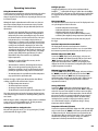
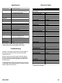
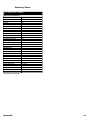
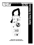
INSTRUCTION MANUAL
INF200
1-800-547-5740 • Fax: (503) 643-6322
www.ueitest.com • email: [email protected]
Introduction
International Symbols
The INF 10 0 / 200 non-contact infrared thermometer provides a faster,
easier way to take diagnostic temperature measurements. Monitor the
t e m p e rature of transformers, circuit breaker panels, motors and bearings,
supply and return registers, ducts, inlet/outlet steam lines, furnace flues
and many other surfaces. Use the INF 200 when diagnosing temperature
problems to save time and reduce the risk of burns and injuries.
Features include
• Switchable ˚F or ˚C readings
• Quick and simple operation
• Back-light
• Long battery life
• Temperature range of 0 to 788˚F (-20 to 420˚C)
• On-board nine measurement memory
• Barrel sight targeting
• Laser targeting
• User programmable alarm
Controls and Indicators
12
11
8
9
6
Safety Notes
Before using this instrument, read all safety information carefully. In
this manual the word "WARNING" is used to indicate conditions
or actions that may pose physical hazards to the user. The word
"CAUTION" is used to indicate conditions or actions that may
damage this instrument.
WARNING!
DO NOT point the laser toward the eyes or face of a person or animal.
Laser light can cause eye injury, if the beam makes direct eye contact.
Reflective laser light can also cause damage, if a mirror or a glass-like
surface reflects the beam directly into the eye. Laser’s potential to cause
damage is retained for hundreds of feet. Use caution.
CAUTION!
This equipment is intended for use be industry professionals who know
their professional environments. Temperature measurements are often
taken in potentially hazardous ares. Know and use the safety standards
prescribed by your profession.
4
5
7
1
2
3
10
1. Fahrenheit / Centigrade select push-button, and mode down /
decrease push-button.
2. Backlight push-button, and up / increase selector.
3. Temperature display mode select, memory recall and programming
select (INF200) push-button.
Validate Measurements
The accuracy and validity of measurements taken with this device
depends on various criteria. One of the most critical criteria to consider
is emissivity (a more detailed explanation is provided in the validation
section of this manual). Before using this instrument to determine if an
area is safe to touch, or enter, verify your readings are reasonably
accurate by using comparisons with already known measurements.
4. Temperature display mode indicator.
Laser Splash:
9. E m i s s i v i tyannunciator.
Indicates the use of laser equipment and the category of laser used.
10. Laser targeting on / off push-button.
5. Temperature measurement.
6. Fahrenheit / Centigrade scale indicator.
7. Low battery annunciator.
8. M e m o ry location annunciator.
11. Laser on annunciator.
12. Alarm mode indicator.
INF200-MAN
P. 1
Operating Instructions
Taking Measurement Samples
To take temperature measurements, point the instrument at the surface
to be measured and pull the trigger. A tube has been incorporated
along the top of the barrel to aid the user in spotting the surface area to
be measured (target).
Although this simple explanation works well in most cases, there are
other factors that may impact the measurement accuracy. Consider
there influences before using the data you obtain with your infrared
thermometer.
• The target must completely fill the spot diameter seen by the
infrared sensor, otherwise the temperature displayed will be
influenced by the surface surrounding the target. The ratio of
the distance from the end of the barrel to the size of the spot
being measured is 8:1. For example, using the INF200, an
object that is 6” in diameter can be accurately measured from
4’ away. When using the gun to find hot-spots, accuracy of the
reading is not as important as keeping the gun at the same
distance from the target for each sample measurement. If you
are looking for hot-spots on electrical panels, for instance, you
could take the readings from 6’ away each time, even though
you may only be filling half the spot diameter. The critical
information in this process would be any significantly
higher temperatures
• Emissivity of an object will also affect accuracy. See the
“Validation” section for details
• This instrument is sensitive to electromagnetic interference
(EMI), such as that generated by spark plug wires, radio
transmitters and welders. Do not use this instrument in close
proximity to equipment that may produce such interference
• The instrument must be used within the ambient temperature
range specified in the specification table
Each time the trigger is pulled your INF200 monitors four different
readings, regardless of the selected mode. They are:
•
•
•
•
The highest temperature measured
The lowest temperature measured
The average temperature (time weighted)
The Net difference between the light and low temperature “DT”
These four measurements go into the first memory location for future
recall, when the trigger is released. See “Recalling memory points” for
more details.
While the trigger is pulled, a temperature sample is taken at a minimum
of once every 1/2 second (500 milliseconds). The four parameters
mentioned above are updated at the same rate.
Selecting Fahrenheit or Centigrade Scales
Select the scale you prefer to use (˚F or ˚C) by pressing the (“˚F/˚C▼”)
push-button while the trigger is pulled.
INF200-MAN
Backlight Operation
To toggle the backlight on or off, press the push-button with the
backlight “
“ symbol while the trigger is pulled. Once the backlight
has been turned on, it will come on each time the trigger is pulled until
it is toggled off. Please note that this feature significantly reduces the
battery’s life.
Measurement Modes
This instrument allows you to select from one of five display modes. You
can cycle through the modes in this order:
•
•
•
•
•
Real-time temperature measurements
Maximum temperature measured (MAX mode)
Minimum temperature measured (MIN mode)
Temperature difference between MAX and MIN (∆T mode)
Calculated (time weighted) average temperature (AVG mode)
The last mode selected will remain selected the next time you pull
the trigger.
Real-time Temperature Measurement Mode
This display mode shows the actual temperature of surfaces
measured. This value is updated at least once ever 1/2 second. When
the instrument is powered up for the first time, this mode is pre-set.
Maximum Temperature (MAX) Mode
To enter the “MAX” display mode, pull the trigger, and press and
release the “MODE” push-button repeatedly until you see the word
“MAX” displayed on the LCD. In the “MAX” mode the highest
temperature measurement taken, during the current trigger pull, is
displayed on the LCD. The temperature reading will update each time
a higher temperature is measured.
Minimum Temperature (MIN) Mode
To enter the “MIN” display mode, pull the trigger, and press and release
the “MODE” push-button repeatedly until you see the word “MIN”
displayed on the LCD. In the “MIN” mode, the lowest temperature
measurement taken, during the current trigger pull, is displayed on the
LCD. The temperature reading will update each time a new lower
t e m p e rature is measured.
Average (AVG) Mode
To select the “AVG” display mode, pull the trigger and press and
release the “MODE” push-button repeatedly until “AVG” is displayed
on the LCD. The term “time weighted” in reference to the averaging
mode means all temperature measurements taken, from the time the
trigger was first pulled, are averaged while taking measurements in
this mode. If you were to walk along a wall for one minute taking
readings that were generally 72 degrees, then walk by a spot for
1/2 second that was 20 degrees, no significant change in average
temperature would be displayed.
Temperature Differential (∆T) Mode
To select the temperature differential display mode “∆T”, pull the trigger
and press and release the “MODE” push-button repeatedly until “∆T”
is displayed on the LCD. This display mode is used to determine the
net temperature difference between two surfaces. This is particularly
valuable when calculating net heating or cooling, since ambient
temperature is effectively removed from the equation.
P. 2
Validation
NOTE: Always validate your instrument’s accuracy each time it is put
into service.
The term validation, as we use it here, is the method used to verify the
measurement you are taking is accurate. Emissivity is a value, referring
to the surface you are targeting, that relates to that surface’s ability to
“emit” versus “reflect” heat energy. This value is a ratio of emitted heat
energy to the total heat energy available (example, .95 to 1). Because
the ratio is always referenced to a total available value of “1”, only the
emitted heat value, typically between .30 for surfaces that reflect most
of the available heat energy, to a high of around .98 for surfaces that
emit nearly all of their heat energy.
Some shiny, bright, polished or smooth surfaces reflect heat energy,
and therefore, don’t have high emissivity ratings. Generally these surfaces
are not recommended as targets for non-contact thermometers. They ca n ,
h owever, be prepared for non-contact measurement. Compensating for
e m i s s i v i tyof an object is part of the validating procedure. For frequently
repeated processes that warrant the use of a non-contact thermometer,
take the time to perform one of the following prepara t o ryprocedures:
• Pre-validate Accuracy: Most non-metallic surfaces have a
natural emissivity value of about .95 (this instrument’s factory
default), and need no additional preparation for measurement.
To validate, take sample temperature readings from a surface
in a controlled environment and compare them to the known
temperature. For example, measure an empty cardboard box
that has been sitting in a room for at least ten minutes, and
compare those readings to the known room temperature.
If a controlled environment is impractical, use contact
temperature measuring devices such as UEi’s DT series
thermometers or any one of the broad line of temperature
measurement products, used in conjunction with one of UEi’s
ATT series contact thermometer probes.
For a quick validation, compare the reading of a prepared test
area (see the next section ) to an unprepared area. If there is no
difference, there's no need for additional preparation.
• Physically Prepare Surfaces For Consistent Readings:
Some objects, such as lead and certain other alloys have low
e m i s s i v i tyratings. When temperature extremes and environmental
conditions allow, the surface of such material can be modified to
change the emissivity value to the conventional .95.
To prepare these surfaces to provide an accurate reading using
a non-contact thermometer, pre-treat (to emit energy) the
surface with flat colored paint, masking tape, or some similar
rough, dark, dull or porous coating that has an inherently high
emissivity value. Make sure these surfaces won’t experience
extreme environments that may burn, weather or otherwise
degrade the surface preparation.
Be sure not to harm the surface of the object you are preparing
for non-contact measurement. Often materials are designed
to be reflective to control heat build-up. Emissive surfaces
may cause excessive heat energy to be retained, even in a
small area, which may eventually damage the equipment or
impair operation.
Recalling Memory Points
With each pull of the trigger, four values are recorded in memory.
•
•
•
•
The highest temperature measured
The lowest temperature measured
The average temperature (time weighted)
The value last displayed before releasing the trigger
A total of nine sets of these four values, representing nine trigger pulls,
are available for recall. To review recorded values, start with the
instrument off, (trigger released and nothing visible on the LCD), then
press and release the “MODE” push-button. The number “1” will
appear on the display, indicating the latest of the nine sets of values
recorded in memory. You may now either cycle through each of the
four values recorded during the last trigger pull, or go to one of the four
values, then select the number of the trigger pull you wish to review.
For example, to select the high temperature measured three trigger pulls
ago, you may either:
1. Press the “MODE” push-button once. The number “1” and
a value appears.
2. Press the “
/▲“ push-button twice. The number “3” and
a value appears.
3. Press the “MODE” push-button once again. The word “MAX”
appears in the lower left of the LCD, along with the highest
temperature recorded three trigger pulls prior.
OR:
1. Press the “MODE” push-button once. The number “1” and
a value appears.
2. Press the “MODE” push-button once again. The word “MAX”
appears in the lower left of the LCD, along with the highest
temperature recorded during the last trigger pull.
3. Press the “
/▲“ push-button twice. The number “3” and
a value of the highest temperature recorded from three trigger
pulls ago appear.
To maneuver up and down through recorded values, press the
appropriate “˚F/˚C/▼” or “
/▲“ push-button to view the different
readings on the LCD.
Audible Alarms
The INF200 will sound an audible alarm at both an upper and a lower
temperature limit, whig you set.
To adjust the alarm, start with instrument’s power turned off. Press and
hold the “MODE” push-button until you hear an audible beep. Either
“MAX” or “MIN” will be displayed on the LCD, along with a value to
the right. Do not pull the trigger.
Select the mode “MAX” or “MIN” you want the instrument to provide
the alarm for by pressing either the “˚F/˚C/▼” push-button to select the
low temperature alarm or the “
/▲“ push-button to select the high
temperature alarm. Once the instrument indicates the alarm mode you
want to set, press the “MODE” push-button again.
Once the surface has been prepared, validate your readings as
previously indicated.
INF200-MAN
P. 3
You’re now ready to adjust the alarm’s threshold value, displayed on the
LCD. To decrease the value press the “˚F/˚C/▼” push-button. To
increase this value, press the “
/▲“ push-button. To lock this value
in, once again, press the “MODE” push-button again.
The alarm settings (whatever is displayed at the time) are instantly
saved if, at any time during the alarm setting process, the instrument
either shuts off after five seconds of inactivity or the trigger is pulled.
Emissivity Adjustment
When a process calls for repeated measurements of like materials,
such as evaluating a plastic’s solidity at a processing plant, the best
method of attaining quick, reliable temperature readings is to adjust
the emissivity setting of your INF200.
To set emissivity you must pass through the alarm setting function. As
described earlier, press and hold the “MODE” push-button until an
audible tone is heard, and the LCD displays the alarm adjustment
function. Do not pull the trigger, or let the instrument time-out and turn
off. Press the “MODE” push-button once more to display the current
emissivity value.
To decrease the value press the “˚F/˚C/▼” push-button. To increase the
value, press the “
/▲“ push-button.
To exit and save the newly set value, press the “MODE” push-button
again, let the instrument time-out in five seconds, or pull the trigger.
The value last entered for emissivity will become the instrument’s
default next time it is used. If the instrument will be used on various
surfaces or by various people for different applications, it is a good
practice to reset the emissivity value to .95 before returning it
to storage.
Knowing the emissivity value your instrument is set at may prevent
the collection of erroneous data that could result in unnecessary, time
consuming and costly process step adjustments.
Laser Targeting
CAUTION!
DO NOT point the laser at the eyes or face of any human or animal.
Eye damage may result from direct exposure to laser light. Reflective
laser light, from mirrors, glass, etc. can also cause eye damage. Laser
is effective for hundreds of feet. Be aware of what or who is in your
line of sight. Keep this device away from children, except under direct
adult supervision.
To toggle the laser targeting feature on, or off depress the “LASER”
push-button while pulling the trigger. You can engage the laser function
from any of the five measurement modes (see section four to review
the measurement modes). Once selected, the laser light is activated
each time the trigger is pulled until it has been toggled off.
NOTE: The laser remains on for approximately 1/2 second after the
trigger is released.
Maintenance
Service
WARNING!
Repair and service of this instrument is to be performed by qualified
personnel only. Improper repair or service could result in physical
degradation of the meter. This could alter the protection from electrical
shock and personal injury this meter provides to the operator. Perform
only those maintenance tasks that you are qualified to do.
These guidelines will help you attain long and reliable service from
your meter:
1. Keep your meter dry. If it gets wet, wipe it dry immediately.
2. Whenever pra c t i cal, keep the instrument away from dust and dirt,
which can cause premature wear and collect on internal components.
3. Although your instrument is built to withstand the rigors of daily use, it
can be damaged by severe impacts. Use reasonable caution when
using and storing the meter.
NOTE: When servicing the instrument, use only the replacement
parts specified.
Battery: 9V, NEDA 1604 or IEC 6LR 61
Cleaning and Decontamination
Periodically clean your instrument's case using a damp cloth. DO NOT
use abrasives, cleaning solvents or strong detergents, as they may
damage the finish or affect the reliability of the structural components.
When the infrared lens becomes contaminated, try removing any debris
with low pressure compressed air, such as that used on computer
keyboards. If the contaminant can not be removed with air, use a
residue free glass cleaning solution on the end of a soft cotton swab.
The swab should be slightly damp, and very light pressure should be
applied to the lens.
Battery Replacement
Always use a fresh replacement battery of the specified size and ty p e .
Immediately remove the old or weak battery from the meter and dispose
of it in accordance with your local disposal regulations. Old or defective
batteries can leak chemicals that corrode electronic circuits.
To remove and replace the battery, turn the instrument upside down; and
slide the battery access panel (a plate at the bottom of the pistol grip)
f o rward with your thumb.
Carefully remove the battery from the battery clip. A small flat-blade screw
driver may be used to gently pry the clips away from the battery posts.
When placing a new battery in the clip, make sure the clip fits tight around
both posts of the battery. Some batteries are slightly larger or smaller than
others. If necessary, compress the metal prongs on the clip to get a tight fit
on the new battery.
Ensure the small red and black wires are not in a position to be
pinched or cut, as the battery is replaced in its slot. Replace the battery
access cover.
INF200-MAN
P. 4
Specifications
Temperature range
Accuracy
Repeatability
Response time
Special response
MIN/MAX/▲T/AVG
temperature
Recall last reading
HI or LO
audible / visible alarm
LCD backlight
Laser (class 2 output)
Emissivity
Temperature display
Display resolution
Ambient operating range
Relative humidity
Storage temperature
Power
Battery life (Alkaline)
Dimensions
Weight
Accessories
Distance spot ratio
0 to 788˚F (-20 to 420˚C)
±2% of rdg. or ±3˚F (±2˚C), whichever is greater @
73 ±9˚F (23 ±5˚C) ambient operating temperature
and a known blackbody emissivity
±1% of rdg. or ±2˚F (±1˚C) whichever is greater
500 m sec. (95% response)
7-18 microns nominal thermopile detector
X
X
X
X
X
.30 - 1.00 digitally adjustable
˚F or ˚C (selectable) 3 digit LCD
1˚F or 1˚C in all modes
32 to 120˚F (0 to 50˚C)
10 - 95% RH noncodensing @ up to 85˚F (30˚C)
-13 to 158˚F (-25 to 70˚C) without battery
9V Alkaline battery
All models 50 hrs. (backlight not used)*
Enhanced laser sighting model 16 hrs.
Laser used 50%, backlight used 50%**
5.4” x 1.6” x 7.7” (137 mm x 41 mm x 196 mm)
9.5 oz. (270 gm)
Water resistant hard case and manual
8 to 1
*Laser is offset 1 -2 cm (0.5”) above center of target spot.
**Battery life will vary based on backlight and laser storage.
Troubleshooting
No display or erratic display: check the battery for proper voltage and
tight contact at the battery clip. Ensure the unit is at the specified
operating temperature.
Constant or spurious over-load (OL) display: check battery voltage.
Check for electromagnetic interference (EMI). To check for EMI, move
the unit to an open area, away from high voltage and radio or radar
transmitting sources.
Errornous temperature readings: inspect the infrared lens for blockage
or contamination. Follow cleaning instructions. Check battery for proper
voltage and tight fit in the battery clip.
INF200-MAN
Emissivity Values
Typical Emissivity Values - Metals
Surface
Iron and Steel
Cast iron (polished)
Cast iron (turned at 100˚C)
Cast iron (turned at 1000˚C)
Steel (ground sheet)
Mild steel
Steel plate (oxidized)
Iron plate (rusted)
Cast iron (rough) rusted
Rough ingot iron
Molten cast iron
Molten mild steel
Stainless steel (polished)
Stainless steel (various)
Aluminum
Polished aluminum
Aluminum (heavily oxidized)
Aluminum oxide at 260˚C
Aluminum oxide at 800˚C
Aluminum alloys, various
Brass
Brass (polished)
Brass (roughened surface)
Brass (oxidized)
Copper
Copper (polished)
Copper plate (oxidized)
Molten copper
Lead
Lead (pure)
Lead (oxidized at 25˚C)
Lead (oxidized, heated to 200˚C)
Nickel and its alloys
Nickel (pure)
Nickel plate (oxidized)
Nichrome
Nichrome (oxidized)
Zinc (oxidized)
Galvanized iron
Tin-plated steel
Gold (polished)
Silver (polished)
Chromium (polished)
Emissivity
0.2
0.45
0.6 to 0.7
0.6
0.3 to 0.5
0.9
0.7 to 0.85
0.95
0.9
0.3
0.3 to 0.4
0.1
0.2 to 0.6
0.1*
0.25
0.6
0.3
0.1 to 0.25
0.1*
0.2
0.6
0.1*
0.8
0.15
0.1*
0.3
0.6
0.1*
0.4 to 0.5
0.7
0.95
0.1*
0.3
0.1*
0.1*
0.1*
0.1*
*Emissivity various with purity.
P. 5
Emissivity Values
Typical Emissivity Values - Non-Metals
Surface
Emissivity
Refractory & Building Materials
Red brick
0.75 to 0.9
Fire clay
0.75
Asbestos
0.95
Concrete
0.7
Marble
0.9
Carborundum
0.85
Plaster
0.9
Alumina (fine grain)
0.25
Alumina (coarse grain)
0.45
Silica (fine grain)
0.4
Silica (coarse grain)
0.55
Zirconium silicate up to 500˚C
0.85
Zirconium silicate at 850˚C
0.6
Quartz (rough)
0.9
Carbon (graphite)
0.75
Carbon (soot)
0.95
Timber (various)
0.8 to 0.9
Miscellaneous
Enamel (any color)
0.9
Oil paint (any color)
0.95
Lacquer
0.9
Matte black paint
0.95 to 0.98
Aluminum lacquer
0.5
Water
0.98
Rubber (smooth)
0.9
Rubber (rough)
0.98
Plastics (various, solid)
0.8 to 0.95
Plastic films (.05 mm thick)
0.5 to 0.95
Polythene film (.03 mm thick)
0.2 to 0.3
Paper and cardboard
0.9
Silicone polish (.03 mm thick)
0.7
*Emissivity various with purity.
INF200-MAN
P. 6
INF200
Infrared Thermometer
Limited Warranty
The INF 200 is warranted to be free from defects in materials and workmanship for a period of
one year from the date of purchase. If within the warra n ty period your instrument should
become inoperative from such defects, the unit will be repaired or replaced at UEi’s option.
This warra n ty covers normal use and does not cover damage which occurs in shipment or
failure which results from alteration, tampering, accident, misuse, abuse, neglect or improper
maintenance. Batteries and consequential damage resulting from failed batteries are not
covered by warra n ty.
Any implied warranties, including but not limited to implied warranties of merchantability
and fitness for a particular purpose, are limited to the express warranty. UEi shall not be
liable for loss of use of the instrument or other incidental or consequential damages,
expenses, or economic loss, or for any claim or claims for such damage, expenses or
economic loss. A purchase receipt or other proof of original purchase date will be required
before warra n ty repairs will be rendered. Instruments out of warra n ty will be repaired (when
repairable) for a service charge. Return the unit postage paid and insured to:
1-800-547-5740 • FAX: (503) 643-6322
www.ueitest.com • Email: [email protected]
This warranty gives you specific legal rights. You may also have other rights which vary from
state to state.
PLEASE
RECYCLE
Copyright © 2007 UEi
INF200-MAN 1/07