1
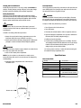
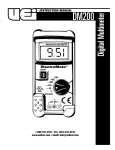
INSTRUCTION MANUAL
DL250
1-800-547-5740 • Fax: (503) 643-6322
www.ueitest.com • email: [email protected]
Introduction
The DL250 Digital Clamp-on is the all-in-one test-tool that's designed
to make quick work of HVAC/R service and industrial maintenance.
Whether you're measuring flame safeguard current, motor inrush
current, run/start capacitors, recording time-stamped temperature
highs and lows, or performing general electrical troubleshooting, the
DL250 has you covered! It's convenient size, teardrop jaw design
and ergonomic controls add speed, comfort and flexibility to your
measurement tasks.
HVAC Trade
• Check current draw in motors and compressors
• Use MIN/MAX recording in the temperature mode to
assess efficiency
• Test run/start capacitors
• Confirm low voltage control signals
• Measure flame safeguard device current draw
• Confirm power sources
• Analyze temperature and power data with the aid of the time stamp
Electrical Trade
•
•
•
•
•
•
•
•
Check for energized circuits
Balance loads
Evaluate electrical contacts
Capture motor in-rush current readings
Determine peak power demand periods
Verify line voltage stability
Monitor motors and other loads for excess hear
Check motor run/start capacitor values
Features include:
• 400 Amps Ac
• 600 Volts AC and DC
• Resistance to 40 Megohms
• Continuity
• Capacitance to 10,000 microfarods
• Temperature to 750˚F (400˚C)
• .01 µA DC resolution for flame safeguard circuit testing
• Diode check function
• Time-stamped record function
• Auto ranging with manual ranging capability
• MIN/MAX and data hold
• 1 1/3” jaw capacity
• CE and UL listed CAT III
• Three year limited warranty
DL250-MAN
Safety Notes
Before using this meter, read all safety information carefully. In
this manual the word "WARNING" is used to indicate conditions
or actions that may pose physical hazards to the user. The word
"CAUTION" is used to indicate conditions or actions that may
damage this instrument.
WARNING!
Exceeding the specified limits of this meter is dangerous and can
expose the user to serious or possibly fatal injury.
• DO NOT attempt to measure any voltage that exceeds 600 volts
with this meter - UEi offers numerous alternatives for measuring
high voltage and current
• Voltages above 60 volts DC or 25 volts AC may constitute a
serious shock hazard
• DO NOT attempt to use this meter if either the meter or the test
leads have been damaged. Send unit in for repair by a qualified
repair facility
• Test leads must be fully inserted prior to taking measurements
• Always turn off power to a circuit (or assembly) under test before
cutting, unsoldering or breaking the current path. Even small
amounts of current can be dangerous
• Always disconnect the live test lead before disconnecting the
common test lead from a circuit
• When measuring high voltage, disconnect the power source before
making test lead connections. Connect the test leads to the meter
first then to the circuit under test. Reapply power
• If any of the following indications occur during testing, turn
off the power source to the circuit under test:
• Arcing
• Flame
• Smoke
• Extreme Heat
• Smell of Burning Materials
• Discoloration or Melting of Components
• Read the safety precautions associated with the equipment being
tested and seek assistance or advice when performing
unfamiliar tasks
• Keep your fingers away from the test lead metal probe contacts
and bus-bars when making measurements - Always grip the
instrument and test-leads behind the hand guards (molded into
the probes)
• In the event of electrical shock, ALWAYS bring the victim to
the emergency room for evaluation, regardless of the victim’s
apparent recovery - Electrical shock can cause an unstable heart
rhythm that may need medical attention
P. 1
4. Range and Time Stamp Push-button: Switches meter
from auto to manual ranging. Also initiates the time stamp
function when used in conjunction with MAX/MIN/Recording.
International Symbols
5. Hold Push-button: Freezes the value displayed on the digital
read-out. This function does not work while recording is in
progress. Also turns on back light and work area light.
6. MAX/MIN Push-button: Use to cycle through recorded and
present values, and the time stamp function.
7. Clamp Lever: Opens and closes current clamp jaw.
8. Mode Push-button: Toggles the color-coded optional functions
indicated on the rotary function switch (AC to DC volts, ohms to
continuity and degrees centigrade to fahrenheit, frequency to
duty cycle).
Controls and Indicators
1
2
3
7
4
5
6
9. Rotary Function Switch: Used to power the meter on and
off, or to select the available measurement functions:
• Measures inductive AC current using the clamp
• Measures capacitance at the test lead inputs
• Measures volts AC or DC Volts at the test lead inputs
• Measures resistance or continuity at the test lead inputs
• Measures Hz and Duty Cycle
• Measures temperature with the K-type thermocouple
and adapter plug at the test lead inputs
• Measures DC microamps using the test lead inputs
8
9
10
11
12
13
15
14
1. Clamp: Used to measure inductive AC current. Opens
to 1.25" (32 mm).
NOTE: The clamp uses a high tension spring to close the
jaw. Do not allow fingers or objects to become pinched in
the base as jaw closes.
2. Conductor Alignment Marks: Used to aid in the visual
alignment of a conductor when measuring inductive
amperage. Greatest accuracy is achieved when the
conductor inside the clamp is centered at the intersection
of these marks.
3. Hand Guard: Used as a point of reference for the
operators safety.
WARNING!
Always keep your hands and fingers behind the hand guards when
measuring current on exposed conductors. Contact may result in
serious injury.
DL250-MAN
CAUTION!
When taking DC current and micro amp measurements, this meter
must be connected in SERIES with the circuit (or circuit element) under
test. NEVER CONNECT THE TEST LEADS ACROSS A VOLTAGE
SOURCE while the rotary switch is set to the microamps position. This
can cause damage to the circuit under test or this meter.
10. Off Position: Turns the meter off. Always store your meter in
the off position. If the meter will not be used for a month or more,
remove the batteries.
11. Display: Communicates function, range and value information
to the user. (See items 16 through 30)
12. 400 µA MAX FUSED: Indicates that the DC µA ranges
are fuse protected.
13. Common Terminal: The black test lead is plugged into
this terminal to supply the ground or “low” reference for all
measurements.
14. MAX 600V : Indicates the maximum voltage potential that
can be applied at the terminals.
WARNING!
DO NOT Exceed 1000 volts DC or AC-RMS at either the common or
multifunctional input ports, as measured from earth ground.
15. VΩ µA
TEMP Terminal: The red lead is
plugged into this terminal. It is used for AC/DC volts, ohms,
continuity, microamps, diode, capacitance and temperature
measurements.
P. 2
The following describes the indicators displayed by the LCD.
21 22
23
24
25
29. OFL: This symbol appears when the input value exceeds
the meters selected range or overall specification.
26 27
Operating Instructions
16
17
18
19
20
28
29
16. BAT this symbol appears when the battery needs replacement.
NOTE: A low battery will adversely affect accuracy.
17. AC: Indicates that alternating current/voltage is being measured.
18. Minus (—): I n d i cates the value measured has a negative polarity.
19. DC: Indicates that direct current/voltage is being measured.
20. AT: Indicates the meter is in the autoranging mode.
21. MAX: Indicates the meter is displaying the maximum
value recorded.
22. R Indicates the meter is currently recording the maximum and
minimum values.
23. MIN: Indicates the meter is displaying the minimum
value recorded.
24. •))): Indicates the meter is in the continuity measurement mode.
25.
Indicates the meter is in the diode test mode.
26. D.H.: Indicates the value displayed is held on screen
(the data hold button is pressed).
27. R.H.: Indicates the meter is in the manual ranging mode
(the Range button has been pressed).
28. Function and Units of Measurement:
Symbol
°C
°F
µF
mV
V
µA
A
M
K
Ω
DL250-MAN
Function or Value
Degrees Centigrade
Degrees Fahrenheit
Micro Farads
Millivolts
Volts
Micro Amps (Test Lead
Measurement Ranges)
Amps (Inductive Clamp Ranges)
Mega (Value x 1,000,000)
Kilo (Value x 1,000)
Ohms (Resistance Value)
Auto Power Off
The instrument automatically shuts off after 30 minutes of inactivity.
The meter is considered active when there is a change of at least 10
digits during the period (i.e., the meter senses a change from 24.04
volts to 24.14 volts)
To disable this function; press and hold the "MIN/MAX" or the
"RANGE" button while turning the meter on. This function will be
active in all modes, including RECORD and TIME STAMP, unless it
is disabled.
Auto / Manual Range
This instrument is capable of providing either auto (instrument
controlled), or manual (operator controlled) ranging. In the autorange
mode, the meter automatically selects the range that gives you the best
resolution of the value measured. For example, if you were measuring
a 9 volt battery that actually put out 9.6 volts, the meter would
automatically display “9.60”, although it has the ability to display “9” or
“9.6” for the same battery. The far left, or most significant digit, can
only display “0” through “3”, so “9.600” could not be displayed,
instead the symbol “0.FL” would appear on the display indicating the
measured value exceeded the range selected. The meter automatically
enters the autoranging mode when it is first turned on, or if a new
function is selected using the rotary dial. In the autoranging mode, the
symbol “AT” appears on the display.
Although the autoranging mode is easy to use, there are times that you
may prefer the manual ranging mode. For example, suppose you were
measuring a series of connectors you know had either 24 or 120 volts
AC on them. If your goal was to see which terminal had what voltage
applied, the task would go faster and easier if you set the meter to hold
the 400 volt range. To select manual range control, press the “RANGE”
push-button for approximately 1/2 second. As you release the button,
the symbol “R.H” appears at the top of the display, and an audible tone
sounds to alert you that the meter has changed ranges or modes. Each
subsequent time the RANGE button is pressed, the range increases one
step, and a tone sounds until it reaches its highest range. The next press
of the range hold button will return the meter to its lowest range.
Recording MIN/MAX
After selecting the mode and range you will be using, you can enable
the MIN/MAX recording function. This function allows you meter to
store the highest and lowest readings obtained in the following modes:
• AC Amps
• AC and DC Volts
• Ohms
• Temperature
• DC microamps
You may recall and cycle through the high and low readings or view
the measurement currently being make while you are in the record
mode. Pressing the “MIN/MAX” button locks the meter in the range it
was in at that moment and begins the recording precess. Be sure you
are in a range that can display the minimum and maximum values you
are monitoring (you may prefer to select this range manually). Each
time a new high or low value is recorded, an audible beep sounds.
P. 3
When the “MIN/MAX” button is pressed a second time, the symbol
“MAX” appears at the top of the display, while the maximum recorded
value is displayed. When the “MIN/MAX” button is pressed a third
time, the “MIN” symbol appears at the top of the display, while the
minimum recorded values are displayed. If a new high or low value is
recorded while you are viewing the “MIN” or “MAX”, that value will
be displayed. Pressing the button again will return you to monitoring
real-time reading. Cycling through these modes will not effect the values
in memory. To exit the record mode, press and hold the “MIN/MAX”
button for two seconds. The meter will return to the autoranging mode.
Time Stamp
The time stamp feature makes unattended monitoring simple. This
function you to display the hour and minute that a high and low value
was recorded, within a 24-hour period.
The first step in using the time stamp is to begin recording the dat you
wish to time stamp, as prescribed in the “recording MIN/MAX” section.
Press the “TIME STAMP” button to start the counter. Four zeros,
(00:00) like those on a digital stop watch, appear on the LCD. The times
indicated for the minimum an maximum recorded values are relative
to when the time stamp feature was engaged. To view the time that a
value reached its maximum, press the “MIN/MAX” button until MAX
appears on the LCD, then press the “TIME STAMP” button. The
elapsed time, in hours and minutes, will now be displayed. Similarly,
if you wish to view the time that the minimum value was recorded,
press the “MIN/MAX” button until MIN appears on the LCD, then
press the “TIME STAMP” button. To view the total time that has
elapsed from initiating the time stamp, cycle the “MIN/MAX” button
until neither MAX, nor MIN appears on the LCD, then press the
“TIME STAMP” button.
Example: A local company is analyzing its peak power requirements.
You have been asked to provide them with the specific time, and the
values, of the highest and lowest power demands. To accomplish
this task:
1. Set the rotary function switch to measure AC amperage
(using the inductive clamp).
2. Press the “MIN/MAX” button (to record values).
3. Press the “TIME STAMP” button to begin monitoring time
(00:00 appears on the LCD).
4. Note the time of day (i.e., 8:00 AM), and press the “TIME STA MP”
button to view real-time data.
5. Clamp the meter around the main power feed.
6. Return the next morning and not the values. Hypothetically:
A. Press the “MIN/MAX” button once; the “MAX” symbol
appears at the top of the LCD and a value of “235.4” is
displayed. Now press the “TIME STAMP” button; the time
stamp value of “07:20” is displayed. This means seven hours,
20 minutes after the time stamp was engaged, (in this case
3:20 PM), the highest amperage of that 24 hour period
(235.4 amps), was measured.
DL250-MAN
B. Press the “TIME STAMP” button to return the display to the
measured values. Press the “MIN/MAX” button; the “MIN”
symbol appears at the top of the LCD and a value of “088.3”
is displayed. Press the “TIME STAMP” button; the time stamp
value of “17:32” is displayed. This means that 17 hours, 32
minutes after the time stamp was engaged, in this case 1:32
AM in the following morning, the lowest amperage of that
24 hour period (88.3 amps) was measured.
1. The maximum time value that can be recorded is “23:59.” If 24
hours have not elapsed, you can use the total elapsed time,
(displayed when the “TIME STAMP” button is pressed while the
meter is displaying real-time values in the record mode), to
calculate the time of day information.
To turn off the time stamp: press and hold the “TIME STAMP”
button for two seconds, or rotate the rotary function select switch to any
other position.
Hold
The “HOLD” button freezes the reading displayed on the LCD at the
moment it is pressed. To engage data hold, press the “HOLD” button,
located on the side of the instrument. When this function is active, the
symbol “D.H” appears on the digital display. To cancel data hold, press
the “HOLD” button again, or select any other measurement function
using the rotary function select switch.
Rotary Function Select Switch
The rotary function select switch is used to select the primary
measurement mode and to turn the meter on and off. While this
meter is manufactured with a number of built in fail-safe, the
potential to damage the meter, blow a fuse, or sustain serious
personal injury due to improper use does exist.
WARNING!
Set the rotary function select switch to the appropriate setting before
connecting test leads, or applying power to circuits under test.
CAUTION!
When taking DC current measurements, this meter must be connected
in SERIES with the circuit (or circuit element) under test. Never connect
the test leads across a voltage source while the rotary switch is set to
the microamps position. This can cause damage to the circuit under test
or this meter.
Measuring Inductive Current
To measure inductive AC current, place the meter in the AC amp
position as shown in the controls and indicators section of this
manual. The inductive current measurement mode relies on the
induced electromagnetic field that occurs when electricity flows through
a conductor.
Prepare for measurement by separating a single live conductor from
any other phase, neutral or ground conductor. Zero the meter by
pressing the “DATA HOLD” button on the side of the of the meter for
two seconds. Squeeze the lever, and place the conductor in the open
jaws. To attain the most accurate reading, ensure the conductor is
centered in the jaws of the clamp, and the jaws are closed tight. The
conductor must be able to fit inside the 1.25” (32 mm) fully open jaws.
P. 4
The maximum limit for this function is 400 amps AC. Too much
current will saturate the ferrous material in the clamp, and adversely
affect accuracy.
WARNING!
DO NOT attempt to take any unknown voltage or current measurements
that may be in excess of this meter’s maximum limits.
This meter is designed for measuring current and voltage in commercial,
residential, and light industrial applications. To avoid the risk of electrical
shock and instrument damage, input voltages must not exceed 600 volts
DC or AC (RMS). Some industrial applications exceed the limitations of this
meter. Dange rous power surges may occur on industrial power lines. If the
maximum measurement value is unknown or is likely to exceed the rated
limit of this meter, DO NOT attempt to make that measurement with this
meter. Consider using an optional high voltage probe for high power
situations. Use caution when connecting the current clamp on
uninsulated conductors.
Measuring Voltage
WARNING!
To avoid the risk of electrical shock and instrument damage, input voltage s
must not exceed 600 volts DC or AC (RMS). DO NOT attempt to take any
unknown voltage measurements that may be in excess of these values.
NOTE: When taking voltage measurements your meter must be
connected in parallel to the circuit, or circuit element, under test.
To improve the accuracy of DC voltage measurements taken in the
presence of AC voltages, (such as measuring the DC offset voltage of an
amplifier in the presence of an AC signal), measure the AC voltage first.
Note the AC voltage range and select a DC voltage range that is the
same or higher than the AC voltage accuracy be preventing the input
protection circuits from being activated.
To measure DC or AC volts:
1. Set the rotary function switch to the “V” position, and select DC or
AC using the red “MODE” button. If you are in the manual ranging mode, and you do not know the maximum value of the voltage to be measured, start at the highest range and reduce the setting as required to obtain a satisfactory reading.
2. Plug the red lead into the meter’s multifunction terminal on the
right, and the black lead into the meter’s COM terminal on the left.
3. Disconnect the power from the circuit to be tested.
4. Connect the test leads to the circuit to be tested.
Measuring Three-Phase AC Volts
WARNING!
This meter is primarily designed to measure residential, commercial
and light industrial AC voltage. When measuring 3-phase circuits,
line-to-line, the value of the voltage is actually higher than the rated
line-to-ground voltage at any one phase. Exceeding the maximum AC
(RMS) rating of this meter is dangerous and could result in serious or
fatal injury.
To find the RMS voltage, line-to-line, on a 3-phase power source,
multiply the rated line-to-ground voltage by the square root of 3
(approx. 1.732).
For example, if you connect this meter to a 480 volt, 3-phase, power
source (i.e. 480 volts line-to-ground), the total available voltage,
line-to-line, is about 832 volts AC (480 x 1.732). Severe damage to
the instrument or serious personal injury may result by attempting to
measure this voltage.
Measuring Resistance
CAUTION!
Turn off power and discharge all capacitors on the circuit to be tested
before attempting “in circuit” resistance measurements. Failure to do
so may result in equipment or instrument damage. The resistance
measuring circuit applies a small, known value of constant current
through the unknown resistance. It then uses the voltage developed
across the measured circuit to calculate resistance. It is therefore critical
to both the welfare of the meter, and the accuracy of the measurement
that you remove all power to the circuit under test when making
resistance measurements. If any voltage is present in the test circuit,
whether from a conventional power supply, or energy stored in a
capacitor, an erroneous reading will result. This meter may be
damaged if more than 600 volts are present.
NOTE: When measuring critically low ohm values, touch tips of test
leads together and record the reading. Subtract this value from the
total circuit resistance to obtain the most accurate value.
When measuring large resistance values, the reading may be unstable
due to environmentally induced electrical noise.
If this occurs, connect the resistor directly to the input terminals of the
meter in place of the test leads. If may also be possible to use an
electrical shield on the resistor that is connected to the same ground
plane as the “COM” input terminal to obtain a stable reading.
For resistance measurements above one megohm the display might take a
f ew seconds to stabilize. This is normal for high resistance readings.
5. Reapply power to the circuit. The measured voltage will be displayed.
6. If the input to the red multifunction terminal is lower (more
negative) than the black COM input terminal, a minus polarity sign
will appear on the left of the display.
7. Disconnect power to the circuit before removing the test leads
from the circuit.
DL250-MAN
CAUTION!
This meter has a circuit to protect the resistance ranges from up to 600
volts. however, to prevent accidentally exceeding the protection circuits
rating and to ensure a correct measurement, NEVER CONNECT THE
TEST LEADS TO A SOURCE OF VOLTAGE when the rotary switch is
set to ohms, continuity or diode test functions.
P. 5
The voltage or current applied during resistance measurements could
damage some devices. Typically, the voltages applied in the resistance
ranges vary from 3 volts in the lowest range to 0.5 volts in the highest
range. Current will typically vary from 800 µA at the lowest range to 30
µA at the highest range.
To measure resistance:
1. Insert the test leads into the meter, and turn off the power to the
circuit under test. Voltage across the circuit, from any source, will
cause an erroneous reading.
2. Set the rotary switch to the resistance/continuity function. The
meter defaults to the resistance measurement mode.
3. Touch the test probes to the test points and read the display. The
meter beeps as it seeks the correct range to measure the circuits
resistance. Be sure you have good contact between the test leads
and the circuit. Dirt, oil, solder-flux or other foreign matter alters
the reading value.
NOTE: During continuity or resistance measurements, polarity does not
matter. If may be preferable to use the manual range mode to test
some circuits that are susceptible to damage at low voltages/currents.
Measuring Continuity
Use this mode to make quick checks for continuity or electrical circuits,
such as wiring, speaker cables, connections, switches or relays. In the
continuity mode, an audible tone sounds when the value measured is
approximately 50Ω or less.
To test for continuity, follow these steps:
1. Set the rotary switch to the ohms/continuity function.
2. Press the red “MODE” button to bring the
symbol up on
the top of the display, indicating that the continuity mode has
been selected. The range is preset to the 400Ω scale and can not
be revised.
3. Place one probe to each side of the circuit to be tested. If
approximately 50Ω or less resistance is in the circuit, the meter
sounds a continuous tone.
Testing Diodes
The diode test function allows you to check diodes, transistors and other
semiconductor devices for opens, shorts and normal operation.
Your meter is designed to apply enough voltage, in the forward biased
direction, to allow current flow. All diodes use up or “drop” a small
amount of the supplied voltage when they are forward biased. When
they are reverse biased they drop nearly all of the supplied voltage. The
voltage drop is normally around 0.4 V for germanium diodes and 0.6 V
for silicon diodes. When the diode is reverse biased, the meter should
indicate the over-range symbol (OFL).
To determine the condition of semiconductor devices:
1. Insert the test leads into the meter (red to the multifunction port
on the right, and black to the common port on the left).
2. Select the diode test function on the rotary function switch.
3. Connect the red test lead to the anode side of the diode, and the
black to the other. There is normally a printed black band around
the anode of a diode.
4. Note the displayed value.
5. Reverse the red and black test leads. Again, note the displayed value.
6. If the digital reading in the first (forward biased) direction
indicates some measurable value, and the reading in the reverse
biased direction shows an over-range (OFL) the diode is good.
7. If the displayed value is low, or all zeros, in both directions, the
diode is probably shorted.
8. If the display indicated an overload (OFL) in both directions, the
diode is probably open. Some diodes, such as those used in
microwave ovens, require a higher biasing voltage than this
meter supplies. UEi has high-power diode test lead adapter sets
accessories available.
Measuring Temperature
Using the K-type thermocouple adapter and the thermocouple, this
meter will display temperatures from 40˚ to 750˚F.
To measure temperature:
1. Obtain the K-type thermocouple adapter and the thermocouple
from the accessories provided.
NOTE: A wide variety of optional temperature probes are
available from UEi.
2. Insert the adapter into the meter, observing polarity.
3. Insert the temperature probe into the adapter. Again, observe polarity.
CAUTION!
DO NOT connect the test leads to a source of voltage when the diode
test function is selected.
Diodes, and other P/N junction devices, allow current to flow easily in
one direction and prevent current flow in the other direction. When a
diode is forward biased, it allows current to flow. When it is reverse
biased, it prevents current flow.
DL250-MAN
4. Place the rotary function switch in the “TEMP” position.
5. Select either the Fahrenheit (˚F) scale or the Centigrade (˚C) scale
using the red “MODE” button.
6. If necessary, prepare a surface to place the hot temperature probe,
once the measurement is made.
7. Using the precautions the task warrants, place your temperature
probe, or thermocouple in position to measure the appropriate
surface, liquid or gas (probes are available for any of these), and
make your measurement.
P. 6
Measuring Capacitance
This meter measures capacitors, such as those used as motor-run-start
capacitors, ranging in value from .001 to 10,000 microfarads (µf).
WARNING!
Capacitors should be completely discharged prior to testing.
To measure AC or DC current flow (in amps):
1. Ensure power is off to the circuit to be tested.
2. Insert the test leads into the meter (red to the multifunction port
on the right, and black to the common port on the left).
3. Set the rotary switch to the DC microamps (test leads) position.
Some electronic devices use capacitors in circuits that are designed to
increase voltage. By design, a capacitor stores energy. If a capacitor has
been charged at greater than 600 volts, your meter may be damaged by
attempting to measure it. Larger capacitors may store enough energy to
cause injury if they are discharged through the body. Use a conductive
device to dissipate the charge on capacitors. Large capacitors should be
“bled” by using a resistive load between terminals to slowly eliminate the
charge. Smaller capacitors may be directly shorted using a metallic object.
4. You may manually select either the 40 or 400 µA range, or leave
it in the autoranging mode.
To measurecapacitance:
7. Apply power to the circuit.
5. Touch the leads together and press the “HOLD” button on the
side of the meter for a minimum of two seconds to zero the meter.
6. Break the circuit as described earlier and connect the meter leads
to the appropriate points. Some gas furnace models have special
adapters for flame safeguard testing.
1. Discharge the capacitor to be tested as prescribed above.
8. Note your measurement value.
2. Isolate the capacitor by lifting at least one of its two legs away
from the circuit.
9. Disconnect power to the circuit. Do not remove the leads from
the circuit until power is disconnected.
3. Insert the test leads into the meter (red to the multifunction port
on the right, and black to the common port on the left).
4. Select the capacitance
.
5. Connect the red test lead to one side of the capacitor, and the
black to the other.
6. Note the displayed value. In the autoranging mode, it takes
approximately 10 seconds to settle on a value for a capacitor. In
the manual ranging mode, measurements are considerably faster.
Measuring DC Microamps
The DC microamp position has been incorporated in this meter to
permit flame safeguard testing, as well as other low current DC
measurements. DC current of 0.1 microamps (µA) to 400 µA can
be measured.
Maintenance
Service
WARNING!
Repair and service of this instrument is to be performed by qualified
personnel only. Improper repair or service could result in physical
degradation of the meter. This could alter the protection from electrical
shock and personal injury this meter provides to the operator. Perform
only those maintenance tasks that you are qualified to do.
These guidelines will help you attain long and reliable service from
your meter:
1. Calibrate your meter annually to ensure it meets original
performance specifications.
CAUTION!
The current functions are protected by a 250 volt rated fuse. To avoid
damage to the instrument, do not measure current sources having
open circuit voltages greater than 250 volts DC or AC.
2. Keep your meter dry. If it gets wet, wipe it dry immediately.
NOTE: When taking current measurements, this meter must be
connected in series with the circuit (or circuit element) under test.
NEVER CONNECT THE TEST LEADS ACROSS A VOLTAGE
SOURCE while the rotary switch is set to the microamps position.
This can cause damage to the circuit under test or this meter.
4. Although your meter is built to withstand the rigors of daily use, it can
be damaged by severe impacts. Use reasonable caution when using
and storing the meter.
To measure current, you must break the circuit under test and make
the meter part of the circuit. Two connection points are created when
a circuit is broken. On one side is the power source and the other is
the load.
3. Whenever pra c t i cal, keep the meter away from dust and dirt, which
can cause premature wear and collect on internal components.
NOTE: When servicing the meter, use only the replacement
parts specified.
Battery: 9V, NEDA 1604 or IEC 6LR 61
Fuse: Fuse 500 milliamp, 250 V, f500mA
Test lead set: ATL55
A minus sign will be displayed if the current is flowing opposite to the
connection polarity.
DL250-MAN
P. 7
Cleaning and Decontamination
Periodically clean your meter’s case using a damp cloth. DO NOT use
abrasives, cleaning solvents or strong detergents, as they may damage
the finish or affect the reliability of the structural components.
Fuse Replacement
The DC µA position is protected by a 400 mA fuse. If this fuse blows the
meter will display all zeros (example, 00.00 mA) on the LCD when the
DC µA function is selected, regardless of input.
Battery Replacement
Always use a fresh replacement battery of the specified size and ty p e .
Immediately remove the old or weak battery from the meter and dispose
of it in accordance with your local disposal regulations. Old or defective
batteries can leak chemicals that corrode electronic circuits.
WARNING!
To avoid the potential of electric shock or personal injury, disconnect
the test probes from any potential power source before removing the
fuse. Replace the blown fuse with the fuse specified for this meter only.
WARNING!
To avoid electric shock, be sure to turn off the meter’s power and
disconnect both test leads from any equipment before you remove or
install batteries.
To replace a blown fuse, follow these procedures:
1. Turn off power to the circuit under test.
2. Turn off the meter.
3. Disconnect the test leads from the circuit or component under test.
To install a new battery, follow these procedures:
1. Remove the screw from the battery compartment cover on the
back (lower half) of the meter and lift the cover (Fig 1).
2. Remove and discard the old battery. Always dispose of old batteries
promptly in a manner consistent with local disposal regulations.
WARNING!
Under NO circumstance should you expose batteries to extreme heat or
fire as they may explode and cause injury.
4. Open the battery/fuse compartment cover. The fuse is visible above
the battery above the battery compartment (Fig 1).
5. Pull the fuse from the fuse holder.
6. Check the fuse by confirming that there is no continuity. The ohms
and continuity functions will work with the fuse out. Do not attempt
to make circuit measurements with the battery cover off. Live
voltages may be present at the fuse holder.
7. If necessary, insert a new fuse, or replace the fuse that tested good.
8. Reattach the battery compartment cover.
3. Place a fresh 9V battery in the compartment.
NOTE: If you do not plan to use the meter for a month or more,
remove the battery and store it in an area that won’t be damaged by
a leaking battery.
4. Reattach the battery compartment cover to the meter and
reinstall the screw.
Specifications
Measurement limits
AC Amps
DC Milliamps
AC Voltage
DC Voltage
Resistance
Capacitance
Temperature
Continuity
0.3 A to 400 A
0.01 µA to 400 µA
1 mV to 600 V
1 mV to 600 V
0.1 Ω to 400 Ω
0.001 µf to 10,000 µf
-40˚ to 750˚F (-40˚ to 400˚C)
(500˚F with thermocouple provided)
Tone sounds at approximately 50 Ω
or less
Remove cover
(Fig 1)
DL250-MAN
P. 8
Maximum voltage between any
terminal and earth ground
Digital display
Storage temperature
Operating temperature
Altitude
Relative humidity
B a t t e ry type
B a t t e ry life
M aximum conductor size
M aximum jaw opening
Size (H x W x L, in mm)
Weight (approximate)
V i b ration and shock
Case protection
S a f e tystandards
600 V DC or AC RMS
4000 Count - Updates 4 times
per second
-4˚ to 140˚F (-20˚ to 60˚)
32˚ to 113˚F (0˚ to 45˚C)
= or < 6560’ (2000 M)
0% to 80% at 32˚ to 95˚F (0˚ to 35˚C)
0% to 70% at 95˚ to 113˚F (35˚ to 45˚C)
9V, NEDA, 1604 or 6LR 61
80 hours (alkaline)
1. 25” (32 mm) up to 750 MCM
1. 25” (32 mm)
235 x 86.5 x 45
.95 lbs (430 g)
Designed to MIL-T 28800 for a
class II instrument
IEC 529, IP 30
Designed to UL 3III (overvoltage
ca t e g o ry III) CSA C 22.2 no 1010-1,
and both IEC 1010 - 2 - 0 32, and
the EMC directive
Standard & Optional Accessories
Standard
Test leads . . . . . . . . . . . . . . . . . . . . . . . . . . . . . . . . . . . . . . . . .ATL55
Instruction manual . . . . . . . . . . . . . . . . . . . . . . . . . . . . . . . . .DL250-MAN
Temperature probe connection adapter . . . . . . . . . . . . . . . .ATT70
Thermocouple . . . . . . . . . . . . . . . . . . . . . . . . . . . . . . . . . . . . .ATT29
Optional
Flame safeguard test kit . . . . . . . . . . . . . . . . . . . . . . . . . . . . .ATLFSG
Microwave diode booster test lead . . . . . . . . . . . . . . . . . . . .ATL60
Plug-in line splitter . . . . . . . . . . . . . . . . . . . . . . . . . . . . . . . . .ALS1
Hard carrying case (service kits) . . . . . . . . . . . . . . . . . . . . . .AC506
Digital tachometer adapter . . . . . . . . . . . . . . . . . . . . . . . . . .DPM2K
The specifications listed in the following table are based on an instrument operating in an ambient temperature of between 65 and 90˚F, at a
relative humidity of less than 80%, and within one year of calibration.
The “accuracy” column indicates the percent of possible error based on
the reading displayed, plus an additional allowance for error based on
the value of the least significant digits of the selected range. This is stated as (±X% + X dgts).
AC readings displayed on this meter are average responding, True-RMS
indicating. They are based on a true sinusoidal waveform.
Function
AC Amps
(50 Hz to 400 Hz)
DC
Low Amps
DC Volts
Range
40 A
400 A
40 µA
400 µA
4V
40 V
400 V
600 V
AC Volts
4V
(50 Hz to 400 Hz)
40 V
400 V
600 V
Ohms
400 Ω
4K Ω
40K Ω
400K Ω
4Ω
40 Ω
Capacitance
1 µF
10 µF
100 µF
1000 µF
10000 µF
Temperature
-40˚ to 15˚F
15˚ to 750˚F
Continuity
Diode check
DL250-MAN
Resolution
0.01 A
0.1 A
0.01 µA
0.1 µA
1 mV
10 mV
100 mV
1V
1 mV
10 mV
100 mV
1V
100 Ω
1Ω
10 Ω
100 Ω
1Ω
10 Ω
0.001 µF
0.01 µF
0.1 µF
1 µF
1 µF
0.1˚F
0.1˚F
Open circuit test voltage
Threshold: Approx:
Open circuit test voltage
M ax test current
Accuracy
3.0% ±20 dgts
2.0% ±5 dgts
1.0% ±5 dgts
1.5% ±2 dgts
0.9% ±2 dgts
Overload
400 A
continuous
400 µA/250 V
600 V RMS
0.9% ±3 dgts
0.9% ±3 dgts
600 V
1.2% ±3 dgts
1.5% ±5 dgts
1.7% ±5 dgts
600 V
2.5% ±15 dgts
15% ±100 dgts
5% ±5˚F
1% ±3˚F
30 V AC or
60 V DC
<2.7 V
< 50 Ω
<3.3 V
3.0 mA
600 V
600 V
P. 9
DL250
Digital Clamp-On Multimeter
Limited Warranty
The DL250 is warranted to be free from defects in materials and workmanship for a period
of three years from the date of purchase. If within the warra n ty period your instrument
should become inoperative from such defects, the unit will be repaired or replaced at UEi’s
option. This warra n ty covers normal use and does not cover damage which occurs in
shipment or failure which results from alteration, tampering, accident, misuse, abuse,
neglect or improper maintenance. Batteries and consequential damage resulting from failed
batteries are not covered by warra n ty.
Any implied warranties, including but not limited to implied warranties of merchantability
and fitness for a particular purpose, are limited to the express warranty. UEi shall not
be liable for loss of use of the instrument or other incidental or consequential damages,
expenses, or economic loss, or for any claim or claims for such damage, expenses or
economic loss. A purchase receipt or other proof of original purchase date will be required
before warra n ty repairs will be rendered. Instruments out of warra n ty will be repaired
(when repairable) for a service charge. Return the unit postage paid and insured to:
1-800-547-5740 • FAX: (503) 643-6322
www.ueitest.com • Email: [email protected]
This warranty gives you specific legal rights. You may also have other rights which vary from
state to state.
PLEASE
RECYCLE
Copyright © 2007 UEi
DL250-MAN 1/07