1
Installation Manual
LBI-38636S
MASTR III
®
Conventional Base Station
LBI-38636S
NOTE
Repairs to this equipment should be made only by an authorized service technician or facility designated by the supplier.
Any repairs, alterations or substitution of recommended parts made by the user to this equipment not approved by the
manufacturer could void the user’s authority to operate the equipment in addition to the manufacturer’s warranty.
NOTICE!
The software contained in this device is copyrighted by M/A-COM Private Radio Systems, Inc. Unpublished rights are
reserved under the copyright laws of the United States.
This manual is published by M/A-COM Private Radio Systems, Inc., without any warranty. Improvements and changes to this manual necessitated by
typographical errors, inaccuracies of current information, or improvements to programs and/or equipment, may be made by M/A-COM Private Radio
Systems, Inc., at any time and without notice. Such changes will be incorporated into new editions of this manual. No part of this manual may be
reproduced or transmitted in any form or by any means, electronic or mechanical, including photocopying and recording, for any purpose, without the
express written permission of M/A-COM Private Radio Systems, Inc.
Copyright 1992-2002 M/A-COM Private Radio Systems, Inc. All rights reserved.
3
LBI-38636S
TABLE OF CONTENTS
Page
PRODUCT SPECIFICATION FOR CE MARKED EQUIPMENT ..................................................................................5
MAXIMUM PERMISSIBLE EXPOSURE (MPE) LIMITS..............................................................................................6
DETERMINING MPE RADIUS....................................................................................................................................6
SAFETY TRAINING INFORMATION ............................................................................................................................6
STATION SPECIFICATIONS (GENERAL).....................................................................................................................8
PUBLICATIONS INDEX ..................................................................................................................................................9
SAFETY SUMMARY......................................................................................................................................................11
GROUND THE EQUIPMENT.....................................................................................................................................11
REPLACEMENT OF PLUG-IN CIRCUIT MODULES .............................................................................................11
ELECTROSTATIC DISCHARGE - SENSITIVE COMPONENTS............................................................................11
DO NOT SUBSTITUTE PARTS OR MODIFY PRODUCT.......................................................................................12
INTRODUCTION ............................................................................................................................................................12
CABINET .....................................................................................................................................................................12
STATION POWER SUPPLY.......................................................................................................................................12
TRANSMITTER/RECEIVER SHELF.........................................................................................................................12
TRANSMITTER POWER AMPLIFIER......................................................................................................................12
UNPACKING EQUIPMENT ...........................................................................................................................................12
SITE PREPARATION AND INSTALLATION ..............................................................................................................12
CABINET INSTALLATION .......................................................................................................................................12
Single 37-inch Cabinet Installation...........................................................................................................................12
Double Stacked 37-inch Cabinet installation ............................................................................................................13
ELECTRICAL CONNECTIONS .................................................................................................................................14
AC Power..................................................................................................................................................................14
Microphone...............................................................................................................................................................14
Antenna.....................................................................................................................................................................14
TELEPHONE LINE CHARACTERISTICS ................................................................................................................14
Telephone Lines........................................................................................................................................................14
Types Of Voice Grade Lines ....................................................................................................................................14
Tone Remote Control Systems .................................................................................................................................17
Voting System Considerations..................................................................................................................................18
Ordering Voice Grade Telephone Lines ...................................................................................................................18
Telephone Company Ordering Information..............................................................................................................19
TELEPHONE LINE INSTALLATION .......................................................................................................................19
DC Remote Installation.............................................................................................................................................19
E & M Signaling .......................................................................................................................................................19
Tone Remote Installation ..........................................................................................................................................20
STATION SETUP ............................................................................................................................................................24
SETUP PROCEDURE..................................................................................................................................................24
ALIGNMENT PROCEDURE ......................................................................................................................................26
AUDIO ROUTING AND ADJUSTMENTS....................................................................................................................29
TX AUDIO LEVEL ADJUSTMENT...........................................................................................................................29
REMOTE CONTROLLER TO STATION CONTROL PANEL ADJUSTMENTS....................................................39
LINE OUT LEVEL ADJUSTMENT ...........................................................................................................................39
LINE IN LEVEL ADJUSTMENT ...............................................................................................................................39
DSP LEVEL ADJUSTMENTS ....................................................................................................................................39
REPEATER PANEL INSTALLATION.......................................................................................................................40
CSI Model 32 Repeater Panel...................................................................................................................................40
Zetron 38A Repeater Panel .......................................................................................................................................40
ACCESSORIES................................................................................................................................................................42
4
LBI-38636S
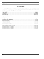
ILLUSTRATIONS
Page
Figure 1 - Typical 37-inch MASTR III Stations............................................................................................................... 11
Figure 2 - 37 Inch Mounting Footprint............................................................................................................................. 13
Figure 3 - 37-Inch Cabinet................................................................................................................................................ 13
Figure 4 - Stacked 37-Inch Cabinets
13
Figure 5 - Microphone Connections ................................................................................................................................. 14
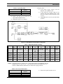
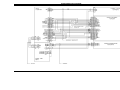
Figure 6 - T/R Shelf Connections..................................................................................................................................... 15
Figure 7 - Typical E & M Signaling Application ............................................................................................................. 21
Figure 8 - METHOD 1 (Single Metallic Pair) .................................................................................................................. 22
Figure 9 - METHOD 2 (Single Metallic, Earth Ground).................................................................................................. 22
Figure 10 - METHOD 3 (Metallic Control Pair, Audio Pair)........................................................................................... 23
Figure 11 - METHOD 4 (Full Duplex Metallic TX Pair)................................................................................................. 23
Figure 12 - Telephone Line Connections ......................................................................................................................... 24
Figure 13 - 3-Wire Adapter .............................................................................................................................................. 24
Figure 14 - Antenna Installation ....................................................................................................................................... 25
Figure 15 - MASTR III System Module Pot Alignment .................................................................................................. 27
Figure 16 - T/R Shelf Interface Board .............................................................................................................................. 32
Figure 17 - T/R Shelf Interface Board (Rev. A) ............................................................................................................... 35
Figure 18 - T/R Shelf Interface Board ( Rev. C) .............................................................................................................. 38
PRODUCT SPECIFICATION FOR CE MARKED EQUIPMENT
The MASTR® III Base Station and Auxiliary Receiver conform to the following Product Specifications.
EUROPEAN STANDARDS:
Safety:
EMC:
TTD:
EN60065 (220 VAC applications only)
prETS 300 279 (August 1995)
Not Applicable
SUPPLEMENTARY INFORMATION:
The MASTR III Base Station and Auxiliary Receiver may be used in both trunked and conventional applications. Neither the
MASTR III Base Station nor the Auxiliary Receiver may be connected to leased lines in Europe without an additional linebarrier protection device.
5
LBI-38636S
MAXIMUM PERMISSIBLE EXPOSURE (MPE) LIMITS
Do not transmit with this basestation and antenna when persons are within the MPE Radius of the antenna. The MPE Radius
is the minimum distance from the antenna axis that ALL persons should maintain in order to avoid RF exposure higher than
the allowable MPE level set by the FCC.
WARNING
FAILURE TO OBSERVE THESE LIMITS MAY ALLOW ALL PERSONS WITHIN
THE MPE RADIUS TO EXPERIENCE RF RADIATION ABSORPTION, WHICH
EXCEEDS THE FCC MAXIMUM PERMISSIBLE EXPOSURE (MPE) LIMIT. IT IS
THE RESPONSIBILITY OF THE BASESTATION OPERATOR TO ENSURE THAT
THE MAXIMUM PERMISSIBLE EXPOSURE LIMITS ARE OBSERVED AT ALL
TIMES DURING BASESTATION TRANSMISSION. THE BASESTATION
OPERATOR IS TO ENSURE THAT NO BYSTANDERS COME WITHIN THE
RADIUS OF THE MAXIMUM PERMISSIBLE EXPOSURE LIMITS SHOWN BELOW.
DETERMINING MPE RADIUS
THE MAXIMUM PERMISSIBLE EXPOSURE RADIUS HAS BEEN ESTIMATED TO BE A RADIUS OF 24 FEET
MAXIMUM ASSUMING THE HIGHEST EFFECTIVE RADIATED POWER (ERP) ALLOWABLE UNDER FCC
RULES FOR BASESTATION ANTENNA INSTALLATIONS. THIS ESTIMATE IS MADE ASSUMING
MAXIMUM ALLOWABLE ERP LEVEL BY THE FCC AND 100 PERCENT DUTY CYCLE. THE MPE
CALCULATIONS WERE MADE ASSUMING WORST CASE IN EACH BAND WITH RESPECT TO
FREQUENCY, ERP AND LIMIT. THE MAXIMUM ALLOWABLE ERP WAS DETERMINED FROM THE
APPLICABLE PART 90 RULES REGARDING POWER LIMITATION ( 90.205, 90.309, 90.635 ). THE LIMIT
USED WAS FOR UNCONTROLLED EXPOSURE. THE FORMULA USED WAS DERIVED FROM OET 65,
SECTION 2, EQUATION 4.
SAFETY TRAINING INFORMATION
WARNING
YOUR
M/A-COM
MASTR
III
BASESTATION
GENERATES
RF
ELECTROMAGNETIC ENERGY DURING TRANSMIT MODE. THIS BASESTATION
IS DESIGNED FOR AND CLASSIFIED AS “OCCUPATIONAL USE ONLY”
MEANING IT MUST BE USED ONLY IN THE COURSE OF EMPLOYMENT BY
INDIVIDUALS AWARE OF THE HAZARDS AND THE WAYS TO MINIMIZE SUCH
HAZARDS. THIS BASESTATION IS NOT INTENDED FOR USE BY THE “GENERAL
POPULATION” IN AN UNCONTROLLED ENVIRONMENT. IT IS THE
RESPONSIBILITY OF THE BASESTATION OPERATOR TO ENSURE THAT THE
MAXIMUM PERMISSIBLE EXPOSURE LIMITS DETERMINED IN THE PREVIOUS
SECTION ARE OBSERVED AT ALL TIMES DURING TRANSMISSION. THE
BASESTATION OPERATOR IS TO ENSURE THAT NO BYSTANDERS COME
WITHIN THE RADIUS OF THE MAXIMUM PERMISSIBLE EXPOSURE LIMITS.
This basestation has been examined and complies with the FCC RF exposure limits when persons are beyond the MPE radius
of the antenna. In addition, your M/A-COM basestation complies with the following Standards and Guidelines with regard to
RF energy and electromagnetic energy levels and evaluation of such levels for exposure to humans:
• FCC OET Bulletin 65 Edition 97-01 Supplement C, Evaluating Compliance with FCC Guidelines for Human
Exposure to Radio Frequency Electromagnetic Fields.
• American National Standards Institute (C95.1 – 1992), IEEE Standard for Safety Levels with Respect to Human
Exposure to Radio Frequency Electromagnetic Fields, 3 kHz to 300 GHz.
6
LBI-38636S
•
American National Standards Institute (C95.3 – 1992), IEEE Recommended Practice for the Measurement of
Potentially Hazardous Electromagnetic Fields – RF and Microwave.
TO ENSURE THAT YOUR EXPOSURE TO RF ELECTROMAGNETIC ENERGY IS
WITHIN THE FCC ALLOWABLE LIMITS FOR OCCUPATIONAL USE, ALWAYS
ADHERE TO THE FOLLOWING GUIDELINES:
CAUTION
DO NOT operate the basestation with an antenna that would cause an ERP in excess of that
allowable by the FCC.
7
LBI-38636S
STATION SPECIFICATIONS
(GENERAL)
Width
Depth
Weight (note 1)
37-INCH
Height 37.0 inches
21.5 inches
18.25 inches
150 lbs (68 kg)
69-INCH
69.1 inches
23.1 inches
21.0 inches
Rack Units (RU) (note 2)
Cabinet capacity
Radio
17 RU
8 RU
33 RU
8 RU
CABINET
Duty Cycle (EIA)
(continuous)
Tx and Rx at 100%
Operating Temperature
Humidity (EIA)
AC Input Power
-30°C to +60°C
90% at 50°C
5 Amps at 120 Vac (-20%) 60 Hz
or
3 Amps at 230 Vac (-15%) 50 Hz
DC Input Power
33 Amps at 13.8 Vdc (transmit, full power)
25 Amps at 13.8 Vdc (transmit, half power)
1.6 Amps at 13.8 Vdc (receive only, standBy)
1.75 Amps at 13.8 Vdc (receive only, 1 watt at
service speaker)
Service Speaker
1 watt at 8 ohms
Service Microphone
Dynamic
Notes:
1. Typical station consists of:
a. One T/R Shelf with plug-in modules.
b. One Power Amplifier.
c. One power supply unit.
d. One cabinet with doors.
2. One rack unit equals 1.75 inches.
INTERFACE
Line Interface
Line Interface
Line Cancellation
2-wire or 4-wire (programmable)
(2-wire) 20 dB amplitude only (programmable)
Line Input (line to transmitter)
Line Terminating Impedance
Line Input Level (adjustable)
Frequency Response
600 ohms (2-wire or 4-wire)
-20 dBm to +11 dBm
300 Hz to 3000 Hz
Line Input (receiver to line)
Line Terminating Impedance
Line Output Level (adjustable)
Frequency Response
Remote Control (Tone)
Control Tones (Hz)
600 ohms (2-wire or 4-wire)
zero output to +11 dBm (ref at 1 kHz)
300 Hz to 3000 Hz, ±1 dB
1050, 1150, 1250, 1350, 1450, 1550, 1650, 1750,
1850, 1950, 2050, & 2175
Secur-it
2175 Hz
Function
Programmable
Hold
2175 Hz
DC Remote Control
Control currents
-2.5 mA, ±6.0 mA, ±11.0 mA
8
LBI-38636S
PUBLICATIONS INDEX
MASTR III BASE STATION Systems Combination Package .............................................................. LBI-38775
T/R Shelf ......................................................................................................................................... LBI-38637
System Module................................................................................................................................ LBI-38764
LBI-39176
Power Module ................................................................................................................................. LBI-38752
MASTR III PC Programmer...................................................................................................................... TQ-3353
MASTR III Installation Manual ............................................................................................................. LBI-38636
RF Module Test Fixture ......................................................................................................................... LBI-38805
MASTR III Utility Handset.................................................................................................................... LBI-38599
RF Package: High Band (136 - 174 MHz) ............................................................................................. LBI-38754
Transmit Synthesizer Module.......................................................................................................... LBI-38640
Receive Synthesizer Module ........................................................................................................... LBI-38641
Receiver Front End Module ............................................................................................................ LBI-38642
IF Module ........................................................................................................................................ LBI-38643
LBI-39123
Power Amplifier .............................................................................................................................. LBI-38531
Duplexer .......................................................................................................................................... LBI-38763
RF Package: UHF (380 - 512 MHz)....................................................................................................... LBI-38675
Transmit Synthesizer Module.......................................................................................................... LBI-38671
Receive Synthesizer Module ........................................................................................................... LBI-38672
Receiver Front End Module ............................................................................................................ LBI-38673
LBI-39129
IF Module ........................................................................................................................................ LBI-38643
LBI-39123
Power Amplifier .............................................................................................................................. LBI-38674
Duplexer .......................................................................................................................................... LBI-38763
RF Package: 800 MHz............................................................................................................................ LBI-39025
Transmit Synthesizer Module.......................................................................................................... LBI-39026
Receive Synthesizer Module ........................................................................................................... LBI-39027
Receive RF Module......................................................................................................................... LBI-39028
IF Module ........................................................................................................................................ LBI-39029
Power Amplifier ................................................................................................................(100 W)LBI-39030
AE/LZB 119 3521/1
Power Amplifier .................................................................................................................(110 W)LBI-39127
Power Supply .................................................................................................................................. LBI-38550
Power Supply (800 MHz)....................................................................................................................... LBI-38551
Emergency Power (Battery Charger)...................................................................................................... LBI-38625
Auxiliary Receiver VHF......................................................................................................................... LBI-39114
UHF................................................................................................................................................. LBI-39115
800................................................................................................................................................... LBI-39113
Voice Guard System Manual.................................................................................................................. LBI-31600
Voice Guard/Aegis ................................................................................................................................. LBI-38879
LBI-38880
LBI-38881
Adaptive Multipath Pop Filter (AMPF) .................................................................................. AE/LZT 123 3244/1
Antenna Systems .................................................................................................................................... LBI-38983
9
LBI-38636S
NOTE: Indented maintenance manuals are included with the header (cover) maintenance manual.
10
LBI-38636S
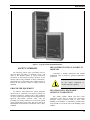
Figure 1 - Typical 37-inch MASTR III Stations
SAFETY SUMMARY
The following general safety precautions must be
observed during all phases of operation, service, and
repair of this product. Failure to comply with these
precautions or with specific warnings elsewhere in this
manual violates safety standards of design, manufacture,
and intended use of the product. M/A-COM assumes no
liability for the customer’s failure to comply with these
standards.
GROUND THE EQUIPMENT
To minimize shock hazard, the station equipment
cabinet must be connected to an electrical ground. The
equipment supplied is equipped with a three-conductor
AC power cord. The power cord must be plugged into an
approved three-contact electrical outlet with the
grounding wire firmly connected to an electrical ground
(safety ground) at the power outlet. The power cord meets
International Electrotechnical Commission (IEC) safety
standards.
REPLACEMENT OF PLUG-IN CIRCUIT
MODULES
Component or module replacement and internal
adjustments must be made by qualified maintenance
technicians.
Do Not replace components or
modules with power applied.
CAUTION
ELECTROSTATIC DISCHARGE SENSITIVE COMPONENTS
This station contains CMOS and other circuit
components, which may be damaged by electrostatic
discharge. Proper precaution must be taken when
handling circuit modules. As a minimum, grounded wrist
straps should be used at all times when handling circuit
modules.
11
LBI-38636S
DO NOT SUBSTITUTE PARTS OR
MODIFY PRODUCT
Because of the danger of introducing additional
hazards, do not install substitute parts or perform any
unauthorized modifications to the product.
INTRODUCTION
This manual describes the installation and
connections for a typical MASTR III station combination.
Information provided includes suggested locations and
installation of equipment and hardware, interconnection
and assembly diagrams, alignment instructions, and
troubleshooting suggestions.
The MASTR III cabinet normally includes the
Transmitter/Receiver Shelf, the Transmitter Power
Amplifier, and a Station Power Supply. The assemblies
are mounted in a 37-inch cabinet. Optional 69- inch or
two stacked 37-inch cabinets are available.
CABINET
The system is contained in a 37-inch cabinet with
improved ventilation for greater reliability. The cabinet
can also house optional equipment such as a Duplexer,
Charger, Gell Cell batteries, or Auxiliary Receiver.
STATION POWER SUPPLY
The Station Power Supply provides all necessary
power to run the station. It provides 13.2 volts at 33 amps
to the station from an AC source. The source voltage
depends on the particular area and power sources
available. The power supply is normally mounted beneath
the T/R Shelf.
UNPACKING EQUIPMENT
Unpack the station and carefully inspect each item. If
any damage has occurred to the equipment during
shipment, immediately file a claim with the freight
carrier. AC power adequate to meet system requirements,
environmental control, and digital or voice grade phone
lines must be available at the site prior to installation.
SITE PREPARATION AND
INSTALLATION
CABINET INSTALLATION
The MASTR III station cabinet is designed for
servicing from the front. However, the system may also
be serviced from the rear when adequate space is
available. The cabinet should be mounted on a level, solid
surface.
If rear servicing is desired, cabinets should be setup
with a minimum of 24-inches of clearance in the rear and
between cabinets or wall to permit ventilation and room
for the service-man to move between and behind the
cabinets.
If space is at a premium or if servicing is to be made
from the front only, then cabinets should be setup with a
minimum of 18-inches of clearance in the rear and 12inches between cabinets to permit ventilation. However,
access to the rear of the cabinets may still be necessary in
order to install or repair antenna or power cables.
Single and double stacked 37-inch cabinets must be
securely anchored to the floor according to the footprint
shown in Figure 2 and following single or double stacked
installation instructions.
TRANSMITTER/RECEIVER SHELF
Single 37-inch Cabinet Installation
The MASTR III Transmitter/Receiver (T/R) Shelf
contains the station control electronics for dc/tone remote,
re-mote/repeater, or repeater only applications. The
station control electronics consists of a Backplane board,
Power Module, System Module, and an Interface Board.
The back-plane also connects the RF Section which
consists of the Receiver Synthesizer Module, First IF
Module, Second IF Module, and the Transmit Synthesizer
Module.
The station provides for front and rear door servicing
or front door only servicing in tight space situations. The
front and rear of the station must be kept clear of
obstructions so that the serviceman can easily remove the
front and rear doors for servicing. Also, the front and rear
air vent louvers and rear cable outlets must be free of
obstructions.
TRANSMITTER POWER AMPLIFIER
The Transmitter Power Amplifier is mounted directly
behind the T/R Shelf. Cabling from the output of Power
Amplifier will depend on the system configuration.
12
LBI-38636S
serviceman can easily remove the front and rear doors for
servicing. Also, the front and rear air louvers and rear
cable outlets must be free of obstructions. Leave a
minimum of 12-inches of space on each side of the
cabinets to avoid obstructing the louver air vents. With
the bottom cabinet in position, secure it to the floor as
shown in Figure 2 with 1/2-inch bolts and anchors.
Remove the four plastic plugs in the top surface of the
bottom cabinet (by squeezing the plastic retaining barbs
together from the inside of the cabinet and pushing the
plug up and out).
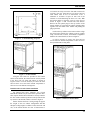
Figure 2 - 37 Inch Mounting Footprint
Position the top cabinet on the bottom cabinet. Align
the fixing holes and bolt the cabinets securely together
using 1/2 inch bolts, washers, and locknuts (supplied in
hardware kit 344A3450G7) as shown in Figure 4.
It will be necessary to remove the front and rear
covers and some internal components to allow access to
the top and bottom securing holes.
Figure 3 - 37-Inch Cabinet
Using the four holes are provided in the bottom
surface of the cabinet, the cabinet must be securely bolted
to the floor with 1/2" bolts and anchors as shown in
Figures 2 and 3. It will be necessary to remove the front
and rear door covers and some internal components to
allow access to the bottom securing holes.
Double Stacked 37-inch Cabinet installation
For limited floor space situations, two 37-inch
MASTR III cabinets may be stacked one upon the other.
This requires that the bottom cabinet be securely bolted to
the floor surface and the top cabinet securely bolted to the
top surface of the bottom cabinet, as shown in Figure 4.
Figure 4 - Stacked 37-Inch Cabinets
Ensure first that the floor is strong enough to support
the weight of the two cabinet configuration and that
adequate ceiling height is available. Ensure the front and
rear, of the station cabinets are clear of obstructions so
13
LBI-38636S
ELECTRICAL CONNECTIONS
AC Power
The station will be received with the power cord
bundled and stored in the bottom of the cabinet. Remove
the twist tie from the AC power cord, unravel and feed the
cord through one of the rear cable holes. It may be helpful
to remove the grommet from the hole before passing the
cord through and reinstalling it afterwards.
A separate 15 to 20 Ampere, 120 Vac, 60 Hertz
electrical circuit should be provided for the station. A 120
volt grounded AC outlet for the station should be located
within six feet of the lower rear of the cabinet. The power
cord for the 120 Vac Power Supply comes with a
grounded 120 Vac molded plug attached. Check the
electrical code to ensure the power outlet complies with
local ordinances.
TELEPHONE LINE CHARACTERISTICS
Telephone Lines
The type of telephone lines required for the
installation will depend on how the station is controlled
and if it is being used for simplex or duplex operation.
Generally, both 4-wire Audio and E & M Signaling
options are used to interface between the radio and carrier
systems. However, 2-wire Audio can be used in the twoway radio portion of the control system if hybrids are
installed to provide transition between the 2-wire and 4wire connections. Usually the E & M Signaling is
separated from the audio (separate line) in both 2-wire
and 4-wire installations.
If a 240 Vac, 60 Hz source is used for the station, an
external step-down transformer (similar to 19C307148P1)
must be used.
For 230 Vac, 50 Hz applications, the station power
supply is equipped with a power cord, less connector, to
permit connection to an acceptable electric circuit. A plug
meeting local electrical codes must be supplied by the
customer. Make sure the station power supply is
connected to an outlet having the same configuration as
the plug. No adapters should be used in this configuration.
The equipment should be connected to a good earth
ground using a ground wire of adequate size. A ground
stud is provided for a separate cabinet ground. Use No. 14
or larger wire (depending on local ordinances and system
requirements) for connecting the cabinet to a good
building ground. After the ground lead from the power
cable is connected to the building ground, check for
continuity between building ground and the cabinet.
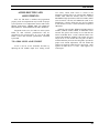
Microphone
The local microphone or utility handset may be
attached to the station through the MIC port on the front
of the T/R Shelf (Figure 6), the connections are shown in
Figure 5.
Antenna
The antenna cable may be routed through the top rear
or bottom rear of the cabinet directly to the appropriate
connector within the station, depending upon the
configuration.
14
Figure 5 - Microphone Connections
Types Of Voice Grade Lines
Telephone lines are normally obtained from a
communications common carrier ("telephone company"
for our purposes here). When a voice grade (as contrasted
to a "data line") telephone line is requested, there is no
way of knowing just what type of line will be received
from the phone company.
In addition, the telephone company may supply one
type of line first, and later change it to another type
without any notification to the user. One of the following
types of telephone line can be expected:
1. Wire lines with no amplifiers
2.
Wire lines with amplifiers added to compensate
for line loss
3.
Facilities derived from carrier (multiplex)
These lines have different operating characteristics,
and each must be treated differently. In large systems, all
three types of lines can be provided. In long haul
applications, a system can consist of two or three of these
types of lines in tandem (tied together end-to-end).
The first type is WIRE LINE WITH NO
AMPLIFIERS. These are the same lines that have been
used for years to control dc systems. These are the easiest
to work with since they include no problem-causing
electronic equipment. These lines are normally found in
LBI-38636S
less populated areas where the phone company has not yet
switched to carrier systems. These lines have a fixed
amount of loss, which varies with frequency, temperature,
from deterioration of splices, and from moisture getting
into the cables. When these cables get old, the phone
company sometimes applies DC current to improve the
joints and lower the line loss. In this case, the line is not
usable for DC control.
Normally, a +10 dBm test tone can be applied to
these lines. These lines do not normally include any type
of voice limiters.
The second type of line is a WIRE LINE WITH
AMPLIFIERS. These lines are normally supplied when
the loss of available lines is too high. An amplifier or
several amplifiers are added to the line to make up for the
loss.
One commonly used amplifier is the E-6 repeater.
This amplifier will pass DC current and they have been
used on DC lines for years. These amplifiers include
limiters, which start limiting at somewhere around 0 dBm
input to the amplifier. The limiters do not cause any real
problems on DC systems since only the voice peaks are
clipped. However, special care must be used when
applying them to tone remote control systems.
Each amplifier can be adjusted for up to 12 dB of
gain. If the loss is more than 12 dB, one or more
amplifiers may be added. The amplifier(s) can be placed
at any point in the line.
The third type of telephone line is a Derived Facility
using carrier equipment. Since this is the most
complicated, more care is required when connecting radio
equipment. This type of line will be available more often
in the future.
The telephone company supplies two wires at each
end of the circuit. Each two-wire end goes to some point
in the circuit where it is converted to a four-wire circuit
and then connected to the carrier equipment. A four-wire
circuit can be ordered if that is what is required. At the
other end, it is taken out of the carrier equipment and
converted back to the two-wire circuit. The carrier
equipment has a transmit path and a receive path. The
gain is adjustable each way.
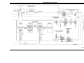
Figure 6 - T/R Shelf Connections
15
LBI-38636S
16
LBI-38636S
The telephone company wants to see a maximum threesecond level of -13 dBm at the carrier equipment as
measured on a modified Western Electric 3-type Noise
Measuring Set. The telephone equipment will limit the
audio if the signal is above -13 dBm at the carrier input.
This does not mean that the maximum that can be applied
into the two-wire end is -13 dBm. If the radio equipment
is a good distance from the carrier equipment, there will
be some line loss. If the loss is 5 dB, for instance, then -8
dBm could be applied into the two-wire end. Therefore,
the telephone company will have to be asked in each case
what level is allowed to be applied at the two-wire end.
If the telephone company checks and finds that too
much audio is being applied into the carrier equipment,
they will put a pad into the circuit to cut the audio down.
When the phone company is asked what levels can be
applied to the line, they will either provide a level in
Volume Units (VU) or test tone. VU is average voice,
which is generally considered to be 10 dB below test tone.
Test tone is a 1000 or 1004 Hz tone used to line up the
circuit. Test tone is normally given in dBm. If the radio
installer isn’t careful, he and the phone company will be
talking 10 dB apart. If the phone company says the limit
is 0 VU, use +10 dBm for the line-up.
The two wire ends of these lines are normally
designed to work with a 600 ohm impedance in and out.
The transmit and receive carrier equipment gains are set
up for 600 ohm terminations. If the line to the carrier
equipment is fairly long, the impedance at which at the
two-wire end is not very critical.
If the two-wire end is close to the carrier equipment,
however, then the impedance is critical. If the impedance
is not 600 ohms, it can cause the gain of the carrier
equipment to go up or down. In some cases, feedBack
(oscillations) from the receive path to the transmit path
will be present. A common problem that causes
oscillations in the carrier equipment is gain change,
whether from misalignment or other reasons.
American Telephone and Telegraph Company has
published a reference for Voice Grade Lines entitled,
"Private Line Interconnections, Voice Applications"
(Publication Number 43201). It covers several types of
private line interfaces. There is no publication that covers
radio control alone. However, there are several
parameters provided in the publication that are important
to note.
The 1000 Hz loss design objective is 0 to 10 dB. If
the loss is not specified, there will be a loss of 10 dB at
1000 Hz in most cases. The phone company allows itself
a SHORT-TERM fluctuation of 3 dB and a LONGTERM variation of 4 dB. If a 10 dB loss line at 1000 Hz
is specified, up to 14 dB loss can be expected, and the
phone company would still be within their design limits.
The loss between 500 and 2500 Hz can be +2 dB and
-8 dB relative to 1000 Hz loss. Note that the phone man
may refer to this as -2 and +8 in the telephone company
way of talking. The loss between 300 and 3000 Hz can be
+3 dB to -12 dB relative to the 1000 Hz loss. This says
that if there is a line with 10 dB of loss at 1000 Hz, a loss
of as much as 18 dB at 2500 Hz, and 22 dB of loss at
3000 Hz can be expected. A loss 4 dB of long-term
variation should be added to this.
Noise on this type of line is measured at each end
with a Western Electric 3-type Noise Meter. The
allowable level of a line from 0 to 50 miles is 31 dBrnC,
and for a line from 51 to 100 miles is 34 dBrnC. If this
type meter is not available, an AC- VTVM can be used. If
there is a noise reading of -50 dBm or less, generally this
is considered an acceptable circuit.
Tone Remote Control Systems
In contrast with DC systems, where audio level
setting is not as critical, it is important that levels in tone
applications be set properly. Failure to do so results in the
control function not working properly. For example, after
the installation when the user has gained a little
experience, the user may find that they are not always
picking up the function selected. A little extra time spent
at the installation will save many problems of this type
later.
This equipment is designed so that the tone sequence
consists of either two or three parts. The first part is the
"Secur-it" tone (2175 Hz) which is sent at the highest
level for approximately 125 milliseconds. This is
followed by the "Function" tone which is sent at a level
10 dB lower for approximately 40 ms. In the case of a
transmit function, the "Function" tone is followed by
2175 Hz "Hold" tone at a level 30 dB down from the
"Secur-it" tone burst (therefore, it is 20 dB down from the
"Function" tone burst). This tone continues for the
duration of the transmit function. The average voice (0
VU) is sent at the same level as the "Function" tone,
therefore, the test tone for the voice is sent at the same
level as the "Secur-it" tone.
The "Secur-it" tone must arrive at the base station at
no less than -20 dBm. The transmit "Hold" tone must
arrive at the base station at no less than -50 dBm. The test
tone for the voice must arrive at the base station at no less
than -20 dBm. Therefore, the limits of system operation
are usually established by only three things:
1. The maximum level at 2175 Hz that the phone
company will allow to be sent from the most
distant point in the system. Normally this will
not be higher than 0 dBm. In some cases it can
even be less, or on rare occasions it can be +5 or
+10 dBm.
17
LBI-38636S
2.
The loss of the circuit at 2175 Hz. Do not forget
the long-term variation of up to 4 dB more.
3.
The requirement that the "Secur-it" burst must
arrive at the base station at no less than -20 dBm.
Normally, most systems will not crowd these limits.
However, if the result is a few dB short, consider adding
C-1 conditioning (at an added cost). Resist the natural
desire to just turn up the tone sending level as this will
cause improper system operation.
Increasing the level will cause the "Secur-it" tone
burst to go into limiting in the phone company equipment.
The limited tone causes the "Secur-it" tone filter in the
base station to ring. This will result in picking up or
dropping out functions, which were not selected. NEVER
allow the "Se-cur-it" tone to be in limiting.
There is an easy way to check and see if the "Securit" tone is in limiting. With the phone lines connected to
the equipment at both ends connect an AC voltmeter
across the phone line at the base station. Arrange to send a
burst of "Secur-it" tone long enough to measure the
incoming level on the AC voltmeter. Then arrange to send
a burst of 1950 Hz "Function" tone long enough to
measure the incoming level on the AC voltmeter. If the
1950 Hz tone does not arrive 10 dB (1 dB) less than the
"Secur-it" tone, then the "Secur-it" tone is in limiting. It
will become necessary to lower the sending level at the
remote controller until it is below limiting.
If the audio is high enough to cause the telephone
equipment to go into limiting, it will cause amplitude
distortion. On a high loss line the amplitude distortion
will cause the "Hold" tone (2175 Hz) to vary and the
transmitter to drop out.
On remote systems using tone control, care must be
used when connecting two telephone lines in tandem. For
example, for a base station and two remotes, a phone line
is ordered to connect the station to the first remote, and a
second line to connect the second remote to the first
remote. The loss of each line is now added together and
the tones from the second remote can not operate the base
station. The installer can either specify a low loss on each
line, or run each line directly to the base station.
A check with the phone company can determine
which approach is the least expensive over a period of
time; i. e., an analysis of non-recurring costs versus
recurring costs over the expected length of time the circuit
will be used.
Voting System Considerations
A voting system uses a continuous 1950 Hz tone on
the telephone line when the receiver is squelched. This
voting tone is normally sent from the station to the voting
18
selector 3 dB lower than the 1000 Hz test tone level. Most
telephone lines have a frequency response which
attenuates the 1950 Hz tone with respect to a 1000 Hz test
tone, therefore care should be taken to ensure that the
correct levels are received at the voting selector.
If the telephone company will not allow a continuous
tone as high as -8 dBm to be sent, then a lower loss circuit
should be requested or C-1 conditioning added.
When ordering phone lines for a voting system, if
possible, all lines should be of the same type. Different
telephone line responses will cause the voter to prefer one
signal over others.
It is improper system design to have the received
signal selection biased by a "poorer" telephone circuit.
Many telephone companies will add pads to build out the
lines. If this is considered when the lines are ordered, it
should not be difficult to build all of the lines out to have
the same frequency response.
Ordering Voice Grade Telephone Lines
If a standard voice grade circuit is ordered, and the loss is
not specified, the following will normally result:
1. Loss at 1000 Hz will be 5 to 10 dB; normally 10
dB
2.
Long-term variation 4 dB
3.
Amplitude distortion (frequency response)
Referenced to 1000 Hz; + = more loss 300 to
3000 Hz: -3 to +12 dB 500 to 2500 Hz: -2 to + 8
dB
4.
Noise: 31 dBrnC maximum
5.
Frequency translation error: 5 Hz
6.
Normal impedance: 600 ohms
7.
Maximum permitted signal into the line: -6 dBm
to -13 dBm in-band three second average (the
level arriving at the carrier equipment cannot be
more than -13 dBm).
By adding C-1 conditioning, the loss changes to:
Amplitude distortion (frequency response) Referenced to
1000 Hz; higher frequency = more loss 300 to 2700 Hz: 2 to +6 dB 1000 to 2400 Hz: -1 to +3 dB
One added advantage to C-1 conditioning is that the
voice quality will be improved by boosting the high
frequency components.
LBI-38636S
Telephone Company Ordering Information
Four-Wire Operation
When ordering a telephone line, the following must
be considered:
1. Type of circuit:
Voice grade, 2-wire termination, for radio
control, and tone remote system - send/
receive; voting system - receive only.
For examples, refer to Methods 3 and 4 in Table 1,
and the associated illustrations showing the different
methods (Figures 10 & 11). Jumpers should be installed
on P104-2 to P104-3 and P105-2 to P105-3 on the
Interface Board.
2.
DC continuity not required
3.
Impedance: 600 ohms 20%
4.
Line Loss:
Tone remote system:
Sends 2175 Hz tone for 125 milliseconds, and
it must arrive at the base station at no less than
-20 dBm including long-term variation.
Average voice is 10 dB below the 2175 Hz
tone burst.
Voting system:
Sends a continuous 1950 Hz tone when the
receiver is squelched, and it must arrive at the
voting selector at no less than -30 dBm
including the long-term variation.
5.
C-1 conditioning if necessary. (If two phone
lines are to be tied in tandem, it is usually proper
to specify C-1 conditioning.)
6.
If more than one phone line is to be used, a block
diagram showing locations and type of
equipment to be used should be provided the
telephone company.
TELEPHONE LINE INSTALLATION
DC Remote Installation
Two-Wire Operation
For two-wire operation, connect the pair to TB101-3
and -4. If the remote control unit at the other end is an
RCN 1000, use J3-3 (red) and -4 (green). Refer to
Methods 1 and 2 in Table 1 and associated illustration for
examples (Figures 8 & 9). Jumpers should be placed on
P104-1 to P104-2 and P105-1 to P105-2 on the Interface
Board. Figures 15 & 17 shows the location of Interface
Board connectors and jumpers.
NOTE
Polarity must be maintained, if the
metallic control pair is being used for DC
control.
E & M Signaling
E & M lead signaling systems derive their name from
certain historical designations of the signaling leads on
circuit drawings. An "M" lead is associated with the
transMit function or Mouth, while the "E" lead is
associated with the recEive function or Ear. In two-way
radio systems with remote control, E & M Signaling can
be the only type of control offered by the available carrier
circuits.
Generally, both 4-Wire Audio and E & M Signaling
options are used to interface between the radio and carrier
systems. However, 2-Wire Audio can be used in the twoway radio portion of the control system if hybrids are
installed to provide transition between the 2-Wire and 4Wire connections. Usually the E & M Signaling is
separated from the audio (separate line) in both 2-Wire
and 4-Wire installations.
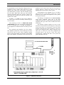
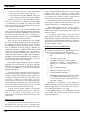
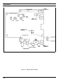
Figure 7 illustrates a typical interface between a twoway radio system and a multiplex/microwave system. The
Remote Control Console and Base Station are equipped
with the E & M Signaling Option and the 4-Wire Audio
Option. The console provides a regulated -48 Vdc output
(or -24 Vdc with minor modifications) to the "M" lead
when the TRANSMIT switch is pressed. This -48 Vdc
activates a tone encoder (usually 3825 Hz) in the
multiplex rack. The tone encoder modulates the carrier
frequency, which is transmitted over the microwave link.
At the station end of the microwave link, the signal is
demodulated and the 3825 Hz tone operates a tone
decoder in the multiplex rack. The output of the decoder
results in a contact closure, which applies +48 Vdc (or
+24 Vdc) to the control shelf. This voltage should be
connected between TB101-1 and TB101-6 on the
Interface board. Jumpers on P104 and P105 of the
Interface Board should also be removed. If +48 Vdc is
being used, resistors R116 and R118 on the Interface
Board should also be removed.
When the system is configured in this manner,
approximately +8 milliamperes flows through the DC
control decode circuitry on the backplane. This will cause
the T/R Shelf to decode a +6mA control current to key the
transmitter and route line audio to the transmitter.
19
LBI-38636S
Tone Remote Installation
Four Wire Tone Remote
Jumpers P104 and P105 located on the Interface
Board are not required and should be removed. Refer to
the
sections
on
TELEPHONE
LINE
CHARACTERISTICS and LEVEL ADJUSTMENTS for
additional installation information. Line connections are
made to TB101 or J101 on the T/R Shelf’s Interface
Board. TB101 and J101 are connected together and each
has the same pin out.
When the control shelf is used with a four wire tone
re-mote/console, the remote control transmit pair (which
modulates the transmitter) should be connected to TB1012 and -5. The remote control receive pair (which listens to
the receiver) should be connected to TB101-3 and TB1014.
Two Wire Tone Remote
When the control shelf is used with a two wire tone
re-mote/console, the remote control pair should be
connected to TB101-3 and TB101-4.
20
Connections
Telephone line connections may be made on the
terminal block (TB101) or with an RJ11 connector to
J101. The telephone line cable may be routed through the
top rear or bottom rear of the cabinet (Assembly
Diagram). The telephone line connections are shown in
Figure 12.
LBI-38636S
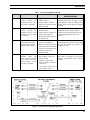
Table 1 - Wire Line Installation Methods
METHOD
DESCRIPTION
PROCEDURE
ADVANTAGES OR
DISADVANTAGES
1
Single metallic pair (the a. Connect the metallic pair to
control currents are
TB101-3 and -4.
simplexed to line, a two b. Jumper P105-1 to P105-2,
wire cable is required).
and P104-1 to P104-2 on the
Interface Board.
Economical: Dependable where earth
ground currents may be large or good
earth grounds cannot be obtained. The
keying clicks will be heard on parallel
remotes.
2
Single metallic pair (the
control currents are
simplexed line to earth
ground, a two wire cable
is required).
a. Connect the metallic pair to
TB101-3 and -4.
Economical: Minimizes keying clicks in
paralleled remotes but large ground
currents may result in interference with
control function if located near substations.
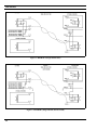
One voice grade circuit
for bi-directional audio
and the other a metallic
pair of control voltages.
a.
3
b. Jumper P105-1 to P105-2 to
P104-1 on the Interface
Board and connect TB101-6
to earth ground.
Connect audio pair
TB101-3 and TB101-4.
to
b. Remove jumpers from P104
and P105 on Interface Board.
Provides excellent performance by
eliminating keying clicks and providing
no path for ground loop current, but
requires two pair.
c. Connect control metallic pair
to TB101-1 and -6 on
Interface Board.
4
Single metallic pair for
transmit
audio
and
control Currents. Single
voice grade circuit for
receive audio. A four
wire line is required.
a. Connect the transmit metallic
pair to TB101-2 and -5 on
Interface Board.
b. Connect a jumper from
P104-3 to P104-2, and P1053 to P105-2.
Provides full duplex operation in which
the remote can operate in receive and
transmit simultaneously. But, requires
two pair.
c. Connect the remote receive
pair to TB101-3 and -4
Figure 7 - Typical E & M Signaling Application
21
LBI-38636S
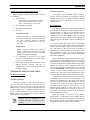
Figure 8 - METHOD 1 (Single Metallic Pair)
Figure 9 - METHOD 2 (Single Metallic, Earth Ground)
22
LBI-38636S
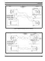
Figure 10 - METHOD 3 (Metallic Control Pair, Audio Pair)
Figure 11 - METHOD 4 (Full Duplex Metallic TX Pair)
23
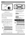
LBI-38636S
manufactured. Making your own requires only
three wire connections (Figure 13).
DB9
DB25
Pin 2
Pin 2
Pin 3
Pin 3
Pin 5
Pin 7
Figure 13 - 3-Wire Adapter
4.
Figure 12 - Telephone Line Connections
STATION SETUP
The MASTR III station comes pre-programmed and
ready to install, the only adjustments needed are the
required Line Output Level, the Line Input Level
necessary to produce Standard Deviation, and the Line
Cancellation for 2-wire Tone Remote Orientation. These
adjustments can be made using the PC Programming
option TQ-3353, or Utility PC software TQ-0619 with the
Utility Handset SPK9024.
If the system requires control by a remote unit,
the following interconnection must be made.
Connect the wires from the remote unit to the
six-pin terminal block (TB101). Use the
following information when making
connections:
TB101, Pins 3,4 - Line Input/Output for 2-wire
DC and Tone control.
or
Line Output for 4-wire DC and Tone control.
TB101, Pins 2,5 - Line Input for 4-wire DC and
Tone control.
TB101, Pins 1,6 - Line Inputs for E & M
signaling, DC Remote Control.
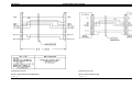
SETUP PROCEDURE
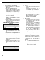
Table 2 - DC Remote Control
Use the following procedures when setting up the
station using a Personal Computer (PC). If the Utility
Handset is plugged into the MIC connector, it must be
removed prior to resetting the system and using the PC
Programming software. Levels may be adjusted using the
MASTRUTL program supplied with the PC
Programming package. A RESET (on the Power Module)
should be initiated before programming starts.
1.
Ensure proper connections are made to receive
and transmit antenna(s). See interconnect
diagram.
2.
Plug the power cord from the base station into a
120 Vac, 60 Hz power source.
NOTE
3.
NOTE
Connect the PC computer’s serial COM port and
the DATA PORT on the front of the T/R Shelf
using the TQ-3356 Interconnect cable
(19B801348P2).
P104
P105
COMMENTS
1 to 2
2 to 3
1 to 2
2 to 3
Both jumpers back
Both jumpers forward
P104, Pin 1 and P105, Pin 1 are on the far
side of the connector if you are facing the
front of the base station. Refer to Figures
16 thru 18.
5.
The SQUELCH and VOLUME adjustments
should be made for proper operation. Unsquelch
the receiver by turning the SQUELCH
adjustment counter-clockwise. (If your base
station has Channel Guard, also activate the CG
switch.) Verify that unsquelched noise is going
to the speaker by increasing the VOLUME
(clockwise). Adjust the SQUELCH pot for
critical squelch (squelch just closes).
6.
Following the initial setup, the MIC port may be
used for one of the following purposes:
a. Connecting the local microphone
equipped with a modular connector.
If a 230 volt, 50 Hz source is used,
connect the locally required plug.
If the computer has a 25-pin connector instead of
a 9-pin connector, an adapter must be installed.
The adapter may be either purchased or locally
24
2-wire
4-wire
b.
Connecting the multi-purpose Utility
Handset.
LBI-38636S
Table 3 - Station Connectors
CONFIGURATION
Simplex (T/R Relay)
Duplex (Internal Duplexer)
Duplex (External Duplexer)
STATION TERMINATING
CONNECTOR
N-Type Female
N-Type Female
BNC Female (Rx)
N-Type Female (Tx)
LOCATION
Antenna Switch
Duplexer
T/R Shelf
Low Pass Filter
TO ENSURE THAT YOUR EXPOSURE TO RF ELECTROMAGNETIC ENERGY IS
WITHIN THE FCC ALLOWABLE LIMITS FOR OCCUPATIONAL USE, ALWAYS
ADHERE TO THE FOLLOWING GUIDELINES:
CAUTION
DO NOT operate the basestation with an antenna that would cause an ERP in excess of that
allowable by the FCC.
Figure 14 - Antenna Installation
25
LBI-38636S
Table 4 - Normal System Deviation
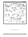
ALIGNMENT PROCEDURE
Alignment of the MASTR III base station was
performed prior to shipment. The factory assumed the
following characteristics:
1. There is no loss or gain for repeated audio
deviation.
2.
3.
If a remote exists, it is connected to the base
station through a telephone line with 10 dB of
loss.
The base station drives the line output at -10
dBm with nominal receive deviation.
The base station should deliver –10 dBm to the line
with a signal applied with 3kHz deviation. A –10 dBm
audio signal applied to the Station Line In should result in
transmitter deviation of 3 kHz.
These values may be altered by following one of the
alignment procedures as provided. For minor adjustments
you may want to adjust only one or two digital
potentiometers or leave the setting as set. In any case, it is
important to carefully examine the ALIGNMENT
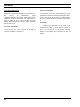
DIAGRAM (Figure 15) which follows:
NOTE
It is a good idea to record the
potentiometer settings on paper, until
you’re familiar with all the digital
potentiometer setting tools.
Test Equipment Required
The following test equipment is required to align the
MASTR III base station:
• Audio Oscillator
•
AC Voltmeter
•
RF Signal Generator
•
Deviation Monitor
•
Handset or PC Computer (with diagnostic utility
TQ-0619)
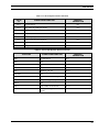
System Deviation
Standard (25 Hz kHz Bandwidth
NPSPAC
Narrow (12.5 kHz Bandwidth)
2.
3.0 kHz
2.4 kHz
1.5 kHz
Channel Guard (GC)
• If the station is not programmed for CG, set
CG Pot to 0.
For a station programmed with CG encode follow
these steps:
• Execute a REMOTE PTT on the System
Module by flipping the REM PTT switch
on the front panel.
• Adjust the CG Pot as needed (Table 5).
Table 5 - Channel Guard Deviation
Channel Guard
Deviation
Standard (25 Hz kHz Bandwidth
NPSPAC
Narrow (12.5 kHz Bandwidth)
3.
0.750 kHz
0.600 kHz
0.500 kHz
•
Repeat for each channel.
•
Disable CG decode and encode for the
remainder of the station alignment.
TX Limiter
• Preset the following digital potentiometer
values:
Repeater Gain (RG) 1023
Compressor Threshold (CT) 5000
Compressor Gain (CP) 1023
DSP Line In (DLI) 100
• Apply a 1000 Hz tone, at the maximum
system audio level, across the 600 ohm load
termination to the Line Input.
This level is the secur-it level, and is
usually 0 dBm across 600 ohms, (775
mVrms). The "maximum system audio
level" is the absolute highest signal level
that will be present on the line and must be
10 dB higher than average voice audio level.
Procedure
Terminate both the Line Input (T101-3,4) and Line
Output (T101-2,5) with a 600 ohm load. This step must be
completed for all parts of the alignment to ensure proper
level setting (Table 4).
1. Line In
• Set Line Input digital potentiometer (Pot) LI
to 0.
26
•
Execute a REMOTE PTT on the System
Module by flipping the REM PTT switch
on the front panel.
•
Adjust the TX Pot to maximum system
deviation (Table 6).
LBI-38636S
4. Repeater Gain
• If the station is not a repeater, leave the
Repeater Gain pot RG at 1023.
• If the station is a repeater, apply an "on
channel" RF signal modulated with a 1000
Hz tone at 60% of system deviation to the
receiver.
• Adjust RG pot for 60% of system deviation
(Table 8).
Table 6 - System Deviation
System
Deviation
Standard (25 Hz kHz Bandwidth
NPSPAC
Narrow (12.5 kHz Bandwidth)
•
3.75 kHz
3.0 kHz
1.75 kHz
Remove the 1000 Hz tone from the Line
Input and the REMOTE PTT.
Repeat this step for every channel.
•
Figure 15 - MASTR III System Module Pot Alignment
Table 7 - Digital Potentiometer Settings
HANDSET
NUMBER
POT PAGE
(Note 3)
HANDSET
DISPLAY
DEFAULT
VALUES
LO
POT
DC
POT
LI
POT
DLI
POT
CP
POT
CT
POT
RG
POT
TX
POT
CG
POT
Line
Out
DSP Line
Cancellations
Line
In
DSP
Line In
DSP
Compress
or
Gain
Comp
Threshold
Repeater
Gain
Transmit
Channel
Guard
1
5
3
6
7
2
2
2
1
P_1
P_1
P_1
P_1
P_1
P_2
P_3
P_1
P_1
P LO
P DC
P LI
P DI
CP
CT
RG
P TX
P CG
45
75 (2W)
0 (4W)
0
34 (2W)
28 (4W)
1023
1890
1023
127
150*
123
0*
*no Channel Guard
NOTES: 1) VOL/SQ sensitivity: 1000 mV rms = 3 kHz peak deviation (System Module, Pin, B2)
2) MOD sensitivity: 1000 mV rms = 5 kHz peak deviation (System Module, Pin, C3)
3) Refer to Handset manual, LBI-38599, for instructions on page selection.
Table 8 - 60% of System Deviation
60% of System
Deviation
Standard (25 Hz kHz Bandwidth
NPSPAC
Narrow (12.5 kHz Bandwidth)
•
Remove the signal from the receiver.
3.0 kHz
2.4 kHz
1.5 kHz
27
LBI-38636S
5.
Line Input Sensitivity and Compression
• If not a remote station, set the DSP Line In
DLI Pot to 0.
• If a remote station, do the following:
•
•
Apply a 1 kHz tone at the average voice
audio level across 600 ohms to the line
input. (This level is the function tone level,
and is usually -10 dBm across 600 ohms, or
245 mVrms. This level MUST be 10 dBm
below the "maximum system audio level"
even if your actual secur-it tone and function
tone are at the same level.)
Execute a REMOTE PTT on the System
Module by flipping the REM PTT switch on
the front panel.
Adjust the DSP Line In DLI Pot for 60% of
maximum system deviation if operating with
compression. (Table 9).
6.
Line Out
• If not a remote station, set the Line Out LO
Pot to 0.
• If the station is a remote station, apply an
"on Channel" RF signal modulated with a 1
kHz tone at 60% of system deviation to the
receiver. (60% of system deviation is
usually 3 kHz.)
• Adjust the Line Out LO Pot for the desired
output level as measured across 600 ohms.
The line out level must never rise above 7
dBm, as measured across 600 ohms.
• Re-enable Channel Guard decode.
7.
DSP cancellation
• If the station is a 4 wire station, set the DSP
Line Cancellation DC Pot to 0. If the station
is 2 wire, do the following:
Table 9 - Deviation For Setting Line In Pot With
Compression
•
Apply a RF signal to the receiver modulated
by a 1000 Hz tone at 60% of rated system
deviation and monitor the remote’s Line
Out. The level of the Line Out should be
between +7 dBm and -19 dBm.
•
Put the System module on an extender card
and meter TP1 on the DSP board. On
stations with Group 6 or later T/R shelf, the
TPI signal can be observed at J5-28A on the
backplane. An oscilloscope may be more
helpful than an analog meter. Adjust the
DSP Cancellation DC Pot for a null at TP1.
Deviation For
Setting Line In Pot
With Compression
Standard (25 Hz kHz Bandwidth
NPSPAC
Narrow (12.5 kHz Bandwidth)
•
•
•
•
2.8 kHz
2.2 kHz
1.4 kHz
If no compression is desired, set DLI pot to
60% of maximum system deviation (Table
8).
If compression is desired, adjust the DLI Pot
for 60% of maximum system deviation
(Table 8).
Increase the audio input level to the
maximum system audio level. (This level is
the secur-it level, and is usually 0 dBm
across 600 ohms, or 775 mVrms. This level
must be 10 dB higher than the average voice
audio level.)
Adjust the Compressor Threshold CT pot for
desired compression deviation level (Table
10).
Table 10 - Deviation For Setting Compressor
Threshold Pot
Deviation For
Setting Line In Pot
With Compression
Standard (25 Hz kHz Bandwidth
NPSPAC
Narrow (12.5 kHz Bandwidth)
28
4.0 kHz
3.2 kHz
2.0 kHz
8.
Tone Remote timing
You must have PC Programmer for base stations,
version 9.0 or later, to affect the timing of Tone
Remote Decoding.
If you have two wire tone remote, do the
following:
• In the timing screen of the option screen,
ENABLE Timed Tone Remote. The
default values of 100ms and 150ms will
appear for Secur-it minimum time and
Secur-it maximum time. Change these
values as your system requires.
LBI-38636S
AUDIO ROUTING AND
ADJUSTMENTS
Once the T/R Shelf is installed and programmed
properly, audio level adjustments may be made for proper
system operation. Level adjustments must be made with a
handset (LBI-38599). THERE ARE NO MANUAL
MECHANICAL ADJUSTMENTS IN THE T/R SHELF.
Integrated circuits (IC's) U35 and U36 on the System
Board are dual electronic potentiometers that are
controlled by the microprocessor. IC U15 on the DSP
Board is also a dual electronic potentiometer controlled
by the DSP.
TX AUDIO LEVEL ADJUSTMENT
U36-0 is used to set the transmitter deviation by
adjusting the TX AUDIO output level. Analog switch
U15 selects, which audio source is routed to the
transmitter. Possible sources are LOCAL MIC, REPEAT
AUDIO, DSP LINE/TX AUDIO, DSP TX AUDIO,
EXTERNAL High Speed Data, LINE IN AUDIO, OPEN
(used for Morse code ID), and GROUND (used for no
transmission. A battery alarm tone may also be summed
in with whichever source is selected with the exception of
GROUND.
Normally, LOCAL MIC, REPEAT AUDIO, DSP TX
AUDIO, LINE IN AUDIO, OPEN, or GROUND will be
selected. The gains in the circuitry are set such that 100
mVrms in the MIC HI or 1 Vrms (3 kHz deviation) in on
VOL/SQ HI (REPEAT AUDIO) will produce the same
out-put level on TX AUDIO HI. The gains for Morse
code ID and battery alarm are also designed to provide the
proper levels without adjustments. The TX AUDIO HI
output level should be adjusted with a 100 mVrms, 1 kHz
signal in on MIC HI or a 1 Vrms, 1 kHz signal in on
VOL/SQ HI.
29
LBI-38636S
30
LBI-38636S
31
LBI-38636S
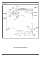
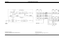
Figure 16 - T/R Shelf Interface Board
32
LBI-38636S
33
LBI-38636S
34
LBI-38636S
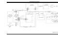
Figure 17 - T/R Shelf Interface Board (Rev. A)
35
LBI-38636S
36
LBI-38636S
37
LBI-38636S
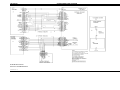
Figure 18 - T/R Shelf Interface Board ( Rev. C)
38
LBI-38636N
REMOTE CONTROLLER TO STATION
CONTROL PANEL ADJUSTMENTS
Although audio levels should be considered on a
system basis, it is appropriate to set the levels of the
remote controller and the control station panel by
themselves with reference to the levels required by the
transmission path and then connect the controller(s) and
station to the path. The transmission path, if it is more
than just a simple twisted pair, is usually set up with a
"test tone". The "average voice" level is defined as being
a certain number of decibels below the test tone. The test
tone is normally the maximum level that can be sent
through the path without clipping or being regulated.
Although there is no definite agreement on the difference
between the test tone and average voice levels, 10 dB is
an appropriate level.
In order to align the RCN 1000 Remote Controller
and T/R Shelf properly, it will be necessary to have some
information on the transmission path. This will help to
determine the levels at each end required by the system.
Specifications needed include:
1. Loss at 1 kHz
2.
Test tone or maximum level
3.
Average voice level (if defined)
4.
Loss at 2175 Hz (if tone remote)
The DSP Board performs tone detection in a tone
remote installation. The "Secur-it" tone Decoder on this
board has a dynamic range of approximately 9 dB. The
system must be set up such that the "Secur-it" tones from
all remotes in the system arrive at the T/R Shelf within
this 9 dB window.
LINE OUT LEVEL ADJUSTMENT
U36-1 is used to set the line out level. Analog switch
U14 selects which audio source is routed to the line.
Possible sources are LOCAL MIC, VOL/SQ, auxiliary
receiver audio, auxiliary receiver audio summed with
VOL/SQ (simultaneous monitor), DSP LINE/TX
AUDIO, MODEM LINE data, OPEN (used for battery
alarm), GROUND (used for no transmission, and LINE
IN audio (used for four wire loop around). A battery
alarm tone and/or VG ALERT tone may also be summed
in with whichever source is selected with the exception of
GROUND. Typically LOCAL MIC, VOL/SQ, DSP
LINE/TX AUDIO, OPEN, GROUND, or LINE IN
AUDIO will be selected.
The gains in the circuitry are set such that 100
mVrms in on MIC HI or 1 Vrms (3 kHz deviation) in on
VOL/SQ HI (REPEAT AUDIO) will produce the same
line output level. The gains for VG ALERT tone and
39
battery alarm are also designed to provide the proper
levels without adjustments. The LINE output level should
be adjusted with a 100 mVrms, 1 kHz signal in on MIC
HI or a 1 Vrms, 1 kHz signal in on VOL/SQ HI.
LINE IN LEVEL ADJUSTMENT
Typically, the TX AUDIO and LINE OUT levels
should be adjusted prior to adjusting the LINE IN level.
DSP TX AUDIO and DSP LINE/TX AUDIO are
typically line audio or VOL/SQ HI audio that has been
processed by the DSP Board.
A DSP Board is always present, this DSP processed
line in audio will normally be selected by analog switches
U14 (DSP LINE/TX AUDIO to line out) and U15 (DSP
TX AUDIO to transmit audio) on the System Module
when line in audio is selected. The level for DSP TX
AUDIO and DSP LINE/TX AUDIO must be adjusted on
the DSP Board.
DSP LEVEL ADJUSTMENTS
The LINE IN level into the DSP must be adjusted
using U15-0 (DSP line cancellation level) and U15-1
(DSP line input level) located on the DSP Board. If twowire audio is used then both electronic pots must be
adjusted. If four-wire audio is used then only U15-1 needs
to be adjusted.
For two wire installations the DSP line cancellation
level pot (U15-0) is used to remove what the T/R Shelf is
transmitting on the line. While the T/R Shelf is
transmitting received audio down the line, the line
cancellation pot should be adjusted to minimize the signal
level at TP1 on the DSP Board. This leaves only what is
received from the remote. This signal is then level
adjusted using the DSP line input level adjust pot (U15-1)
and input into the DSP.
NOTE
System modules 19D902590G2, G3, &
G4 must have their cover removed to gain
access to TP1 on the DSP board. Modules
G6 & G7 have TP1 extended to the board
edge connector and may be metered on
the MASTR III backplane at J5, Pin 28A.
If four wire audio is used, the DSP line cancellation
pot must be set to zero.
The DSP also performs a compressor function on its
line input. The threshold for this compressor must be
adjusted as well. The line level should be adjusted on the
DSP Board prior to setting the compressor threshold.
LBI-38636S
REPEATER PANEL INSTALLATION
CSI Model 32 Repeater Panel
Use the following information in Table 11 to
configure the MASTR III base station when installing the
CSI-32 Repeater Panel.
1. Cut the PWB pattern at JP-1 on the T/R Shelf’s
backplane 19D902948.
2.
Make the following connections between the
base station and the repeater panel. Connectors
P2, P3, and P5 are located on the backplane.
Connection to the repeater panel is made at J3,
the rear panel DB9 subminiature "D" type
connector.
NOTE
Zetron 38A Repeater Panel
Use the following information in Table 12 to
configure the MASTR III base station when installing the
Zetron 38A Repeater Panel.
1. Cut the PWB pattern at JP-1 on the T/R Shelf’s
backplane 19D902948.
2.
Make the following connections between the
base station and the repeater panel. Connectors
P2, P3, and P5 are located on the backplane.
Connection to the repeater panel is made at the
15 pin connector on the rear panel.
3.
Program the base station using the standard PC
programming software. For proper operation, the
station firmware must be 344A3307G12 (Group
12) or higher (MASTR III System Board - U4).
Special Conditions for MUX and Carrier:
1.
Add a pad of approximately 15 dB
in the connection between the
RCN output and the MUX input.
It is common for the MUX input to
have a test tone level of -16 dB and
an average voice level of -29 dB.
2.
Add a pad of approximately 15 dB
in the connection between the
Station Control panel output and
the MUX input.
NOTE
3.
Program the base station using the standard PC
programming software. For proper operation, the
station firmware must be 344A3307G12 (Group
12) or higher (MASTR III System Board - U4).
Program the following parameters:
a. Repeater (Single Channel only)
4.
b.
Repeater Panel (Community Repeater)
option
c.
RF Duplex
d.
No CG Encode/Decode
e.
No CCT or DODT Timers
f.
Remote Programming optional
Set the Repeat RF Modulation and Subaudible
Tone (CG) Modulation levels by adjusting the
Zetron 38A Repeater Panel Audio Output and
CTCSS Output potentiometers or the MASTR III
station’s TX Audio or CG digital potentiometers.
Use the CG pot (CTCSS pot for CSI-32) to adjust
the Subaudible Tone Modulation level and the TX
AUDIO pot (Audio Output pot for CSI-32) to
adjust the Normal Speech Modulation.
40
It may be necessary to decrease the value
of R5 (or short across) on the CSI
Repeater Panel to obtain the desired
Subaudible Tone Modulation level.
Program the following parameters:
a. Repeater (Single Channel only)
b. Repeater Panel (Community Repeater)
option
c. RF Duplex
d. No CG Encode/Decode
e. No CCT or DODT Timers
f. Remote Programming option
4.
Set the Repeat RF Modulation and Subaudible
Tone (CG) Modulation levels by adjusting the
Zetron 38A Repeater Panel Audio Output and
CTCSS Output potentiometers or the MASTR III
station’s TX Audio or CG digital potentiometers.
Use the CG pot (CTCSS pot for Zetron 38A) to
adjust the Subaudible Tone Modulation level and
the TX AUDIO pot (Audio Output pot for Zetron
38A) to adjust the Normal Speech Modulation.
LBI-38636S
Table 11 - CSI-32 Repeater Panel Connections
CSI-32
J3
MASTR III
CONNECTION
SIGNAL NAME FUNCTION
Pin 1
A+/(DC Power)
P5.1
Pin 2
SYS_VOL \SQ_HI/Repeat Audio)
P5.8
Pin 3
RCVR_VOL\SQ_HI/ (Demodulated Audio)
P2.5
Pin 4
N/C
Pin 5
REPEAT_PTT_IN
P2.13
Pin 6
CAS/(Carrier Activated Squelch)
P3.5
DGND/(Power Ground)
P2.2
EXT_LSD/(CTCSS Encode)
P3.14
Pins 7& 8
Pin 9
Table 12 - Zetron 38A Repeater Panel Connections
Zetron 38A
MASTR III
CONNECTION
SIGNAL NAME FUNCTION
Pin 1
A+/(DC Power)
P5.1
Pin 2
N/C
Pins 3&4
DGND/(Power ground)
Pins 5&6
N/C
Pin 7
REPEAT_PTT_IN
Pins 8&9
N/C
Pin 10
CAS/(Carrier Activated Squelch)
P3.5
Pin 11
SYS_VOL\SQ_HI/(Repeat Audio)
P5.8
Pin 12
N/C
Pin 13
EXT_LSD/(CTCSS Encode)
P3.14
Pin 15
RCVR_VOL\SQ_HI/(Demodulated
Audio)
P2.5
P2.2
P2.13
41
LBI-38636S
ACCESSORIES
The following accessories for the MASTR III Station may be obtained from your local dealer or by calling M/A-COM
After Market Services 24- hour Toll Free Number 1-800-368-3277 (USA only) or FAX 1-800-833-7592. Please provide the
description and part number or package number when ordering.
Service Microphone ................................................................................................................................................... SXMC3B
Utility Handset............................................................................................................................................................ SPK9024
Antenna Switch....................................................................................................................................................19B235897P1
RF Extender Card ...............................................................................................................................................19D903197G2
System Module Extender Card ...........................................................................................................................19D903197G1
U-link (BNC-to-BNC Coax Link) ........................................................................................................................ 344A3052P1
PC Programming..........................................................................................................................................................TQ-3353
Programming Cable (DB9M-DB9F) ...........................................................................................................................TQ-3356
RF Module Test Fixture...............................................................................................................................................TQ-0650
Charger (120 Volt, 60 Hz) .................................................................................................................................... 344A3168P1
Charger (230 Volt, 50 Hz) .................................................................................................................................... 344A3168P2
Battery Backup, Gell Cell Tray.......................................................................................................................... 19D903719P1
Battery Backup, Gell Cell Tray Front Panel ........................................................................................................19C852193P1
Rack Mount Duplexer (150-162 MHz)................................................................................................................. 344A3371P1
Rack Mount Duplexer (162-174 MHz)................................................................................................................. 344A3371P2
Rack Mount Duplexer (440-470 MHz)................................................................................................................. 344A4047P1
42
LBI-38636S
This Page Intentionally Blank
43
INTERCONNECTION DIAGRAM
LBI-38636S
MASTR III STATION
T/R SHELF INTERCONNECT
(19D903635, Sh. 1, Rev. 4A)
35
LBI-38636S
INTERCONNECTION DIAGRAM
MASTR III STATION
ANTENNA CONFIGURATION INTERCONNECT
MASTR III STATION
AUXILIARY RECEIVER INTERCONNECT
(19D903635, Sh. 2, Rev. 6)
(19B802439, Rev. 1)
36
INTERCONNECTION DIAGRAM
LBI-38636S
MASTR III STATION
EMERGENCY POWER INTERCONNECT
(19D903635,
Sh. 3, Rev. 2)
37
LBI-38636S
MASTR III STATION
GETC/VG INTERCONNECT
(19D904268, Rev. 4)
38
INTERCONNECTION DIAGRAM
INTERCONNECTION DIAGRAM
LBI-38636S
MASTR III STATION
SCAT
(188D5683, Rev. 2)
39
LBI-38636S
INTERCONNECTION DIAGRAM
MASTR III STATION
MASTR III STATION
BACK-TO-BACK REPEATER HARNESS
BACK-TO-BACK REPEATER
(19B803976, Rev. 1)
40
(19B804016, Rev. 1)
LBI-38636S
(Intentionally Left Blank)
41
M/A-COM Wireless Systems
3315 Old Forest Road
Lynchburg, Virginia 24501
(Outside USA, 434-385-2400) Toll Free 800-528-7711
www.macom-wireless.com
Printed in U.S.A.