1
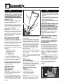
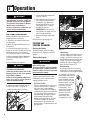
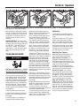
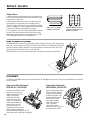
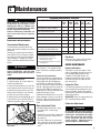
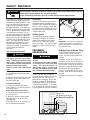
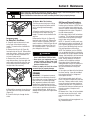
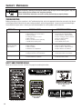
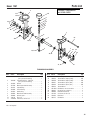
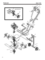
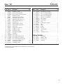
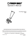
Operator’s Manual
Tiller/Edger Model
128T
IMPORTANT:READ SAFETY RULES AND INSTRUCTIONS CAREFULLY
Warning: This unit is equipped with an internal combustion engine and should not be used on or near any unimproved forest-covered, brush-covered or grass-covered land unless the engine’s exhaust system is equipped with a spark arrester meeting applicable local or state laws (if any). If a
spark arrester is used, it should be maintained in effective working order by the operator. In the State of California the above is required by law (Section 4442 of the California Public Resources Code). Other states may have similar laws. Federal laws apply on federal lands. A spark arrester for the
muffler is available by contacting the service department at Troy-Bilt LLC, P.O. Box 361131 Cleveland, Ohio 44136-0019.
TROY-BILT LLC, P.O. BOX 361131, CLEVELAND, OH 44136-0019
PRINTED IN USA
FROM NO. 769-00155
(03/2002)
TABLE OF CONTENTS
Content
Page
Calling Customer Support . . . . . . . . . . . . . . . . . . . . . . . . . . . . . . . . . . . . . . . . . . . . . . . . . . . . 2
Safety . . . . . . . . . . . . . . . . . . . . . . . . . . . . . . . . . . . . . . . . . . . . . . . . . . . . . . . . . . . . . . . . . . . 3
Assembly. . . . . . . . . . . . . . . . . . . . . . . . . . . . . . . . . . . . . . . . . . . . . . . . . . . . . . . . . . . . . . . . . 5
Features and Controls. . . . . . . . . . . . . . . . . . . . . . . . . . . . . . . . . . . . . . . . . . . . . . . . . . . . . . . 7
Operation . . . . . . . . . . . . . . . . . . . . . . . . . . . . . . . . . . . . . . . . . . . . . . . . . . . . . . . . . . . . . . . . 8
Maintenance . . . . . . . . . . . . . . . . . . . . . . . . . . . . . . . . . . . . . . . . . . . . . . . . . . . . . . . . . . . . . . 11
Storage . . . . . . . . . . . . . . . . . . . . . . . . . . . . . . . . . . . . . . . . . . . . . . . . . . . . . . . . . . . . . . . . . . 13
Troubleshooting. . . . . . . . . . . . . . . . . . . . . . . . . . . . . . . . . . . . . . . . . . . . . . . . . . . . . . . . . . . . 14
Parts List . . . . . . . . . . . . . . . . . . . . . . . . . . . . . . . . . . . . . . . . . . . . . . . . . . . . . . . . . . . . . . . . . 15
Warrany Information . . . . . . . . . . . . . . . . . . . . . . . . . . . . . . . . . . . . . . . . . . . . . . . . . . . . . . . . Back Cover
FINDING MODEL NUMBER
This Operator’s Manual is an important part of your new Tiller/Edger. It will help you assemble, prepare and maintain
the unit for best performance. Please read and understand what it says.
Before you start assembling your new equipment, please locate the model plate on the equipment and copy the information from it in the space provided below. This information is very important if you need help from our Customer
Support Department or an authorized dealer.
•
You can locate the model number by looking at the rear surface of the tine shield. A sample model plate is explained below. For future reference, please copy the model number and the serial number of the equipment in
the space below
Copy Model Number Here
www.troybilt.com
TROY-BILT LLC
P. O. BOX 3 6 1 1 3 1
CLEVELAND, OH 44136
330-558-7220
866-840-6483
Copy Serial Number Here
ENGINE INFORMATION
The engine manufacturer is responsible for all engine-related issues with regards to performance, power-rating, specifications, warranty and service. Please refer to the engine manufacturer’s Owner’s/Operator’s Manual packed separately with your unit for more information.
CALLING CUSTOMER SUPPORT
If you have difficulty assembling this product or have any questions regarding the controls, operation or maintenance
of this unit, please call the Customer Support Department.
Call 1- (330) 558-7220 or 1- (866) 840-6483 to reach a Customer Support representative. Please have
your unit’s model number and serial number ready when you call. See previous section to locate this information. You will be asked to enter the serial number in order to process your call ..
For more details about your unit, visit our website at www.troybilt.com
2
Section
1
Safety
SPARK ARRESTER WARNING TO RESIDENTS OF CALIFORNIA AND SEVERAL OTHER STATES
Under California law, and under the laws of several other states, you are not permitted to operate an internal combustion engine
using hydrocarbon fuels on any forest, brush, hay, grain, or grass covered land; or land covered by any flammable agricultural crop
without an engine spark arrester in continuous effective working order.
The engine on the unit is an internal combustion engine which burns gasoline, a hydrocarbon fuel, and must be equipped with a
spark arrester muffler in continuous effective working order. The spark arrester must be attached to the engine exhaust system in
such a manner that flames or heat from the system will not ignite flammable material. Failure of the owner/operator of the unit to
comply with this regulation is a misdemeanor under California law (and other states) and may also be a violation of other state
and/or federal regulations, laws, ordinances or codes. Contact your local fire marshal or forest service for specific information
about which regulations apply in your area.
TRAINING
• Read this Owner’s Manual and the separate Engine Owner’s Manual very carefully before operating this equipment. Be
completely familiar with the controls and
the proper use of the equipment. Know
how to stop the unit and disengage the
controls quickly. A replacement Manual
is available by contacting your authorized
dealer or the Factory.
• Never allow children or untrained
adults to use this equipment. Let adults
operate the unit only if instructed
properly.
• Keep the area of operation clear of all
persons, particularly small children and
pets. Keep bystanders at least 25 feet
from the area of operation.
• Keep in mind that the operator or user
is responsible for accidents or hazards
occurring to other people, their property
and themselves.
• Familiarize yourself with all of the
safety and operating decals on this equipment and on any of its attachments or
accessories.
• Do not run engine in an enclosed area.
Engine exhaust contains carbon
monoxide gas, a deadly poison that is
odorless, colorless, and tasteless. Do not
operate this equipment near buildings,
windows, or air conditioning equipment.
• Do not allow hands or any other part of
the body or clothing near the rotating
tines or near any other moving part. The
tines begin to rotate forward once the
engine is started and the Throttle/Tines
Lever is squeezed. The tines continue to
rotate until the operator releases the
Throttle/Tines Lever.
• Before inspecting or servicing any part
of the equipment, shut off engine, make
sure all moving parts have come to a
complete stop, then disconnect spark
plug wire from spark plug and move wire
away from the plug.
• Do not operate this equipment if you are
under the influence of alcohol, medication,
or when you are tired or ill.
PREPARATION
• Thoroughly inspect the area where the
equipment is to be used and remove all
foreign objects.
• Make sure that the Throttle/Tines Lever
is released and is in the neutral position
before you begin to start the engine.
• Do not operate the machine without
wearing adequate outer garments. Avoid
loose garments or jewelry that could get
caught in moving parts of the machine or
its engine.
• Do not operate the equipment when
barefoot or when wearing sandals,
sneakers, or similar lightweight footwear.
Wear protective footwear that will protect
your feet and improve footing on all
surfaces.
• Wear approved safety glasses when operating this equipment. The operation of
any powered machine can result in foreign objects being thrown by high-speed
rotating parts.
• Do not till near underground electric
cables, telephone lines, pipes, or hoses.
If in doubt, contact your utility or telephone company to locate underground
services.
• Handle fuel with care. It is highly
flammable and has explosive vapors.
Take these precautions:
a. Use an approved fuel container.
b. Add fuel before starting the engine.
Never remove the cap of the fuel tank
or add fuel while the engine is running
or when the engine is hot. Operators
shall not smoke.
c. Keep matches, cigarettes, cigars,
pipes, open flames, and sparks away
from the fuel tank and fuel container.
d. Fill fuel tank outdoors and with extreme caution. Never fill fuel tank
when indoors. Use a funnel or spout
to prevent spillage.
e. Replace all fuel tank and fuel container
caps securely.
f. If fuel is spilled, do not attempt to start
the engine, but move the machine away
from the area of spillage and avoid creating any source of ignition until fuel
vapors have dissipated.
• Never make adjustments to your equipment when the engine is running or spark
plug wire is connected (unless specifically
recommended in Owner’s Manual).
OPERATION
Operator’s Position
RIGHT SIDE
LEFT SIDE
LEFT and RIGHT sides of the tiller are
from the operator’s position behind the
handlebars (unless noted otherwise).
• The correct operator’s position is when
you are standing behind and gripping
handlebar, facing forward toward the
engine. Do not leave this position while
using the Throttle/Tines Lever.
• Do not put hands or feet near or under
rotating parts.
3
Section 1: Safety
• Exercise extreme caution when on or
crossing gravel drives, walks or roads.
Stay alert for hidden hazards or traffic.
Do not carry passengers.
• After striking a foreign object, stop the
engine, let all moving parts come to a
complete stop, disconnect the spark plug
wire and prevent it from touching the
spark plug, then carefully inspect the machine for damage. Repair the damage
before restarting and operating the
machine.
• Exercise caution to avoid slipping or
falling.
• If the machine should start to vibrate
abnormally, stop the engine. Disconnect
the spark plug wire and prevent it from
touching the plug. Check immediately for
the cause. Vibration is generally a
warning of trouble. Fix the problem
before using the equipment again.
• Stop the engine, disconnect the spark
plug wire and prevent it from touching the
spark plug whenever you leave the equipment, before unclogging the tines, or
when making any repairs, adjustments or
inspections.
• Take all possible precautions when
leaving the machine unattended. Always
stop the engine. Disconnect the spark
plug wire and prevent it from touching the
plug.
• Before cleaning, repairing, or inspecting, stop the engine and make certain all moving parts have stopped. Disconnect the spark plug wire and prevent it
from touching the spark plug to avoid accidental starting.
• Never operate equipment without
proper guards, plates, or other protective
safety devices in place.
• Do not run the engine in an enclosed
area. The exhaust fumes from the engine
contain extremely dangerous carbon
monoxide gas. This gas is colorless,
odorless, tasteless and deadly poisonous.
• Keep children and pets away.
4
• Be aware that the equipment may unexpectedly bounce upward or jump forward
if the tines should strike extremely hard
packed soil, frozen ground, or buried obstacles such as large stones, roots or
stumps. If you are in doubt about the
tilling conditions, always use the following operating precautions to assist
you in maintaining control of the
equipment:
a. Stand behind the equipment, using
both hands on the handlebars. Relax
your arms, but use a secure hand
grip.
b. Start tilling at shallow depths, working
gradually deeper with each pass.
c. Clear the tilling area of all large stones,
roots, and other debris.
d. In an emergency, stop the tines by releasing the Throttle/Tines Lever on the
handlebar. To stop the engine, move
the engine On/Off switch to OFF.
• Do not overload the machine’s capacity
by attempting to till too deeply at too fast
a rate.
• Never operate the equipment on slippery surfaces. Look behind and use care
when backing up.
• Do not operate the equipment on a
slope that is too steep for safety. When
on slopes, slow down and make sure you
have good footing.
• Never allow bystanders near the unit.
• Only use attachments and accessories
that are factory-approved.
• Never operate the equipment without
good visibility or good light.
• Never operate the unit if you are tired,
or under the influence of alcohol, drugs,
or medication.
• Do not tamper with the engine governor settings on the machine; the governor controls the maximum safe operating speed and protects the engine and
all other moving parts from damage
caused by engine overspeed. Authorized
service shall be sought if a problem
exists.
• Do not touch engine parts which may
be hot from operation. Allow parts to
cool before inspecting, cleaning or
repairing.
• Remember: you can stop the tines by
releasing the Throttle/Tines Lever. Move
the engine On/Off switch to OFF to shut
the engine off.
• Never transport this machine when the
engine is running.
• Terminals and non-insulated electrical
parts shall be protected against shorting
during normal servicing, refueling or
lubrication.
• Use extreme caution when reversing or
pulling the machine toward you.
• Start the engine carefully according to
instructions and with feet well away from
the tines.
MAINTENANCE/STORAGE
• Keep the tiller, attachments and accessories in safe working condition.
• Check all nuts, bolts, and screws at frequent intervals for proper tightness to be
sure equipment is in safe working
condition.
• Never store equipment with fuel in fuel
tank inside a building where fumes may
reach an open flame or spark (hot water
and space heaters, furnaces, clothes
dryers, stoves, electric motors, etc.).
• Allow the engine to cool before storing
the equipment.
• Keep the engine free of grass, leaves,
or grease to reduce the chance of a fire
hazard.
• Store gasoline in a cool, well-ventilated
area, safely away from any spark- or
flame-producing equipment. Store gasoline in an approved container, safely away
from the reach of children.
• Never perform maintenance when
engine is running or spark plug wire is
connected unless instructed to do so.
• If fuel tank must be drained, do so
outdoors.
• Follow manufacturer’s recommendations for safe loading, unloading, transport and storage of machine.
Section
2
Assembly
DANGER
WARNING
To prevent personal injury or property
damage, do not start the engine until all
assembly steps are complete and you
have read and understand the safety and
operating instructions in this manual.
B
C
INTRODUCTION
Read these instructions in their entirety
before you attempt to assemble or operate your new equipment.
The Border/Edger Attachment (H, Figure
5) does not need to be installed until you
are ready to do edging projects (refer to
instructions in this Section).
IMPORTANT: The correct mixture of unleaded automotive gasoline and two-cycle
motor oil (a 24:1 ratio of gasoline to twocycle oil) must be added to the fuel tank
before starting the engine. See instructions in this Section.
UNPACKING INSTRUCTIONS
1. Inspect your machine immediately. If
you find or suspect damage to the carton
or contents, contact your local authorized
dealer or the Factory for assistance.
2. Remove any packing material. Check
for small parts before discarding the
packing material. Loose parts include the
following:
(1) Bottle of 2-Cycle Oil
(1) Wheel (for edging)
(1) Edger Tine
(2) *Long Bushings
(1) *Short Bushing
* Packed in a separate plastic bag.
3. Perform the assembly on a clean, level
surface. Be careful not to severely bend
any of the control cables on the unit.
4. Before starting any assembly steps,
disconnect the engine spark plug wire
from the spark plug.
ASSEMBLY STEPS
STEP 1: Unfold and
Adjust Handlebars
IMPORTANT: Be careful not to pinch any
wires or cables while unfolding and adjusting the handlebars.
1. Loosen the two handlebar knobs (A,
Figure 1) and unfold the handlebars into
the operating position. Do not use force
— if there is binding, continue to loosen
the knobs.
A
C
A
C
Figure 1: Loosen handlebar knobs and
unfold handlebars. Slide plastic ties to the
locations shown.
2. There are two height settings holes in
the upper handlebar. The unit is shipped
with the handlebar knobs in the lowest
height setting holes. If this height is correct for you, simply tighten the two handlebar knobs. If a higher setting is desired, reposition the handlebar knobs,
mounting screws and washers in the
other set of holes.
3. Check the locations of the three plastic
ties (C, Figure 1). The ties must be positioned as shown.
NOTE: There is just one handlebar storage
position – folded over the engine as originally shipped.
STEP 2: Inspect
and Tighten Hardware
Check all nuts, bolts and screws on your
unit and tighten as needed. NOTE: Use a
7/16" socket with an extension to check
hardware at ends of handlebar.
Tools Needed to Check for Loose
Hardware:
• Adjustable wrench
• Slotted-head screwdriver
• Phillips-head screwdriver
• 7/16" socket and extension
IMPORTANT: Do not tighten engine governor screw (D, Figure 2). It is factoryadjusted for proper engine operation.
• Gasoline and its vapors are highly
flammable and explosive. Keep gasoline away from possible ignition
sources.
• Do not smoke while mixing the gasoline and two-cycle oil together or
when filling the fuel tank.
• Never fill fuel tank when engine is running or hot.
Failure to follow these precautions could
result in the fuel igniting, causing personal injury or property damage.
STEP 3: Add a Mixture of Gasoline
and Two-Cycle Oil to the Fuel Tank
IMPORTANT: Read the separate Engine
Owner’s Manual before starting the
engine.
1. Use clean, high quality 2-cycle oil,
NMMA TC-WII or TC-W3. DO NOT USE
MULTI-VISCOSITY OIL!
2. Use fresh, clean, unleaded regular,
unleaded premium or reformulated automotive gasoline only. DO NOT USE
LEADED GASOLINE.
NOTE: Do not use gasoline containing
methanol (wood alcohol). Fuel containing
up to 10% ethanol (gasohol) or up to
15% MTBE (Methyl Tertiary Butyl Ether)
may be used, but requires special care
when the engine is not used for extended
periods. See “STORAGE” instructions in
Engine Owner’s Manual for additional information.
3. The fuel/oil mix ratio is 24:1 with the
use of a NMMA classified oil. For new
engines, use twice the normal oil quantity
for the first gallon of fuel. NOTE: Due to
differences in fuel and oil availability
worldwide, Tecumseh recommends a
16:1 mix ratio if NMMA oil is not
available.
D
Figure 2: Do not adjust or tighten the engine
governor screw.
5
Section 2: Assembly
Chart 1: FUEL MIXTURE
(Mixture Ratio is 24 parts gasoline to
1 part two-cycle oil)
U.S. Gas
U.S. Oil
1 Gal.
2 Gal.
Metric Petrol
5 oz.
11 oz.
Metric Oil
4 liters
8 liters
167 ml
333 ml
4. Do not mix fuel directly in engine fuel
tank. Always use a clean, safety-approved fuel container.
• To Mix:
A. Fill a clean, approved container one
quarter full with recommended
gasoline.
B. Add recommended amount of oil per
Chart 1: FUEL MIXTURE.
C. Screw cap on container and shake
vigorously. Then unscrew cap and
fill container with gasoline per
Chart 1: FUEL MIXTURE. Screw on
cap and shake again. Once mixed,
oil and gasoline will not separate.
Fill Fuel Tank:
1. Engine must be cool. Clean area
around fuel tank cap and remove cap.
Insert a clean funnel into the fuel tank.
2. Slowly pour gasoline/oil mixture into
fuel tank. Fill tank no higher than 1/2"
from top of tank to allow for gasoline expansion. Install fuel cap and clean up any
fuel spills.
STEP 4: To Make Borders and Edges,
Install the Edger Attachment
To create borders or edges near walks,
driveways, flower beds, etc., you must
remove the four tine sections and install
the Edger Attachment (this attachment
was supplied with the unit – see Page 5).
To Install the Edger Attachment:
1. Gather together the following parts
(see Figure 4): (A) Border/Edger Tine; (B)
Long Bushing; (C) Border/Edger Wheel
and (D) Short Bushing.
2. Prop the machine carefully on the front
of the tubular carrying handle. The work
surface should be firm and flat. NOTE:
Usually the Border/Edger Tine is mounted
on the right-side of the unit for righthanded persons, and on the left-side of
the unit for left-handed persons.
3. Remove the hitch pin on each tine
shaft (E, Figures 3 and 4).
4. It is important for proper tilling performance that the tine sections be later reinstalled in their original patterns. Mark the
position of each tine section (Left-Outer,
Left-Inner, etc.) before removing them.
Refer to Figures 3 and 9 for tine pattern
information. See also Tine Removal and
Installation in Section 5.
5. Install the short bushing (D, Figure 4)
on the right-hand or left-hand tine shaft.
Then place the Border/Edger wheel (C) on
E
Figure 3: Remove hitch pins and tines from
both sides of the tine shaft. Keep left and
right-side tines separated and marked for
easier reinstallation.
the same shaft – the wheel hub should
face toward the tiller. Insert the hitch pin
through the rounded side of the tine
shaft.
6. Slide the long bushing (B) on the opposite side shaft. Then install the
Border/Edger tine (A) and secure it with
the hitch pin.
See Section 4 for instructions on using
the Border/Edger Attachment.
See Tine Removal and Installation in Section 5 for information on how to reinstall
the tines.
C
WARNING
Contact with rotating tines or other
moving parts can cause serious personal injury.
Before installing or removing attachments, or adjusting or servicing the machine, stop the engine, let all moving
parts come to a complete stop, disconnect the spark plug wire and move the
wire away from the spark plug.
D
E
A
E
B
Figure 4: The Border/Edger tine (A) can be mounted on left or right
sides of machine (with long bushing B). The Border/Edger wheel
(C) mounts on the other side (with short bushing D).
6
Section
3
Features and Controls
KNOW YOUR EQUIPMENT
READ THIS OWNER’S MANUAL AND ALL SAFETY RULES BEFORE OPERATING YOUR EQUIPMENT. Know the
location and function of all features and controls on the equipment. Save this manual for future reference.
WARNING
Before operating your machine, carefully read and understand all safety, controls, and operating instructions in this
Manual, the separate Engine Owner’s Manual and on the
decals on the machine.
Failure to follow these instructions can result in serious
personal injury.
Handlebar Height Adjustment Knob (B, Figure 5)
Two height settings, plus a storage position are available.
Refer to Assembly Steps, STEP 1 in Section 2 for adjustment
instructions.
Tilling Depth Adjustment Knob (C, Figure 5)
Loosening the knob enables you to move the wheel bracket
(K) up or down on the height adjustment bar (L). This controls the tilling depth.
IMPORTANT: Do not move the wheel bracket any higher than
the top of the adjustment bar.
Adjustable Tine Patterns (D, Figure 5)
The four tine sections are assembled at the factory for maximum performance under a wide variety of conditions. If
needed, the tines can be arranged for narrower tilling or close
cultivating. The tines can also be arranged to till very stony
soil. See Adjusting Tine Patterns in Section 4 for details.
H
G
J
B
J
Carrying Handle (E, Figure 5)
When the handlebar is folded in the storage position the unit
can be carried by the carrying handle. The carrying handle
also serves as a tie-down anchor point.
Edger Attachment (H, Figure 5)
Use this separate attachment to create borders or edges
along walks, driveways, flower beds, etc. See Section 4 for
details on installing and using this attachment.
Engine Controls
E
Engine On/Off Switch (A, Figure 5)
Use the engine On/Off Switch to start or stop the engine. See
Starting and Stopping the Engine in Section 4 and the Engine
Owner’s Manual for details.
B
F
J
C
K
L
A
D
Figure 5: Features and controls.
M
ENGINE DETAIL
Throttle/Tines Lever (G, Figure 5)
Squeeze this lever to start tine rotation and to vary the tine
speed. Release the lever to stop all tine motion. See Starting
and Stopping the Engine in Section 4 for details.
IMPORTANT: Do not squeeze this lever when starting the
engine.
Engine Recoil Start Rope (F, Figure 5)
Use the recoil start rope to start the engine. See Starting and
Stopping the Engine in Section 4 and the Engine Owner’s
Manual for details.
Fuel Primer Bulb (M, Figure 5)
Use the fuel primer bulb to help start the engine under certain
conditions. See Starting and Stopping the Engine in Section
4 and the Engine Owner’s Manual for details.
7
Section
4
Operation
a. Loosen tilling depth adjustment
knob (A, Figure 6).
WARNING
Before operating the unit carefully read
and understand all safety, control and
operating instructions in this Manual,
the separate Engine Owner’s Manual
and the decals on the machine.
Failure to follow these instructions can
result in serious personal injury.
PRE-START PREPARATION
Before starting the engine, perform the
following checks and services:
1. Disconnect the spark plug wire from
the spark plug.
2. Move the engine On/Off switch to the
OFF position.
3. Check the three plastic cable ties (J,
Figure 5). Be sure that cables and ties are
positioned as shown. Do not kink or
pinch the control cables in the handlebar.
4. Adjust handlebar height to desired position (see Assembly Steps, STEP 1: in
Section 2).
5. Check hardware for tightness.
DANGER
GASOLINE IS HIGHLY FLAMMABLE AND
ITS VAPORS ARE EXPLOSIVE.
Follow the gasoline safety rules in this
Manual (Section 1) and in the separate
Engine Owner’s Manual.
Failure to follow gasoline safety instructions can result in serious personal
injury and property damage.
6. Add the correct fuel mixture (see Assembly Steps, STEP 3: in Section 2).
7. Adjust the tilling depth as follows:
A
B
C
Figure 6
8
b. Move wheel bracket (B, Figure 6)
up in relation to the height adjustment bar (C). Moving the
bracket upward results in shallower tilling, which is recommended for initial use.
High-Volume
Priming Position
IMPORTANT: Do not move the
wheel bracket any higher than the
top of the adjustment bar.
c. Retighten the depth adjustment
knob.
8. Reconnect the spark plug wire.
STOPPING AND
STARTING THE ENGINE
Stopping the Engine
To stop the engine, move the engine
On/Off Switch (A, Figure 5) to the OFF
position.
Starting the Engine
WARNING
Do not squeeze the Throttle/Tines Lever
while starting engine.
Tines may propel the machine forward if
the engine speed is advanced from idle.
Failure to comply can result in personal
injury or property damage.
1. Move engine On/Off Switch to ON.
2. Determine which of the next three
starting conditions to use:
First Time Starting:
Use this starting method to start a new
engine for the first time, or after running out of gas, or after extended
storage. Use thumb and forefinger to
squeeze the side of the primer bulb that
is in line with the light colored rib on
the primer body, as shown in Figure 7
(High-Volume Priming Position).
Squeeze the primer bulb six (6) times.
This process removes air from the
priming system. As fuel enters the
priming system, the priming action will
feel more firm.
Standard-Volume
Priming Position
Figure 7
Cold Starting:
Use this starting method after the unit
has been sitting or has been in brief
storage, and has fuel in the tank. Use
the Standard-Volume Priming Position
(Figure 7) and push in top of primer
bulb two (2) times for above 550F, or
three (3) times if below 550F.
Warm Starting:
Do not use the primer to restart the
engine after it has been stopped after
running and has not cooled completely.
3. Stand with your feet positioned safely away from the
tines (Figure 8). Hold the
upper handlebar with one
hand. Use the other hand
to pull the recoil start rope
out slowly until you feel
resistance. Let rope
rewind slowly. Then,
quickly pull the rope all
the way out. Do this
up to ten (10) times.
Let the start rope
rewind slowly and
completely each time.
Figure 8
Section 4: Operation
B
A
C
Figure 9: “A” - all four tine gangs in standard pattern; “B” - two outer gangs removed for narrow tilling; “C” - the two inner gangs have
been swapped for stony tilling conditions.
Allow the engine to warm up for several
seconds. If engine either fails to start or
to continue running, push in primer bulb
two (2) times. Grasp starter rope and
pull with a rapid, full stroke, up to ten
(10) times.
TROUBLESHOOTING: Push the primer
bulb in two (2) more times. Using a rapid
full stroke, pull out the starting rope up to
ten (10) times. If engine still does not
start, wait 15 minutes. Do not prime
engine further. Grasp start rope and pull
with a rapid, full stroke up to ten (10)
times.
TILLING AND CULTIVATING
WARNING
Keep away from rotating tines. Rotating
tines will cause serious personal injury.
Use your machine to break up sod, prepare seedbeds and for cultivating in gardens and flower beds. It is easy to operate, but it is important that you start out
slowly and read this Section thoroughly
before putting it to use. Let the machine
do most of the work. The tines will pull
the machine forward, letting you adjust
forward speed by pressing down or lifting
the handlebars.
1. Roll the machine to the work area.
2. Adjust the tilling depth to the desired
position (see Pre-Start Preparation, previous page).
Stand behind the handlebar and push
down on the bar to raise the tines off the
ground. Squeeze the Throttle/Tines
Lever– the engine should speed up and
the tines start rotating. Release the
Throttle/Tines Lever to return to idle, the
tines should stop rotating or they may
rotate very slowly. Lowering them back
to the ground should stop any rotation.
NOTE: If tines continue to rotate when
engine is idling, either the idle speed is
too high or the centrifugal clutch is malfunctioning. If this occurs, contact the
Factory or your local authorized dealer.
4. Squeeze the Throttle/Tines Lever to
start the tines rotating. Lower the tines to
begin tilling. Firmly hold the handlebar to
prevent the machine from moving forward too quickly and to allow enough
time for the tines to dig deeply enough.
Adjust engine speed to suit the tilling
conditions. Remember that the rotating
tines help to pull the machine forward.
Use slower speeds and a shallow depth
setting when learning to use the unit and
whenever you are tilling on hard, rough or
uneven ground.
5. Do not try to till too deeply in the first
pass through sod or very hard ground. If
the machine jumps or bucks, use a shallower depth setting and reduce the engine
speed. With each successive pass, till
more deeply.
6. Apply downward pressure on the handlebars for shallower tilling. Lift the handlebars to dig more deeply. If the machine stays and tills in one spot, try
swinging the handlebars from side to side
to start moving forward again.
7. For easier tilling, water very hard soil a
few days before tilling. Avoid working
soggy or wet soil. Wait a day or two after
heavy rain for the ground to dry.
Cultivating
1. Cultivating is shallow tilling that disrupts weeds and aerates the upper crust
of soil.
2. Do not till deeper than 1"-2" to avoid
injuring nearby plant roots. Cultivate
often, so that weeds do not grow large
and cause needless tangling in the tines.
3. With careful planning, you can space
the seed rows far enough apart to allow
sufficient room for the machine to cultivate after the plants have grown.
Adjusting Tine Patterns
Depending upon the tilling project, you
have a choice of three tine patterns:
Wide (Standard) Tine Pattern – As
shipped from the factory, the unit is set
up for general tilling and cultivating. This
10" wide tine pattern (the maximum tilling
width) uses all four tine sections
(A, Figure 9). See Tine Removal and Installation in Section 5 for detailed information on how to set up this tine pattern.
Narrow Tine Pattern – For a narrow,
4-1/2" tilling width, remove the outside
tine section on the left- and right-sides
(B, Figure 9). See Tine Removal and Installation in Section 5 for detailed information on how to set up this tine pattern.
Stony Soil Tine Pattern – When tilling
deeply in stony soil, stones may become
jammed between the inner tines and the
machine hood. This pattern swaps the
two inner tines to minimize jamming (C,
Figure 9). See Tine Removal and Installation in Section 5 for detailed information
on how to set up this tine pattern.
3. Start the engine (see Stopping and
Starting the Engine, previous page).
9
Section 4: Operation
Tilling Patterns
1. When preparing a seedbed, go over the same path twice in
the first row, then overlap one-half the machine width on each
successive pass (Figure 10).
2. After going up and down the rows in one direction, make
second passes at a right angle across the original passes
(Figure 11). Again, overlap each pass to thoroughly pulverize
the entire seedbed area. In very hard ground, it may take three
or four passes before the desired depth is achieved.
Figure 10: Use an overlap
technique on every pass.
3. If your garden is not wide enough to till lengthwise and then
crosswise, then first overlap by one-half the machine width,
followed by successive passes at one-quarter machine width.
This overlapping method assures thorough tilling.
Figure 11: Make a second set
of passes at a right angle over
the first set of passes.
USING THE EDGER ATTACHMENT
The Edger Attachment makes clean, sharp edges next to walkways, driveways, paths, planted areas,
patios, etc. See Assembly Steps, STEP 4: in Section 2 for instructions on attaching this attachment.
Take your time when edging. Decide how far away the edge is to be from the walk or drive, then
slowly proceed using the walk or drive as your sight line.
Other attachments are can be purchased separately. See Attachments below for more details.
ATTACHMENTS
The following Tiller/Edger attachments are available where the Tiller/Edger was purchased. See your authorized dealer or contact the
Factory for details.
10
Power Lawn Rake Attachment –
OEM-290-263 / 290-263-081
Lawn Aerator Attachment –
OEM-290-264 / 290-264-081
The Power Lawn Rake will help
keep your lawn healthy and
vigorous. Matted grass and
debris not only looks
unattractive, but stifles
lawn growth and overall
health. This attachment
mounts without tools and
features dozens of tempered steel “fingers” that
spring off the surface to penetrate and loosen matted grass
without disturbing root growth. An 18"wide swath covers a large lawn area quickly.
Helps promote healthy, dense
lawns by aerating and loosening the soil to contribute
to better root growth. Four
tempered steel tines puncture the surface of the
lawn, letting nutrients
more easily reach the
roots. Assembles
without tools. When
mounted, it takes the place of
the standard tine sections.
Section
Maintenance
5
REQUIRED MAINTENANCE SCHEDULE
WARNING
REQUIRED MAINTENANCE
Before inspecting, cleaning or servicing
the machine, shut off engine, let all
moving parts come to a complete stop,
disconnect the spark plug wire and move
the wire away from the spark plug.
Failure to follow these instructions can
result in personal injury or property
damage.
Before
Each
Use
Clean Engine Cooling System
Every Every
25
75
Hours Hours
•
Check Transmission Lubricant
• (1)
Service Air Filter
• (2)
Inspect Spark Plug
Transmission Maintenance
Clean Machine
The transmission was lubricated at the
factory and should not require any further
lubrication.
However, you should check the lubricant
level after the first five (5) hours of operation and every twenty-five (25) operating
hours thereafter. If needed, use a highquality, automotive-grade petroleum-base
grease.
Clean Engine Exhaust Ports
(see Factory or authorized Dealer)
Clean Tine Shaft
(1) – After first five (5) hours of use.
(2) – Clean daily when conditions are
extremely dusty or dirty.
(3) – Check spark plug annually or every 100
operating hours.
End
of
Season
•
Check Tightness of Bolts and Nuts
EQUIPMENT MAINTENANCE
•
• (3)
•
•
•
Hardware
Before each use, check that all hardware
is in place and tightened securely.
ENGINE MAINTENANCE
WARNING
Before tipping engine or equipment to
service transmission, drain fuel from
tank by running engine until fuel tank is
empty.
To check the transmission:
1. Stop the engine, let it cool and disconnect the spark plug wire.
2. Place the machine down on its left side
so the right end of the tine shaft faces up.
3. Remove the right-side tines (see Tine
Removal and Installation in this Section).
4. Clean the transmission housing.
5. Remove the three threaded plugs (A, B
and C, Figure 14) from the transmission.
Lubricant should be visible in the top two
D
After
Each
Use
holes (B and C). If so, replace all three
plugs. If lubricant is needed, proceed as
follows.
To lubricate the transmission:
1. Place the nozzle of a standard grease
gun (D, Figure 14) firmly against the rim
of the middle hole (B) and add grease
until it begins to seep from the bottom
hole (A). Reinstall the plug in the bottom
hole (A). Next apply grease to the top fill
hole (C) until it begins to seep from the
middle hole (B). Reinstall the plugs in the
middle (B) and top (C) holes.
2. Before reinstalling the tines, use a fine
grade sandpaper to clean any rust off the
tine shaft. Apply a few drops of oil to the
tine shaft to make future tine removal
easier.
Engine Lubrication
The engine is a two-cycle engine. Lubrication is provided by mixing two-cycle oil
with unleaded regular gasoline as described in the Assembly Section. Attempting to operate the engine on gasoline alone will cause the engine to overheat and seize up.
Engine Air Filter
It is extremely important that air filter service be performed according to the maintenance schedule. Refer to the separate
Engine Owner’s Manual for inspection and
cleaning instructions.
IMPORTANT: Never run engine without air
filter assembly properly installed.
Carburetor Adjustment
Other Lubrication Points
A
B
C
Figure 14: Transmission lubricant check and
fill locations.
• Handlebar Adjustment Knobs: Spray
occasionally with a silicone type
lubricant.
• Throttle/Tines Lever Cable: Squeeze the
lever closed and spray a lubricant into
the cable area.
• Tine Shaft: After each use, remove the
tines, clean the tine shaft with sandpaper
and apply a light coat of oil to the tine
shaft.
WARNING
Do not tamper with the engine governor
screw which is factory-set for the proper
engine speed. Overspeeding the engine
beyond the factory high speed setting
can be dangerous and will void the
engine warranty. Authorized service
shall be sought if a problem exists.
11
Section 5: Maintenance
WARNING
Before inspecting, cleaning or servicing the machine, shut off engine, wait for moving parts to stop, disconnect spark plug wire and move wire away from spark plug.
Failure to follow these instructions can result in serious personal injury or property damage.
If the engine is running poorly or has low
power while tilling, an adjustment to the
carburetor may solve the problem. However, first inspect and service the spark
plug and the air filter before making a
carburetor adjustment. If the engine continues to run poorly (and the fuel mixture
is fresh), proceed to the following carburetor adjustment instructions.This factory-engineered instruction is designed to
provide continued optimum engine operating performance after the engine breakin period, which is approximately 5 to 10
hours. The adjustment, when properly
performed as described below, will not
void the engine warranty. A common
screwdriver is needed. If you prefer, see
an authorized engine dealer for
adjustment.
Prior to Carburetor Adjustment:
WARNING
The temperature of the muffler and adjacent engine areas may exceed 150 oF
(65oC). Contact may cause burns. Avoid
these areas. Remove the spark plug
lead and ground the lead to the engine to
prevent accidental starts and fires.
Failure to do this could cause personal
injury.
1. Let engine cool for 30 minutes before
continuing.
2. From the operator’s position behind the
handlebars, lay the machine down on its
left side (muffler side).
Carburetor Adjustment:
1. Locate the carburetor idle mixture
screw (Figure 15). It is directly under the
air filter and is black.
Do Not Adjust Silver-Colored Screw.
2. Turn the black idle mixture screw 1/16
of a turn clockwise.
3. Return the unit to its normal upright
operating position and reconnect the
spark plug wire.
If the engine continues to run poorly, contact an authorized engine dealer.
Spark Plug
A
Inspect the spark plug annually or every
100 operating hours according to the instructions in the separate Engine Owner’s
Manual. Check that the gap is set at .030".
For replacement use Champion RCJ-6Y or
equivalent (a resistor spark plug must be
used for replacement).
Cooling System
It is important to frequently check and
remove grass clippings, dirt and other
debris that accumulates on the engine,
cooling fins, air intake screen and on
levers and linkages. This helps to ensure
adequate air cooling and correct engine
speed.
Figure 16: Remove hitch pin (A) to take off
tines.
IMPORTANT: The hitch pin (A, Figure 16)
is under spring tension – wear gloves to
protect your fingers when removing or replacing the hitch pin.
Arranging Tines for Narrow Tilling
TINE REMOVAL
AND INSTALLATION
WARNING
Avoid contact with the cutting edges on
the tines.
To avoid personal injury when removing
or installing tines, wear heavy work
gloves. The engine must be off, all
moving parts stopped, and the spark
plug wire disconnected from the spark
plug and moved away from the plug.
The tines will wear with use and they
should be replaced if tilling seems to take
longer than usual or if the soil is not
being mixed as thoroughly. Also, in addition to the standard 10" tilling width tine
configuration, the tines can be arranged
in two other configurations: (1) A narrow,
41/2" tilling width for smaller areas and (2)
A special pattern for stony soil conditions.
1. Prop the machine forward so it rests
on the front of the tubular carrying
handle. The work surface should be flat
and firm.
2. Remove the hitch pin (A, Figure 16).
3. Remove the outer tine section (do not
remove inner tine section) and mark it as
to which side it is from (left or right) and
whether it’s an outer or inner tine section.
4. Slide one of the long bushings (B,
Figure 17), provided with the unit, onto
the shaft. Insert the hitch pin through the
tine shaft.
5. Repeat this procedure on the opposite
side.
Primer Bulb
Primer Line
Idle Speed Screw (Silver)
Idle Mixture Screw (Black)
Fuel Line
Fuel Tank
12
Figure 15: Idle Mixture Screw can be adjusted.
Section 5: Maintenance
WARNING
Before inspecting, cleaning or servicing the machine, shut off engine, wait for moving parts to stop, disconnect spark plug wire and move wire away from spark plug.
Failure to follow these instructions can result in serious personal injury or property damage.
B
Figure 17: Narrow tilling tine positions.
Arranging Tines
for Stony Soil Conditions
1. Prop the machine forward so it rests
on the front of the tubular carrying
handle. The work surface should be flat
and firm.
2. Remove the hitch pin (A, Figure 16)
from both sides of the unit. Remove both
outer tine sections. Mark each section as
a left or right side tine and whether it is
an inner or outer section.
3. Remove the inner tine sections and
swap their positions (the inner right-side
section goes onto the left side of the machine, and the inner left-side goes onto
the right side of the machine).
To Replace Worn Tine Sections:
The tines are excessively worn if tilling
takes much longer than before and the
soil is not being mixed thoroughly
enough.
1. Prop the machine forward so it rests
on the front of the tubular carrying
handle. The work surface should be flat
and firm.
2. Remove the hitch pin (A, Figure 16)
from both sides of the unit. Remove the
old tine sections and replace them with
new tine sections. Refer to Figure 16 and
the tine pattern shown in the Parts List
for tine pattern details. Insert the hitch
pins through the tine shafts.
WARNING
• Never store your equipment when
there is fuel mixture in the fuel tank.
• Never place your equipment near any
source of sparks or open flame (such
as from a hot water heater, a space
heater or clothes dryer).
Failure to comply can result in serious
personal injury or property damage.
STORAGE
Figure 18: Stony soil tine pattern.
4. Reinstall the two outer tine sections on
the sides from which they were removed
(Figure 18).
5. Insert the hitch pins through the tine
shafts.
IMPORTANT: It is important to prevent
gum deposits from forming in essential
fuel system parts such as carburetor, fuel
filter, fuel hose, or tank during storage.
Also, experience indicates that alcoholblended fuels (called gasohol or using
ethanol or methanol) can attract moisture
which leads to separation and formation
of acids during storage. Acidic gas can
damage the fuel system of an engine while
in storage.
Off-Season Storage Procedure
1. Drain the fuel tank of all of the gasoline/two-cycle oil mixture. NOTE: Do not
use a fuel mixture that is older than one
season in order to avoid varnish deposits
throughout the fuel system. Dispose of
the fuel mixture properly.
2. Start engine and run until fuel mixture
is used up. This will prevent poor performance from stale fuel when your equipment is taken out of storage.
NOTE: If “Gasohol” has been used, complete above instructions and then put 1/2
pint of gasoline properly mixed with twocycle oil (see Fuel Mixing Chart) into fuel
tank and repeat above instructions.
NOTE: Fuel stabilizer (such as STA-BIL)
is an acceptable alternative in minimizing
the formation of fuel gum deposits during
storage. Add stabilizer to the fuel mixture
in the fuel tank or the fuel storage container. Always follow the mix ratio instructions on the stabilizer container.
Run engine at least 10 minutes after
adding stabilizer to allow the stabilizer to
reach the carburetor. Do not drain the
gas tank and carburetor if using fuel
stabilizer.
3. Let engine cool down after fuel mixture
has been used up. Clean dirt and debris
from engine cooling fins, linkage and
other engine surfaces.
4. Pull starter handle slowly until resistance is felt due to compression pressure,
then stop. Release starter tension slowly
to prevent engine from reversing due to
compression pressure. This position will
close both the intake and exhaust ports to
prevent corrosion of the piston and
cylinder bore.
5. Remove tines. Clean all soil and debris
from dust covers and tine shaft. Lubricate tine shaft with light oil. Replace
tines.
6. Cover engine and store equipment in a
dry, sheltered location.
13
Section 5: Maintenance
WARNING
Before inspecting, cleaning or servicing the machine, shut off engine, wait for moving parts to stop, disconnect spark plug wire and move wire away from spark plug.
Failure to follow these instructions can result in serious personal injury or property damage.
TROUBLESHOOTING
Before performing any of the corrections in this Troubleshooting Chart, refer to the appropriate information contained in this Manual
and the Engine Owner’s Manual for the correct safety precautions and servicing procedures. Contact your local authorized Engine
Service Dealer for engine service. Contact your local authorized dealer for service problems with the machine.
PROBLEM
POSSIBLE CAUSE
CORRECTIVE ACTION
Engine does not start.
1. Spark plug wire disconnected.
2. Out of gas/two-cycle oil fuel mixture.
3. Stale fuel mixture.
4. Priming procedure not correct.
5. Dirty air filter(s).
6. Worn, corroded or broken spark plug.
7. On/Off Switch in OFF position.
1. Reconnect wire to spark plug.
2. Check fuel tank. Add fuel mixture.
3. Drain old mixture. Add fresh mixture.
4. Refer to starting procedure in manual.
5. Clean or replace air filters.
6. Replace spark plug.
7. Move On/Off Switch to ON.
Engine runs poorly or
has low power under
tilling conditions.
1. Fouled spark plug.
2. Dirty air filter(s).
3. Stale fuel mixture.
4. Carburetor out of adjustment.
1. Remove, inspect, clean spark plug.
2. Clean or replace dirty air filters.
3. Drain old mixture. Add fresh mixture.
4. Adjust carburetor. See Manual.
Engine overheats.
1. Engine cooling fins clogged.
2. Improper amount of oil in fuel mixture.
1. Remove dirt and debris from fins.
2. Drain tank; fill with correct mixture.
Tines stop rotating.
1. Object wedged between tines and hood.
2. Internal transmission problem.
1. Remove wedged object.
2. Authorized service dealer.
SAFETY AND OPERATING DECALS
Decals are not shown at full size. See Parts List pages for reordering information.
On right-side handlebar
On rear, right-side tine
shield
On rear, left-side
tine shield
On top, left-side tine shield
14
On top of handlebar
Parts List
Model 128T
Complete Transmission
Part # 986-04000
2
21
13
19
7
5
A
22
18
6
18
A
23
B
A
24
B
9
3
B
10
1
4
A
13
A
8
20
14, 15
5
3
16, 17
24
22
23
14, 15
11, 12
22
TRANSMISSION ASSEMBLY
Ref # Part #
1
1915039
2
1915040
3
4
5
6
7
8
9
10
11
1983632
1918307
1983731
1983636
1983637
1904416
1909923
1185741
710-0206
Description
Transmission Case - left-side.
(Incl. pressed-in bushing) . . . . . . . . . . . .
Transmission Case - right-side.
(Incl. pressed-in bushing) . . . . . . . . . . . .
Oil Seal . . . . . . . . . . . . . . . . . . . . . . . . . . . . .
Worm Input Shaft Assembly . . . . . . . . . . . . .
Input Bearing . . . . . . . . . . . . . . . . . . . . . . . .
Thrust Bearing . . . . . . . . . . . . . . . . . . . . . . .
Ball Bearing . . . . . . . . . . . . . . . . . . . . . . . . . .
Worm Gear Shaft Assembly . . . . . . . . . . . . .
Oil Seal, Input . . . . . . . . . . . . . . . . . . . . . . . .
Plug, 1/8 . . . . . . . . . . . . . . . . . . . . . . . . . . . .
Hex Screw, 1/4-20 x 7/8 . . . . . . . . . . . . . . . .
Qty.
1
1
2
1
2
1
1
1
1
3
5
Ref # Part #
13
14
15
16
17
18
19
20
21
22
23
24
712-0324
1983635
1983640
1983641
1983642
1983638
736-0463
1983663
1909486
1747166
1915055
1983713
Description
Qty.
Locknut, Nyloc, 1/4"-20 . . . . . . . . . . . . . . . . . 8
Thrust Washer, output (.050") . . . . . . . . . . . .A/R
Thrust Washer, output (.040") . . . . . . . . . . . .A/R
Thrust Washer, input (.020") . . . . . . . . . . . . .A/R
Thrust Washer, input (.035") . . . . . . . . . . . . .A/R
Thrust Washer . . . . . . . . . . . . . . . . . . . . . . . . 2
Flat Washer, .25 x .630 x .0515 . . . . . . . . . . . 2
Hex Hd. Screw, 1/4-20 x 5 . . . . . . . . . . . . . . 2
Clutch Drum and Hub . . . . . . . . . . . . . . . . . . 1
Set Screw, 1/4-28 x 3/8 . . . . . . . . . . . . . . . . . 4
Dust Cover . . . . . . . . . . . . . . . . . . . . . . . . . . 2
Felt Washer . . . . . . . . . . . . . . . . . . . . . . . . . . 2
A/R – As Required
15
Parts List
Model 128T
7
9
4
5
42
SEE PREVIOUS PAGE
6
49
3
42
13
1
48
46
47
13
8
45
16
44
45
15
44
18
14
13
17
21
18
19
37
35
42
36
31
32
19
42
38
24
27
34
43
23
39
33
25
41
40
26
28
22
29
30
16
40
Parts List
Model 128T
Ref # Part #
1
3
4
5
6
7
8
9
13
14
15
16
17
18
19
21
22
23
24
25
26
27
28
29
1918303
777I00007
777I00009
1917451
1918123
1750608
1731025
1909775
1763682
1918120
1918121
1909720
1983663
1107381
712-0324
1909487
1918124
777D06104
777S00012
777S30647
777S00013
1186292
1186387
736-0329
Description
Handlebar Assembly . . . . . . . . . . . . . . . . . .
Decal - Starting Stabilization . . . . . . . . . . . .
Decal - Throttle/Tines Lever Operation . . . . .
Handlebar Grip, PVC . . . . . . . . . . . . . . . . . .
Throttle/Tines Lever and Cable . . . . . . . . . . .
Pan Hd. Screw, #10-16 x 1-1/2 . . . . . . . . . .
Saddle Hd. Screw, 5/16-18 x 2 . . . . . . . . . . .
Spacer, Throttle/Tines Lever . . . . . . . . . . . . .
Plastic Wire Tie . . . . . . . . . . . . . . . . . . . . . .
Lower Handlebar - Left-Side . . . . . . . . . . . .
Lower Handlebar - Right-Side . . . . . . . . . . .
Foam Sleeve . . . . . . . . . . . . . . . . . . . . . . . . .
Hex Hd. Screw, 1/4-20 x 5 . . . . . . . . . . . . . .
Flat Washer, 1/4-20 . . . . . . . . . . . . . . . . . . .
Hex Locknut, 1/4-20 . . . . . . . . . . . . . . . . . . .
Clutch Rotor and Washer . . . . . . . . . . . . . . .
Tine Shield . . . . . . . . . . . . . . . . . . . . . . . . . .
Decal - Logo . . . . . . . . . . . . . . . . . . . . . . . . .
Decal - Warning, Rotating TInes . . . . . . . . .
Decal - Warning, Hot Surfaces . . . . . . . . . . .
Decal - Caution, Operation Hazards . . . . . . .
Hex Hd. Screw, #10-24 x 1/2 . . . . . . . . . . . .
Flange Locknut, #10-24 . . . . . . . . . . . . . . . .
Lock Washer, 1/4-20 . . . . . . . . . . . . . . . . . .
Qty.
1
1
1
2
1
1
2
1
3
1
1
1
2
2
5
1
1
1
1
1
1
2
2
4
Ref # Part #
30
31
32
33
34
35
36
37
38
39
40
41
42
43
44
45
710-0501
1909540
1909539
1909712
1909711
1909680
GW-90077
1909835
710-0206
1909517
1917754
GW-9532
1185590
1981022
1763767
1177038
Description
Hex Cap Screw, 1/4-20 x 2 . . . . . . . . . . . . . .
Outer Tine - Right-Hand Side . . . . . . . . . . . .
Inner Tine - Right-Hand Side . . . . . . . . . . . .
Outer Tine - Left-Hand Side . . . . . . . . . . . . .
Inner Tine - Left-Hand Side . . . . . . . . . . . . .
Wheel Bracket . . . . . . . . . . . . . . . . . . . . . . .
Carriage Bolt . . . . . . . . . . . . . . . . . . . . . . . .
Knob . . . . . . . . . . . . . . . . . . . . . . . . . . . . . .
Hex Hd. Screw, 1/4-20 x 1 . . . . . . . . . . . . . .
Axle . . . . . . . . . . . . . . . . . . . . . . . . . . . . . . .
Wheel . . . . . . . . . . . . . . . . . . . . . . . . . . . . . .
E-Ring . . . . . . . . . . . . . . . . . . . . . . . . . . . . .
Hitch Pin . . . . . . . . . . . . . . . . . . . . . . . . . . .
Tine Hood Cover . . . . . . . . . . . . . . . . . . . . .
Knob . . . . . . . . . . . . . . . . . . . . . . . . . . . . . .
Lock Washer, 5/16 . . . . . . . . . . . . . . . . . . . .
Qty.
4
1
1
1
1
1
1
1
3
1
2
4
2
1
2
2
EDGER ATTACHMENT
46
47
48
49
1903777
1903778
1983648
1915054
Edger Wheel . . . . . . . . . . . . . . . . . . . . . . . . .
Bushing - Short . . . . . . . . . . . . . . . . . . . . . .
Bushing - Long . . . . . . . . . . . . . . . . . . . . . .
Edger Tine . . . . . . . . . . . . . . . . . . . . . . . . . .
1
1
2
1
* Order parts from your local authorized engine dealer. Refer to engine nameplate
for model/type number.
17
Notes
18
Index
Accessories and Attachments . . . . . . . . . . . . . . . . . . . . . . .14
Aerator Attachment . . . . . . . . . . . . . . . . . . . . . . . . . . . . . . .14
Air Filter . . . . . . . . . . . . . . . . . . . . . . . . . . . . . . . . . . . . . . .11
Assembly . . . . . . . . . . . . . . . . . . . . . . . . . . . . . . . . . . . . . . .5
Borders . . . . . . . . . . . . . . . . . . . . . . . . . . . . . . . . . . . . . . . . .5
Border/Edger Attachment . . . . . . . . . . . . . . . . . . . . . .5, 6, 10
Carburetor . . . . . . . . . . . . . . . . . . . . . . . . . . . . . . . . . . . .7, 12
Control Lever, Throttle/Tines . . . . . . . . . . . . . . . .3, 4, 6, 9, 11
Cultivating . . . . . . . . . . . . . . . . . . . . . . . . . . . . . . . . . . . .9, 10
Decals . . . . . . . . . . . . . . . . . . . . . . . . . . . . . . . . . . . . . . . . . .2
Edging . . . . . . . . . . . . . . . . . . . . . . . . . . . . . . . . . . . . . . .5, 14
Engine
Air Filter . . . . . . . . . . . . . . . . . . . . . . . . . . . . . . . . . . . . .11
Carburetor . . . . . . . . . . . . . . . . . . . . . . . . . . . . . . . . .7, 12
Cleaning . . . . . . . . . . . . . . . . . . . . . . . . . . . . . . . . . .11, 13
Fuel Mixture . . . . . . . . . . . . . . . . . . . . . . . . . . .5, 6, 12, 13
Fuel Primer Bulb . . . . . . . . . . . . . . . . . . . . . .4, 8, 9, 12, 14
On/Off Switch . . . . . . . . . . . . . . . . . . . . . . . . . .4, 8, 14, 16
Operation . . . . . . . . . . . . . . . . . . . . . . . . . . . . . . . . . . . . .8
Recoil Start Rope . . . . . . . . . . . . . . . . . . . . . . . . . . . . . . .8
Spark Plug . . . . . . . . . . . . . . . . . . . . . . . . . . . . .11, 12, 14
Speed . . . . . . . . . . . . . . . . . . . . . . . . . . . . . . . . . . .7, 9, 12
Starting Engine . . . . . . . . . . . . . . . . . . . . . . . . . . . . . . . . .8
Stopping Engine . . . . . . . . . . . . . . . . . . . . . . . . . . . . . . . .8
Storage . . . . . . . . . . . . . . . . . . . . . . . . . . . . . . . .4, 5, 8, 13
Throttle/Tines Lever . . . . . . . . . . . . . . . . . . . .3, 4, 5, 9, 11
Features/Controls . . . . . . . . . . . . . . . . . . . . . . . . . . . . . . . . .7
Fuel Mixture . . . . . . . . . . . . . . . . . . . . . . . . . . . . .5, 6, 12, 13
Fuel Primer Bulb . . . . . . . . . . . . . . . . . . . . . . . .4, 8, 9, 12, 14
Gasoline/ Two-Cycle Oil . . . . . . . . . . . . . . . . . . . . .5, 6, 12, 13
Handlebar Height Adjustment . . . . . . . . . . . . . . . . . . . . . .7, 8
Hardware . . . . . . . . . . . . . . . . . . . . . . . . . . . . . . . . . . . . . . . .5
Lubrication . . . . . . . . . . . . . . . . . . . . . . . . . . . . . . . . . . . . .11
Maintenance . . . . . . . . . . . . . . . . . . . . . . . . . . . . . . . . . . . .11
Model/Serial Number . . . . . . . . . . . . . . . . . . . . . . .Back Cover
Oil/Gasoline Mixture . . . . . . . . . . . . . . . . . . . . . . .5, 6, 12, 13
Off-Season Storage . . . . . . . . . . . . . . . . . . . . . . . . . . . . . . .11
Operation . . . . . . . . . . . . . . . . . . . . . . . . . . . . . . . . . . . . . . .8
Parts List . . . . . . . . . . . . . . . . . . . . . . . . . . . . . . . . . . . .15-17
Power Lawn Rake . . . . . . . . . . . . . . . . . . . . . . . . . . . . . . . .10
Preparation . . . . . . . . . . . . . . . . . . . . . . . . . . . . . . . . . . . .3, 8
Recoil Starter Rope . . . . . . . . . . . . . . . . . . . . . . . . . . . . . . .98
Repair Parts . . . . . . . . . . . . . . . . . . . . . . . . . . . . . . . . . .15-17
Safety Rules . . . . . . . . . . . . . . . . . . . . . . . . . . . . . . . . . . . .3-4
Safety Decals . . . . . . . . . . . . . . . . . . . . . . . . . . . . . . . . . . . .2
Service Recommendation Checklist . . . . . . . . . . . . . . . . . .11
Spark Plug . . . . . . . . . . . . . . . . . . . . . . . . . . . . . . .11, 12, 14
Starter Rope . . . . . . . . . . . . . . . . . . . . . . . . . . . . . . . . . . . . .8
Storage . . . . . . . . . . . . . . . . . . . . . . . . . . . . . . . . . .4, 5, 8, 13
Tilling . . . . . . . . . . . . . . . . . . . . . . . . . . . . . . . . . . . . . . .9, 10
Tilling Depth Adjustment . . . . . . . . . . . . . . . . . . . . . . . . . . . .9
Tilling Widths . . . . . . . . . . . . . . . . . . . . . . . . . . . . . . . . . . . .9
Tine Removal . . . . . . . . . . . . . . . . . . . . . . . . . . . . . . . . . . .12
Tips/Techniques . . . . . . . . . . . . . . . . . . . . . . . . . . . . . . .9, 10
Troubleshooting . . . . . . . . . . . . . . . . . . . . . . . . . . . . . . .9, 14
Unpacking . . . . . . . . . . . . . . . . . . . . . . . . . . . . . . . . . . . . . . .5
W, X, Y, Z
19
MANUFACTURER’S LIMITED WARRANTY FOR:
The limited warranty set forth below is given by Troy-Bilt LLC with
respect to new merchandise purchased and used in the United
States, its possessions and territories.
d.
Troy-Bilt LLC warrants this product against defects for a period of
two (2) years commencing on the date of original purchase and
will, at its option, repair or replace, free of charge, any part found
to be defective in materials or workmanship. This limited warranty shall only apply if this product has been operated and maintained in accordance with the Operator’s Manual furnished with
the product, and has not been subject to misuse, abuse, commercial use, neglect, accident, improper maintenance, alteration,
vandalism, theft, fire, water, or damage because of other peril or
natural disaster. Damage resulting from the installation or use of
any accessory or attachment not approved by Troy-Bilt LLC for
use with the product(s) covered by this manual will void your warranty as to any resulting damage.
e.
Normal wear parts or components thereof are subject to separate terms as follows: All normal wear parts or component failures will be covered on the product for a period of 90 days regardless of cause. After 90 days, but within the two year period,
normal wear part failures will be covered ONLY IF caused by defects in materials or workmanship of OTHER component parts.
Normal wear parts and components include, but are not limited
to: batteries, belts, blades, blade adapters, grass bags, rider
deck wheels, seats, snow thrower skid shoes, shave plates,
auger spiral rubber, tires.
HOW TO OBTAIN SERVICE: Warranty service is available,
WITH PROOF OF PURCHASE, through your local authorized
service dealer. To locate the dealer in your area, check your
Yellow Pages, or contact Troy-Bilt LLC at P.O. Box 361131,
Cleveland, Ohio 44136-0019, 1-866-840-6483, or log on to our
Web site at www.troybilt.com.
This limited warranty does not provide coverage in the following
cases:
a. The engine or component parts thereof. These items
carry a separate manufacturer’s warranty. Refer to the
applicable manufacturer’s warranty for terms and cond
tions.
b. Log splitter pumps, valves, and cylinders have a separate
one year warranty.
c. Routine maintenance items such as lubricants, filters,
blade sharpening, tune-ups, brake adjustments, clutch
adjustments, deck adjustments, and normal deterioration of
the exterior finish due to use or exposure.
f.
g.
Troy-Bilt LLC does not extend any warranty for products
sold or exported outside of the United States, its possessions and territories, except those sold through TroyBilt LLC’s authorized channels of export distribution.
Parts that are not genuine Troy-Bilt parts are not covered by
this warranty.
Service completed by someone other than an authorized
service dealer is not covered by this warranty.
Transportation charges and service calls are not covered.
No implied warranty, including any implied warranty of merchantability of fitness for a particular purpose, applies after
the applicable period of express written warranty above as
to the parts as identified. No other express warranty,
whether written or oral, except as mentioned above, given
by any person or entity, including a dealer or retailer, with respect to any product, shall bind Troy-Bilt LLC. During the
period of the warranty, the exclusive remedy is repair or replacement of the product as set forth above.
The provisions as set forth in this warranty provide the sole
and exclusive remedy arising from the sale. Troy-Bilt LLC
shall not be liable for incidental or consequential loss or
damage including, without limitation, expenses incurred for
substitute or replacement lawn care services or for rental
expenses to temporarily replace a warranted product.
Some states do not allow the exclusion or limitation of incidental
or consequential damages, or limitations on how long an implied
warranty lasts, so the above exclusions or limitations may not
apply to you.
In no event shall recovery of any kind be greater than the amount
of the purchase price of the product sold. Alteration of the
safety features of the product shall void this warranty. You
assume the risk and liability for loss, damage, or injury to you and
your property and/or to others and their property arising out of
the misuse or inability to use the product.
This limited warranty shall not extend to anyone other than the
original purchaser or to the person for whom it was purchased as
a gift.
HOW STATE LAW RELATES TO THIS WARRANTY: This limited warranty gives you specific legal rights, and you may
also have other rights which vary from state to state.
TROY-BILT LLC, P.O. BOX 361131, CLEVELAND, OHIO 44136-0019, 1-866-840-6483