1
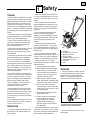
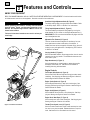
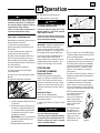
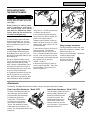
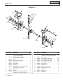
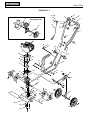
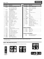
OWNER’S MANUAL
Tiller/Edger
SAFETY FIRST!
Before operating this equipment, read this
Owner's Manual and the separate manual
supplied by the engine manufacturer.
•
•
•
•
•
•
Safety
Assembly
Features and Controls
Operation
Maintenance
Parts List
Model
12228
GARDEN WAY INCORPORATED
2
Dear Owner:
Congratulations on your purchase of a Tiller/Edger with
Edger Attachment. It has been designed, engineered and
manufactured to give you the best possible dependability
and performance.
Please carefully read this Manual. It tells you how to safely
and easily assemble, operate and maintain your machine.
Be sure that you and any other operators carefully follow
the recommended safety practices at all times. Failure to
do so could result in personal injury or property damage.
Of course, if you should ever have any problems or questions, please contact your local authorized service dealer
(see back cover).
We want to be sure that you are completely satisfied at all
times.
See Back Cover for
Customer Service information
Safety Alert Symbol
This is a safety alert symbol. It is used in this
manual and on the unit to alert you to potential
hazards. When you see this symbol, read and
obey the message that follows it. Failure to obey
safety messages could result in personal injury or
property damage.
This machine meets voluntary safety standard
B71.8 – 1996, which is sponsored by the Outdoor
Power Equipment Institute, Inc., and is published
by the American National Standards Institute.
Table of Contents
SECTION 1: SAFETY ...........................................
Training.........................................................................
Preparation ...................................................................
Operation ......................................................................
Maintenance/Storage ....................................................
3
3
3
4
4
SECTION 2: ASSEMBLY........................................
Unpacking Instructions...............................................
Assembly Steps ..........................................................
5
5
5
SECTION 3: FEATURES AND CONTROLS .....................
6
SECTION 4: OPERATION ......................................
Pre-start Preparation ..................................................
Stopping and Starting the Engine ...............................
Tilling and Cultivating .................................................
Installing and Using the Edger Attachment.................
Attachments ...............................................................
7
7
7
8
9
9
SECTION 5: MAINTENANCE ..................................
Required Maintenance Schedule ................................
Equipment Maintenance .............................................
Engine Maintenance ...................................................
Tine Removal and Installation.....................................
Storage .......................................................................
Troubleshooting .........................................................
10
10
10
11
11
12
12
PARTS LIST ..................................................... 13
Safety and Operating Decals....................................... 15
CUSTOMER SERVICE INFORMATION.............. BACK COVER
WARNING
TO AVOID INJURY:
• READ THE OPERATOR’S MANUAL.
• KNOW LOCATION AND FUNCTION OF ALL CONTROLS.
• KEEP ALL SAFETY DEVICES AND SHIELDS IN PLACE AND
WORKING.
• NEVER ALLOW CHILDREN OR UNINSTRUCTED ADULTS TO
OPERATE MACHINE.
• SHUT OFF ENGINE AND DISCONNECT SPARK PLUG WIRE
BEFORE MANUALLY UNCLOGGING TINES OR MAKING
REPAIRS.
• KEEP BYSTANDERS AWAY FROM MACHINE.
• KEEP AWAY FROM ROTATING PARTS.
• USE EXTREME CAUTION WHEN REVERSING OR PULLING
THE MACHINE TOWARDS YOU.
3
Section
1 Safety
TRAINING
• Read this Owner’s Manual and the separate Engine Owner’s Manual very carefully
before operating this equipment. Be completely familiar with the controls and the
proper use of the equipment. Know how
to stop the unit and disengage the controls
quickly. A replacement Manual is available
by contacting your authorized dealer or the
Factory.
• Never allow children or untrained adults
to use this equipment. Let adults operate
the unit only if instructed properly.
• Keep the area of operation clear of all
persons, particularly small children and
pets. Keep bystanders at least 25 feet
from the area of operation.
• Keep in mind that the operator or user is
responsible for accidents or hazards
occurring to other people, their property
and themselves.
• Familiarize yourself with all of the safety
and operating decals on this equipment
and on any attachments or accessories.
• Do not run engine in an enclosed area.
Engine exhaust contains carbon monoxide
gas, a deadly poison that is odorless, colorless, and tasteless. Do not operate this
equipment near buildings, windows, or air
conditioning equipment.
• Do not allow hands or any other part of
the body or clothing near the rotating tines
or near any other moving part. The tines
begin to rotate forward once the engine is
started and the Throttle/Tines Control
Lever is squeezed. The tines continue to
rotate until the operator releases the
Throttle/Tines Control Lever.
• Before inspecting or servicing any part
of the equipment, shut off engine, make
sure all moving parts have come to a complete stop, then disconnect spark plug
wire from spark plug and move wire away
from the plug.
• Do not operate this equipment if you are
under the influence of alcohol, medication,
or when you are tired or ill.
PREPARATION
• Thoroughly inspect the area where the
equipment is to be used and remove all
foreign objects.
• Make sure that the Throttle/Tines Control Lever is disengaged and is in the neutral position before you begin to start the
engine.
• Do not operate the machine without
wearing adequate outer garments. Avoid
loose garments or jewelry that could get
caught in moving parts of the machine or
its engine.
• Do not operate the equipment when
barefoot or when wearing sandals,
sneakers, or similar lightweight footwear.
Wear protective footwear that will protect
your feet and improve footing on all
surfaces.
• Wear approved safety glasses when
operating this equipment. The operation
of any powered machine can result in foreign objects being thrown by high-speed
rotating parts.
• Do not till near underground electric
cables, telephone lines, pipes, or hoses. If
in doubt, contact your utility or telephone
company to locate underground services.
• Handle fuel with care. It is highly
flammable and has explosive vapors. Take
these precautions:
a. Use an approved fuel container.
b. Add fuel before starting the engine.
Never remove the cap of the fuel
tank or add fuel while the engine is
running or when the engine is hot.
Operators shall not smoke.
c. Keep matches, cigarettes, cigars,
pipes, open flames, and sparks away
from the fuel tank and fuel container.
d. Fill fuel tank outdoors and with
extreme caution. Never fill fuel tank
when indoors. Use a funnel or spout
to prevent spillage.
e. Replace all fuel tank and fuel container caps securely.
f. If fuel is spilled, do not attempt to
start the engine, but move the
machine away from the area of
spillage and avoid creating any
source of ignition until fuel vapors
have dissipated.
• Never make adjustments to your equipment when the engine is running or spark
plug wire is connected (unless specifically
recommended in Owner’s Manual).
A
C
B
D
E
F
G
H
A - Handlebar
B - Throttle/Tines Control Lever
C - Engine On/Off Switch
D - Carrying Handle
E - Handlebar Height Adjust Knob
F - Tilling Depth Adjust Knob
G - Tine Cover
H - Tines
OPERATION
• The correct operator’s position is when
you are standing behind and gripping the
handlebar, facing forward toward the
engine. Do not leave this position while
using the engine Throttle/Tines lever.
RIGHT SIDE
LEFT SIDE
LEFT and RIGHT sides of the tiller are
from the operator’s position behind the
handlebars (unless noted otherwise).
• Do not put hands or feet near or under
rotating parts.
4
Section 1: Safety
• Exercise extreme caution when on or
crossing gravel drives, walks or roads.
Stay alert for hidden hazards or traffic. Do
not carry passengers.
• After striking a foreign object, stop the
engine, let all moving parts come to a
complete stop, disconnect the spark plug
wire and prevent it from touching the
spark plug, then carefully inspect the
machine for damage. Repair the damage
before restarting and operating the
machine.
• Exercise caution to avoid slipping or
falling.
• If the machine should start to vibrate
abnormally, stop the engine. Disconnect
the spark plug wire and prevent it from
touching the plug. Check immediately for
the cause. Vibration is generally a
warning of trouble. Fix the problem before
using the equipment again.
• Stop the engine, disconnect the spark
plug wire and prevent it from touching the
spark plug whenever you leave the equipment, before unclogging the tines, or
when making any repairs, adjustments or
inspections.
• Take all possible precautions when
leaving the machine unattended. Always
stop the engine. Disconnect the spark
plug wire and prevent it from touching the
plug.
• Before cleaning, repairing, or
inspecting, stop the engine and make
certain all moving parts have stopped.
Disconnect the spark plug wire and
prevent it from touching the spark plug to
avoid accidental starting.
• Never operate equipment without
proper guards, plates, or other protective
safety devices in place.
• Do not run the engine in an enclosed
area. The exhaust fumes from the engine
contain extremely dangerous carbon
monoxide gas. This gas is colorless,
odorless, tasteless and deadly poisonous.
• Keep children and pets away.
• Be aware that the equipment may unexpectedly bounce upward or jump forward
if the tines should strike extremely hard
packed soil, frozen ground, or buried
obstacles such as large stones, roots or
stumps. If you are in doubt about the
tilling conditions, always use the following
operating precautions to assist you in
maintaining control of the equipment:
a. Stand behind the equipment, using
both hands on the handlebars. Relax
your arms, but use a secure hand
grip.
b. Start tilling at shallow depths,
working gradually deeper with each
pass.
c. Clear the tilling area of all large
stones, roots and other debris.
d. In an emergency, stop the tines by
releasing the engine Throttle/Tines
lever on the handlebar. To stop the
engine, move the engine On/Off
switch to OFF.
• Do not overload the machine’s capacity
by attempting to till too deeply at too fast
a rate.
• Never operate the equipment on slippery surfaces. Look behind and use care
when backing up.
• Do not operate the equipment on a
slope that is too steep for safety. When
on slopes, slow down and make sure you
have good footing.
• Never allow bystanders near the unit.
• Only use attachments and accessories
that are factory-approved.
• Never operate the equipment without
good visibility or good light.
• Never operate the unit if you are tired,
or under the influence of alcohol, drugs,
or medication.
• Do not tamper with the engine governor
settings on the machine; the governor
controls the maximum safe operating
speed and protects the engine and all
other moving parts from damage caused
by engine overspeed. Authorized service
shall be sought if a problem exists.
• Do not touch engine parts which may be
hot from operation. Allow parts to cool
before inspecting, cleaning or repairing.
• Remember: you can stop the tines by
releasing the engine Throttle/Tines lever.
Move the engine On/Off switch to OFF to
shut the engine off.
• Never transport this machine when the
engine is running.
• Terminals and non-insulated electrical
parts shall be protected against shorting
during normal servicing, refueling or
lubrication.
• Use extreme caution when reversing or
pulling the machine toward you.
• Start the engine carefully according to
instructions and with feet well away from
the tines.
MAINTENANCE/STORAGE
• Keep the tiller, attachments and accessories in safe working condition.
• Check all nuts, bolts, and screws at frequent intervals for proper tightness to be
sure equipment is in safe working
condition.
• Never store equipment with fuel in fuel
tank inside a building where fumes may
reach an open flame or spark (hot water
and space heaters, furnaces, clothes
dryers, stoves, electric motors, etc.).
• Allow the engine to cool before storing
the equipment.
• Keep the engine free of grass, leaves,
or grease to reduce the chance of a fire
hazard.
• Store gasoline in a cool, well-ventilated
area, safely away from any spark- or
flame-producing equipment. Store gasoline in an approved container, safely away
from the reach of children.
• Never perform maintenance when
engine is running or spark plug wire is
connected unless instructed to do so.
• If fuel tank must be drained, do so outdoors.
• Follow manufacturer’s recommendations for safe loading, unloading, transport
and storage of machine.
5
Section
2 Assembly
WARNING
To prevent personal injury or property damage, do not start
the engine until all assembly steps are complete and you
have read and understand the safety and operating instructions in this manual.
STEP 2: Inspect and Tighten Hardware
Check all bolts and screws on your unit and tighten as needed.
INTRODUCTION
Tools Needed to Check for Loose Hardware:
• Adjustable wrench
• Slotted-head screwdriver
• Phillips-head screwdriver
• 7/16" socket and extension (to check hardware on handlebar)
Carefully read these instructions in their entirety before you
attempt to assemble or operate your new equipment.
STEP 3: Add Motor Oil to Engine
The Border Edger Attachment (D, Figure 1) does not need to be
installed until you are ready to do edging projects (refer to
instructions in Section 4).
UNPACKING INSTRUCTIONS
1. Inspect your machine immediately. If you find or suspect
damage to the carton or contents, contact your local authorized
dealer for assistance.
2. Remove any packing material. Check for loose parts before
discarding the packing material or carton. Loose parts include
the following:
(1) Wheel (for edging)
(1) Edger Tine
(2) *Long Bushings
(1) *Short Bushing
*Packed in a separate plastic bag.
3. Perform the assembly on a clean, level surface. Be careful
not to severely bend any of the control cables on the unit.
IMPORTANT: The engine is shipped without oil in the
crankcase. Do not start the engine without first adding motor
oil. Severe engine damage will result if the engine is run without
motor oil.
1. Refer to the separate Engine Owner’s Manual for motor oil
specifications and capacities.
2. Add oil as described in the Engine Owner’s Manual (the
engine is a vertical type, GX 31 model).
D
C
B
C
ASSEMBLY STEPS
C
STEP 1: Unfold and Adjust Handlebars
IMPORTANT: Be careful not to pinch any control cables. Push
the cables out and away before unfolding the handlebars.
1. Loosen the two handlebar knobs (A, Figure 1) and unfold the
handlebars into the operating position. Do not use force — if
there is binding, continue to loosen the knobs.
A
C
C
2. There are two height setting holes in the upper handlebar.
The unit is shipped with the handlebar knobs in the lowest
height setting holes. If this height is correct for you, simply
tighten the two handlebar knobs. If desired, reposition the handlebar knobs, mounting screws and washers in the other set of
holes.
3. Check the six (6) plastic ties (C, Figure 1). The ties must be
positioned as shown.
NOTE: There is only one handlebar storage position – folded
over and down as originally shipped.
Figure 1
6
Section
3 Features and Controls
KNOW YOUR EQUIPMENT
READ THIS OWNER’S MANUAL AND ALL SAFETY RULES BEFORE OPERATING YOUR EQUIPMENT. Know the location and function
of all features and controls on the equipment. Save this manual for future reference.
WARNING
Before operating your machine, carefully read and understand all safety, control, and operating instructions in this
Manual, the separate Engine Owner’s Manual and on the
decals on the machine.
Failure to follow these instructions can result in serious personal injury.
Handlebar Height Adjustment Knob (B, Figure 2)
Two height settings and a storage position are available. Refer
to Assembly Steps, STEP 1 in Section 2 for instructions.
Tilling Depth Adjustment Knob (C, Figure 2)
This knob enables you adjust the tilling depth by moving the
wheel bracket (K) up or down on the height adjustment bar (L).
IMPORTANT: Do not move the wheel bracket any higher than the
top of the adjustment bar.
Adjustable Tine Patterns (D, Figure 2)
The four tine sections are arranged from the factory for maximum performance under a wide variety of conditions. If
needed, the tines can be arranged for narrower tilling, close cultivating or stony soil applications. See Adjusting Tine Positions
in Section 4 for details.
H
A
G
J
J
Carrying Handle (E, Figure 2)
With the handlebar folded in the storage position, the unit can be
carried by the carrying handle. The handle also serves as a tiedown anchor point.
Edger Attachment (H, Figure 2)
Use this attachment to create borders or edges along walks,
driveways, flower beds, etc. See Section 4 for details on
installing and using this attachment.
J
Engine Controls
B
J
E
F
J
B
J
C
K
L
Fuel Primer Bulb (Section 4, Figure 4)
Use the Fuel Primer Bulb to help start the engine under certain
conditions. See Stopping and Starting the Engine in Section 4
and the Engine Owner’s Manual for details.
Engine Choke (Section 4, Figure 5)
Use the Engine Choke lever to help start a cold engine. See
Stopping and Starting the Engine in Section 4 and the Engine
Owner’s Manual for details.
Engine On/Off Switch (A, Figure 2)
Use the ON/OFF Switch to start or stop the engine. See Stopping and Starting the Engine in Section 4 for details.
D
Figure 2: Features and controls.
Engine Recoil Start Rope (F, Figure 2)
Use the recoil start rope to start the engine. See Stopping and
Starting the Engine in Section 4 for details.
Throttle/Tines Control Lever (G, Figure 2)
Use the Throttle/Tines Control Lever to start and stop tine rotation, and to vary the tine speed. Release the lever to stop the
tines. See Section 4 for more details on this control.
7
Section
4 Operation
10. Reconnect the spark plug wire.
WARNING
Before operating the unit, carefully read
and understand all safety, control and
operating instructions in this Manual,
the separate Engine Owner’s Manual
and the decals on the machine.
Failure to follow these instructions can
result in serious personal injury.
PRE-START PREPARATION
Before starting the engine, perform the following checks and services:
1. Disconnect the spark plug wire.
2. Move the engine On/Off switch to the
OFF position.
3. Check that all wires and cables are
properly and securely connected.
4. Check that the six plastic cable ties (J,
Figure 2) are positioned as shown, and
that the cables are not kinked or jammed.
5. Adjust handlebar height to desired position (see Section 2).
6. Check hardware for tightness.
7. Check engine oil level (see Engine
Owner’s Manual).
8. Check the air filter (see Engine Owner’s
Manual).
9. Adjust the tilling depth as follows:
A
B
C
DANGER
GASOLINE IS HIGHLY FLAMMABLE AND
ITS VAPORS ARE EXPLOSIVE.
Follow the gasoline safety rules in this
Manual (Section 1) and in the separate
Engine Owner’s Manual.
Failure to follow gasoline safety instructions can result in serious personal
injury and property damage.
IMPORTANT: Read the separate Engine
Owner’s Manual before starting the
engine. Never use stale or contaminated
gasoline or oil/gas mix. The engine must
be stopped and cool before adding fuel.
Fill the fuel tank with unleaded gasoline
(with a pump octane rating of 86 or
higher) according to the directions in the
separate Engine Owner’s Manual. The
engine is a vertical type, GX 31 model.
STOPPING AND
STARTING THE ENGINE
Stopping the Engine
To stop the engine, move the On/Off
Switch (A, Figure 2) to the OFF position.
NOTE: The On/Off switch wire must be
securely connected at both ends. Check
regularly to ensure that the switch wire is
securely connected to the switch and the
engine.
Starting the Engine
Figure 3
a. Loosen tilling depth adjustment knob
(A, Figure 3).
b. Move wheel bracket (B, Figure 3) up
in relation to height adjustment bar
(C). Moving bracket upward results
in shallower tilling, which is recommended for initial use.
IMPORTANT: Do not move the wheel
bracket any higher than the top of
the adjustment bar.
c. Retighten depth adjustment knob.
B
11. Add gasoline to the fuel tank.
NOTE: Do not squeeze Engine
Throttle/Tines Control Lever (G, Figure 2)
when starting engine.
1. Move On/Off Switch (A, Figure 2) to ON
position.
WARNING
Do not squeeze the Throttle/Tines Control Lever while starting engine.
Tines may propel the machine forward if
the engine speed is advanced from idle.
Failure to comply can result in personal
injury or property damage.
A
Figure 4
C
Close
Open
Figure 5
2. To start a cold engine, move the choke
lever (C, Figure 5) to the CLOSED position.
To restart a warm engine, leave the choke
lever in the OPEN position.
3. To start a cold engine, or after refueling
an engine that has run out of fuel, press
the priming bulb (A, Figure 4) repeatedly
until fuel can be seen in the clear-plastic
fuel-return tube (B). To restart a warm
engine, it is not necessary to press the
priming bulb.
4. Stand in the starting position (Figure 6),
keeping your feet positioned safely away
from the tines.
5. Place one hand on the upper handlebar
to stabilize the machine. Use the other
hand to pull the recoil start rope lightly
until you feel resistance, then pull briskly.
Let the rope rewind slowly after each pull.
NOTE: An alternate stabilization method is to stand in
the starting position
(Figure 6), but place one
hand on the carrying
handle while pulling the
starter rope with the
other hand.
6. If the choke lever
was moved to the
CLOSED position to
start the engine, gradually move it to the
OPEN position as the
engine warms up.
Figure 6
8
Section 4: Operation
A
B
C
Figure 7: Tine patterns.
TILLING AND CULTIVATING
WARNING
Keep away from rotating tines. Rotating
tines will cause serious personal injury.
Use your machine for busting sod,
preparing seedbeds and for cultivating. It
is easy to operate, but it is important that
you start out slowly and read this Section
thoroughly before putting it to use. Let
the machine do most of the work. The
tines will pull the machine forward, letting
you adjust forward speed by pressing
down or lifting the handlebars.
1. Roll the machine to the work area.
2. Adjust the tilling depth to the desired
position (see Pre-Start Preparation).
3. Start the engine (see Stopping and
Starting the Engine). Stand behind the
handlebar and push down on the handlebar to raise the tines off the ground.
Squeeze the Throttle/Tines Lever – the
engine should speed up and the tines start
rotating. Release the Throttle/Tines Lever
to return to idle – the tines should stop
rotating or they may rotate very slowly.
Lowering them back to the ground should
stop any rotation.
NOTE: If the tines continue to rotate when
engine is idling, either the idle speed is too
high or the centrifugal clutch is malfunctioning. If this occurs, contact your local
authorized dealer.
4. Squeeze the Throttle/Tines Lever to
start the tines rotating. Lower the tines to
begin tilling. Firmly hold the handlebar to
prevent the machine from moving forward
too quickly and to allow enough time for
the tines to dig deeply enough. Adjust
engine speed to suit the tilling conditions.
The rotating tines help to pull the machine
forward. Use slower speeds and a shallow
depth setting when learning to use the unit
and when tilling on hard, rough or uneven
ground.
5. Do not try to till too deeply in the first
pass through sod or very hard ground. If
the machine jumps or bucks, use a shallower depth setting and reduce the engine
speed. With each succeeding pass, till
more deeply.
6. Press on the handlebars for shallower
tilling. Lift the handlebar to dig more
deeply. If the machine stays in one spot,
try swinging the handlebar from side to
side to start it moving forward.
7. For easier tilling, water very hard soil a
few days before tilling. Avoid working the
soil when soggy or wet. Wait a day or two
after heavy rain for the ground to dry.
Cultivating
1. Cultivating is shallow tilling that disrupts weeds and aerates the upper crust of
soil.
2. Do not till deeper than 1"-2" to avoid
injuring nearby plant roots. Cultivate
often, so that weeds do not grow large and
cause tangling in the tines.
3. With planning, you can space the seed
rows far enough apart to allow room for
cultivating after the plants have grown.
Narrow Tine Positions – For a narrower
tilling width, remove the outside tine
section on the left- and right-sides (B,
Figure 7).
Stony Soil Tine Positions – When tilling
deeply in stony soil, stones may become
jammed between the inner tines and the
machine hood. This pattern (C, Figure 7)
swaps the two inner tines to minimize
jamming.
Tilling Patterns
1. To make seedbeds, go over the same
path twice in the first row, then overlap
one-half the machine width on each successive pass until all rows are tilled twice
(D, Figure 8).
2. Make a second pass at a right angle
across the original passes. Again, overlap
each pass (E, Figure 8). Hard ground may
take three to four passes before the
desired depth is achieved.
NOTE: For small gardens, overlap by onehalf (1/2) the machine width, followed by
successive passes at one-quarter (1/4)
machine width. This overlapping method
assures thorough tilling.
Adjusting Tine Positions
Depending upon the tilling project, you
have a choice of three tine patterns. See
Tine Removal and Installation in Section 5
for information on how to rearrange the
tines.
Wide (Standard) Tine Positions – As
shipped from the factory, the unit is set up
for general tilling and cultivating. This tine
pattern (the maximum tilling width) uses
all four tine sections (A, Figure 7).
D
E
Figure 8: Recommended Tilling Pattern.
Section 4: Operation
INSTALLING AND USING
THE EDGER ATTACHMENT
E
9
DETAIL
Ring Lock Pin
This side out
WARNING
C
Contact with rotating tines or other
moving parts can cause serious personal injury.
Before installing or removing attachments, or adjusting or servicing the
unit, stop the engine, let all moving
parts come to a complete stop, disconnect the spark plug wire and move the
wire away from the spark plug.
To create borders or edges near walks,
driveways, flower beds, etc., you must
install the Edger Attachment (this attachment was supplied with the unit – see
Section 3).
Installing the Edger Attachment
1. Gather together the following parts:
Border/Edger Tine (A, Figure 10); Long
Bushing (B); Border/Edger Wheel (C); and
Short Bushing (D).
2. Prop the machine carefully onto the
front of the tubular carrying handle. The
work surface should be firm and flat.
NOTE: Typically, the Border/Edger Tine is
mounted on the right side of the unit for
right-handed people, and on the left-side
of the unit for left-handed people.
Figure 9: Ring lock pin and tines.
IMPORTANT: The ring lock pin is under
spring tension – use care when removing
or replacing the ring lock pin.
4. It is important for proper tilling performance that the tine sections be later reinstalled in their original positions.
Therefore, mark the position of each tine
section (Left-Outer, Left-Inner, etc.) before
removing them. Refer to Figure 7 for tine
position information.
5. Install the short bushing (D, Figure 10)
onto the tine shaft. Then place the
Border/Edger wheel (C) onto the same
shaft – the wheel hub should face toward
the tiller. Insert the ring lock pin through
the rounded side of the tine shaft and snap
the ring down over the shaft (see
“DETAIL”, Figure 10).
D
E
E
B
A
Figure 10: Border/Edger tine assembly.
Using the Edger Attachment
The Edger Attachment makes clean, sharp
edges next to walkways, driveways, paths,
planted areas, patios, etc.
Take your time when edging. Decide how
far away to edge the walk
or drive, then slowly proceed using the walk or
drive as your sight line.
6. Slide the long bushing (B, Figure 10)
onto the opposite side shaft. Then install
the Border/Edger tine (A) and secure it
with the ring lock pin.
3. Flip open and remove the two ring lock
pins (E, Figures 9 and 10) on each tine
shaft. Keep left and right-side tines separate and marked for easier reinstallation.
Attachments
The following Tiller/Edger attachments are available. See your local authorized dealer for details.
Power Lawn Rake Attachment – Model 12575
Lawn Aerator Attachment – Model 12574
The Power Lawn Rake helps keep your
lawn healthy and vigorous. Matted
grass and debris looks unattractive
and stifles lawn growth and
overall health. This attachment
mounts without tools and features dozens of tempered steel
“fingers” that penetrate and loosen
matted grass without disturbing root
growth. The 18"-wide swath covers a large
area quickly.
The Lawn Aerator Attachment helps to
promote healthy, dense lawns by
loosening and aerating the soil
for better root growth. Four
tempered steel tines puncture
the surface of the lawn, thus
allowing nutrients to reach the
roots more easily. This attachment
assembles without tools.
10
Section
5 Maintenance
REQUIRED MAINTENANCE SCHEDULE
WARNING
Before inspecting, cleaning or servicing
the machine, shut off engine, let all
moving parts come to a complete stop,
disconnect the spark plug wire and move
the wire away from the spark plug.
Failure to follow these instructions can
result in personal injury or property
damage.
REQUIRED MAINTENANCE
Perform at every indicated month or
operating hour interval, whichever
comes first.* See Engine Owner’s Manual
for engine related maintenance.
Check Tightness of Bolts and Nuts
x
x (1)
x
Clean Tine Shaft
Transmission Maintenance
Air Cleaner
The transmission was lubricated at the
factory and should not require any further
lubrication.
Spark Plug
WARNING
Before tipping engine or equipment to
service transmission, drain fuel from
tank by running engine until fuel tank is
empty. Allow engine to cool.
x
Clean Machine
x
Check
x
Change
However, you should check the lubricant
level after the first five (5) hours of operation and every twenty-five (25) operating
hours thereafter. If needed, use a highquality, automotive-grade petroleumbased grease.
First
Every 3
Every 6 Yearly Every
month
months
months
2 years
or 10 Hrs. or 25 Hrs. or 50 Hrs.
Check Transmission Lubricant Level
Engine Oil Level
EQUIPMENT MAINTENANCE
Before
Each
Use
Check
x
x
x
Change
Check/Clean
x (2)
x
Replace
x
Cooling Fins
Check
Spark Arrester
Clean
x
x
Fuel Tank
Clean
x
Fuel Filter
Check
Clutch Shoes
Check
Idle Speed
Check-Adjust
Valve Clearance
Check-Adjust
Fuel Tubes
Check
x
x (3)
x (3)
x (3)
Every 2 years (Replace if necessary) (3)
* For commercial use, log hours of operation to determine proper maintenance intervals.
(1) Check after first 5 hours of use.
(2) Service more frequently when used in dusty areas.
To check the transmission:
1. Stop the engine, let it cool and disconnect the spark plug wire.
2. Place the machine down on its left side
so the right end of the tine shaft faces up.
3. Remove the right-side tines (see Tine
Removal and Installation in this Section).
4. Clean the transmission housing.
5. Remove the three threaded plugs (A, B
and C, Figure 11) from the transmission.
D
A
B
C
(3) Item should be serviced by your servicing dealer, unless you have the proper tools and
are mechanically proficient.
Lubricant should be visible in the top two
holes (B and C). If so, replace all three
plugs. If lubricant is needed, proceed as
follows.
To lubricate the transmission:
1. Place the nozzle (D, Figure 11) of a
standard grease gun firmly against the rim
of the middle hole (B) and add grease until
it begins to seep from the bottom hole (A).
Reinstall the plug in the bottom hole (A).
Next apply grease to the top fill hole (C)
until it begins to seep from the middle
hole (B). Reinstall the plugs in the middle
(B) and top (C) holes.
2. Before reinstalling the tines, use a fine
grade sandpaper to clean any rust off the
tine shaft. Apply a few drops of oil to the
shaft to make future tine removal easier.
Figure 11: Transmission lubricant check and
fill locations.
Other Lubrication Points
• Handlebar Adjustment Knobs: Spray
occasionally with a silicone lubricant.
• Throttle/Tines Control Lever Cable:
Squeeze the lever closed and spray a
lubricant into the cable area.
• Tine Shaft: After each use, remove the
tines, clean the tine shaft with sandpaper
and apply a light coat of oil to the shaft.
Hardware/Electrical Connections
Before each use, check that all hardware is
tight and that the On/Off Switch wire connections are secure. Also check that the
switch wiring is in good condition.
11
Section 5: Maintenance
WARNING
Before inspecting, cleaning or servicing the machine, shut off engine, wait for moving parts to stop, disconnect spark plug wire and move wire away from spark plug.
Failure to follow these instructions can result in serious personal injury or property damage.
ENGINE MAINTENANCE
WARNING
The temperature of the muffler and adjacent engine areas may exceed 150 o F
(65oC). Contact may cause burns. Avoid
these areas. Remove the spark plug
lead and ground the lead to the engine to
prevent accidental starts and fires.
Failure to do this could cause personal
injury.
• Maintain the correct engine oil level and
change the oil as recommended (more
often in dusty conditions).
• Keep the air filter clean. Operating the
engine with a dirty, clogged air filter can
cause poor performance and damage to
the engine. Never operate engine
without air filter installed.
• Keep the spark plug clean and properly
gapped. Replace every 2 years.
• The engine cooling fins must be kept
clean to prevent overheating of the
engine.
WARNING
Do not tamper with the engine governor
screw which is factory-set for the proper
engine speed. Overspeeding the engine
beyond the factory high speed setting
can be dangerous and will void the
engine warranty. Authorized service
shall be sought if a problem exists.
• If the engine is equipped with a spark
arrester, clean it every year.
• Clean, check or adjust the following
items according to the instructions in the
Engine Owner’s Manual: fuel tank, fuel
filter, clutch shoes, idle speed, valve
clearance and fuel tubes.
TINE REMOVAL
AND INSTALLATION
The tines wear with use and should be
replaced if tilling takes longer than usual
or if the soil does not mix thoroughly. In
addition to the standard 10" tilling width
tine pattern, the tines can be arranged in a
narrow, 4-1/2" tilling width pattern for
smaller areas, and a special pattern for
stony soil conditions.
5. Repeat this procedure on the opposite
side.
WARNING
B
Avoid contact with the cutting edges on
the tines.
To avoid personal injury when removing
or installing tines, wear heavy work
gloves. The engine must be off, all
moving parts stopped, and the spark
plug wire disconnected from the spark
plug and moved away from the plug.
Arranging Tines for Narrow Tilling
1. Prop the machine forward so it rests on
the front of the tubular carrying handle.
The work surface should be flat and firm.
2. Flip open the ring (A, Figure 12) on the
left side ring lock pin and remove the ring
lock pin.
IMPORTANT: The ring lock pin (A, Figure
12) is under spring tension – use care
when removing or replacing the ring lock
pin.
A
Figure 13: Narrow tilling pattern.
Arranging Tines for Stony Soil
1. Prop the machine forward so it rests on
the front of the tubular carrying handle.
The work surface should be flat and firm.
2. Remove the ring lock pin (A, Figure 12)
from both sides of the unit. Remove both
outer tine sections. Be sure to mark each
section as a left or right side tine and
whether it is an inner or outer section.
3. Remove the inner tine sections and
swap their positions (the inner right-side
section goes onto the left side of the
machine, and the inner left-side goes onto
the right side of the machine).
4. Reinstall the two outer tine sections
onto the sides from which they were
removed (Figure 14).
5. Insert the ring lock pins through the
rounded side of the tine shafts and snap
the rings down over the shafts (see
DETAIL - Ring Lock Pin, Figure 10, in Section 4).
Figure 12: Standard wide tine pattern and
ring lock pin location.
3. Remove the outer tine section (do not
remove inner tine section) and mark which
side it is from (left or right), and whether it
is an outer or an inner tine section.
4. Slide one of the long bushings (B,
Figure 13), provided with the unit, onto the
shaft. Insert the ring lock pin through the
rounded side of the tine shaft and snap the
ring down over the shaft (see DETAIL Ring Lock Pin, Figure 10, in Section 4).
Figure 14: Stony soil tine pattern.
12
Section 5: Maintenance
WARNING
Before inspecting, cleaning or servicing the machine, shut off engine, wait for moving parts to stop, disconnect spark plug wire and move wire away from spark plug.
Failure to follow these instructions can result in serious personal injury or property damage.
Replacing Worn Tine Sections
STORAGE
The tines are excessively worn if tilling
takes much longer than before and the soil
is not being mixed thoroughly enough.
1. Prop the machine forward so it rests on
the front of the tubular carrying handle.
The work surface should be flat and firm.
2. Remove the ring lock pin (A, Figure 12)
from both sides of the unit. Remove the
old tine sections and replace them with
new tine sections. Refer to Figure 12 and
the tine position shown in the Parts List
for tine positioning details. Insert the ring
lock pins through the rounded side of the
tine shafts and snap the ring over the shaft
(see DETAIL - Ring Lock Pin, Figure 10, in
Section 4).
Off-Season Storage
WARNING
• Never store the unit when there is fuel
in the fuel tank.
• Never place the unit near any source of
sparks or open flame (such as from a
hot water heater, a space heater or
clothes dryer).
Failure to comply can result in serious
personal injury or property damage.
IMPORTANT: It is important to prevent
gum deposits from forming in essential
fuel system parts such as carburetor, fuel
filter, fuel hose, or tank during storage.
Also, experience indicates that alcoholblended fuels (called gasohol or using
ethanol or methanol) can attract moisture
which leads to separation and formation of
acids during storage. Acidic gas can
damage the fuel system of an engine while
in storage.
• Protect the engine and perform recommended engine maintenance by following the engine storage instructions
found in the separate Engine Owner’s
Manual.
NOTE: Be sure to protect the fuel lines,
carburetor and fuel tank from gum
deposits by removing the fuel or by
treating the fuel with a stabilizer. See
Engine Owner’s Manual for more information.
• Remove tines. Clean all soil and debris
from dust covers and tine shaft. Lubricate tine shaft with light oil. Replace
tines.
• Cover engine and store equipment in a
dry, sheltered location.
TROUBLESHOOTING
Before performing any of the corrections in this Troubleshooting Chart, refer to the appropriate information contained in this Manual
and the Engine Owner’s Manual for the correct safety precautions and servicing procedures. Contact your local authorized Engine Service Dealer for engine service. Contact your local authorized dealer for service problems with the machine.
PROBLEM
Engine does not start.
POSSIBLE CAUSE
1. Spark plug wire disconnected.
2. Out of gas.
3. Stale gas.
4. Priming/Choking procedure not correct.
5. Dirty air filter(s).
6. Worn, corroded or broken spark plug.
7. On/Off Switch in OFF position.
CORRECTIVE ACTION
1. Reconnect wire to spark plug.
2. Check fuel tank.
3. Drain old gas. Replace with fresh gas.
4. Refer to Priming/Choking procedure
and starting instructions in manual.
5. Clean or replace air filters.
6. Replace spark plug.
7. Move On/Off Switch to ON.
Engine runs poorly or
has low power under
tilling conditions.
1. Fouled spark plug.
2. Dirty air filter(s).
3. Stale gas.
4. Carburetor malfunction/fuel filter
clogged/ignition malfunction/valves stuck, etc.
1. Remove, inspect, clean spark plug.
2. Clean or replace dirty air filters.
3. Drain old fuel and replace with fresh fuel.
4. See authorized engine service dealer.
Engine overheats.
1. Engine cooling system clogged.
2. Carburetor out of adjustment.
1. Remove debris.
2. See an authorized engine dealer.
Tines stop rotating.
1. Object wedged between tines and hood.
2. Internal transmission problem.
1. Remove wedged object.
2. See an authorized engine dealer.
Parts List
13
Model 12228
DRAWING NO. 1
2
13
7
19
21
5
A
18
6
18
A
22
B
A
24
23
B
9
3
B
10
1
4
A
13
A
8
14, 15
20
3
16, 17
5
24
14, 15
11, 12
Ref. # Part #
1
2
1915039
1915040
3
4
5
6
7
8
1983632
1918308
1983731
1983636
1983637
1904416
9
10
11
1909923
1185741
1111600
A/R – As Required
Description
Transmission Case - left-side.
(Incl. pressed-in bushing) . . . . . . . . . . . .
Transmission Case - right-side.
(Incl. pressed-in bushing) . . . . . . . . . . . .
Oil Seal . . . . . . . . . . . . . . . . . . . . . . . . . . . . .
Worm Input Shaft Assembly . . . . . . . . . . . .
Input Bearing . . . . . . . . . . . . . . . . . . . . . . . .
Thrust Bearing . . . . . . . . . . . . . . . . . . . . . . .
Ball Bearing . . . . . . . . . . . . . . . . . . . . . . . . .
Shaft Assembly. (Incl. pressed-on worm
gear and two ring lock pins) . . . . . . . . . . .
Oil Seal, Input . . . . . . . . . . . . . . . . . . . . . . . .
Plug, 1/8 . . . . . . . . . . . . . . . . . . . . . . . . . . . .
Hex Screw, 1/4-20 x 7/8 (five locations,
identified as “A” on transmission case) . . .
Qty.
Ref. # Part #
12
1100069
13
14
15
16
17
18
19
20
21
22
23
24
1817146
1983635
1983640
1983641
1983642
1983638
1107381
1983663
1747166
1915055
1918052
1983713
1
1
2
1
2
1
1
1
1
3
5
Description
21
22
21
Qty.
Hex Screw, 1/4-20 x 1 (three locations,
identified as “B” on transmission case) . . . 3
Locknut, Nyloc, 1/4-20 . . . . . . . . . . . . . . . . . 8
Thrust Washer, Output (.050") . . . . . . . . . . .A/R
Thrust Washer, Output (.040") . . . . . . . . . . .A/R
Thrust Washer, Input (.020") . . . . . . . . . . . .A/R
Thrust Washer, Input (.035") . . . . . . . . . . . .A/R
Thrust Washer . . . . . . . . . . . . . . . . . . . . . . . 2
Flat Washer, 1/4 . . . . . . . . . . . . . . . . . . . . . . 2
Hex Hd. Screw, 1/4-20 x 5 . . . . . . . . . . . . . . 2
Set Screw, 1/4-28 x 3/8 . . . . . . . . . . . . . . . . 4
Dust Cover . . . . . . . . . . . . . . . . . . . . . . . . . . 2
Oil Seal, Input . . . . . . . . . . . . . . . . . . . . . . . . 1
Felt Washer . . . . . . . . . . . . . . . . . . . . . . . . . 2
14
Parts List
Model 12228
DRAWING NO. 2
7
10, 10A
11
42
4
9
5
SEE PREVIOUS PAGE
56
2
12
6
42
3
55
13
13
1
53
13
54
13
8
16
20
45
44
48
45
15
52
29
44
50
46
51
18
14
13
21
13
17
49
18
19
47
37
35
42
36
31
42
32
19
38
24
27
34
43
23
39
33
25
41
26
40
28
22
29
40
30
Parts List
15
Model 12228
Ref. # Part #
1
2
3
4
Description
Qty.
1918087
1909936
Handlebar Assy. (Incl. Refs. 2, 3, 4 & 5).......
Decal - On/Off Ignition Switch.......................
Part not used on Model 12228
1918221
Decal - Throttle/Tines Control
Lever Operation ..........................................
5
1917451
Handlebar Grip, PVC .....................................
6
1917755
Throttle Lever and Cable ...............................
7
1750608
Pan Hd. Screw, #10-16 x 1-1/2.....................
8
1731025
Saddle Hd. Screw, 5/16-18 x 2 .....................
9
1909775
Spacer, Throttle Lever...................................
10 1983718
On/Off Ignition Switch...................................
10A 1981012001 Bracket - On/Off Ignition Switch ..................
11 1766503
Phillips Hd. Screw, #12-24 ...........................
12 1918051
Wire Assy. - On/Off Ignition Switch ..............
13 1763682
Plastic Wire Tie .............................................
14 1917576001 Lower Handlebar - Left-Side .........................
15 1917575001 Lower Handlebar - Right-Side.......................
16 1909720
Foam Sleeve..................................................
17 1983663
Hex Hd. Screw, 1/4-20 x 5 ............................
18 1107381
Flat Washer, 1/4-20 ......................................
19 1817146
Hex Locknut, 1/4-20 .....................................
20
*
Engine...........................................................
21 1917531
Clutch Drum and Hub ...................................
22 1918310
Tine Shield (Incl. Refs. 23, 24, 25 & 26).......
23 1918336
Decal - Logo .................................................
24 1917249
Decal - Warning, Rotating TInes ...................
25 1917248
Decal - Warning, Hot Surfaces......................
26 1917250
Decal - Caution, Operation Hazards ..............
27 1186292
Hex Hd. Screw, #10-24 x 1/2 ........................
28 1186387
Flange Locknut, #10-24 ...............................
29 1100241
Lock Washer, 1/4-20 ....................................
30 1100807
Hex Cap Screw, 1/4-20 x 2 ...........................
31 1909540
Outer Tine - Right-Hand Side........................
1
1
1
2
1
1
2
1
1
1
1
1
6
1
1
1
2
2
5
1
1
1
1
1
1
1
2
2
8
4
1
Ref. # Part #
32
33
34
35
36
37
38
39
40
41
42
43
44
45
46
47
48
49
50
51
52
1909539
1909712
1909711
1909680001
90077
1909835
1100069
1909517001
1909853
9532
1904321
1981022010
1763767
1177038
90041
1186332
1917530
1917529
1918365
**
**
Description
Qty.
Inner Tine - Right-Hand Side ........................
Outer Tine - Left-Hand Side ..........................
Inner Tine - Left-Hand Side...........................
Wheel Bracket...............................................
Carriage Bolt .................................................
Knob .............................................................
Hex Hd. Screw, 1/4-20 x 1 ............................
Axle...............................................................
Wheel............................................................
E-Ring...........................................................
Ring Lock Pin ...............................................
Tine Hood Cover ...........................................
Knob .............................................................
Lock Washer, 5/16........................................
Hex. Hd. Screw, M6 x 20 ..............................
Hex Flange Screw, 5/16-18 x 1-1/4...............
Adapter Plate - Engine ..................................
Adapter Plate - Transmission........................
Clutch Assy. (Incl. Refs. 55 and 56)..............
Hex Hd. Screw, M8 .......................................
Flat Washer, M8 x M17.................................
EDGER ATTACHMENT
53
54
55
56
1903777
1903778
1983648
1915054
Edger Wheel..................................................
Bushing - Short ............................................
Bushing - Long ............................................
Edger Tine.....................................................
---- 12575
Power Lawn Rake Attachment ...................... 1
---- 12574
Lawn Aerator Attachment ............................. 1
* Order parts from your local authorized engine dealer. Refer to engine nameplate for model/type number.
SAFETY AND OPERATING DECALS
Decals are not shown at full size. See above Parts List for reordering information.
On right-side
handlebar
On rear, left-side of tine
shield
On top, left-side of tine
shield
1918221.A(1/00)
1917250.A (1/99)
1917249.A (1/99)
1917248.A (1/99)
ON
On rear, right-side of tine
shield
1
1
2
1
OPTIONAL ATTACHMENTS
** Not available separately.
OFF
1
1
1
1
1
1
3
1
2
4
2
1
2
2
4
4
1
1
1
2
2
On top of handlebar
CUSTOMER SERVICE INFORMATION
Owner Registration Card
Please fill out and mail the enclosed owner
registration card. The purpose of this card is
to register each unit at the factory so that we
can provide you with warranty benefits and
informational bulletins.
Customer Service and Technical Service
If you have questions or problems with the
unit, contact your local dealer. (When calling
or writing, provide the Model/Serial Numbers
of the unit.)
MA I L
Warranty Service
The warranty statement is included in the unit’s literature
package.
Model/Serial Numbers
A Model/Serial Numbers decal is located on the handlebar.
For ready reference, record these numbers in the spaces
below.
Replacement Parts
Factory specified replacement parts are
available from your authorized dealer.
When ordering parts, be sure to provide
the following:
• Model/Serial Numbers of the unit.
• Part number of the part needed.
• Part Description.
Date of Purchase:
• Quantity needed.
Model Number:
NOTE: All replacement parts must conform to our rigid quality
specifications. Although some replacement parts we provide
may vary slightly in shape, color or texture from the original
parts, any variations will not affect the fit or performance of
these parts on your unit.
Serial Number:
Authorized Dealer Information
If you purchased your unit from an authorized dealer, record
the dealer’s address and phone number below for ready
reference:
Dealer Name:
Address:
Phone:
IMPORTANT:
Left and right sides of the unit are determined by standing
behind the unit, in the operator’s position, and facing in the
direction of forward travel.
NOTICE:
We reserve the right to change specifications, add
improvements or discontinue the manufacture of any of our
equipment without notice or obligation to purchasers of our
equipment.
Engine Service and Repair
For engine service or repair, contact your
nearest authorized engine dealer. The
engine is warranted by the engine manufacturer. Any unauthorized work performed on
the engine during the warranty period may
void this warranty. For complete details on
the engine warranty, refer to the Engine
Owner’s Manual.
WARNING
We urge using only genuine replacement parts, which
meet all the latest requirements. Replacement parts
manufactured by others could present safety hazards,
even though they may fit on the unit.
For customer assistance, contact your nearest authorized dealer or:
GARDEN WAY INCORPORATED • 1 Garden Way • Troy, New York 12180
Customer Service: 1-800-437-8686 • Technical Service: 1-800-520-5520 • Parts Service: 1-800-648-6776
• FAX: (518) 233-4622
Outside the United States and Canada:
Customer Service: (518) 233-4807 • Technical Service: (518) 233-4808 • Parts Service: (518) 233-4806 • FAX (518) 233-4622
1905559 (11/00)
Printed in U.S.A.
© 2000 Garden Way Incorporated