1
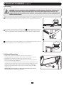
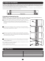
Y
a
NT ION for Lite nty
A
y
T
R A da ripp arra
AR STR e to EE T m/w
W I lin FR .co
G on a te
REister win ippli
Owner’s Manual
g to .tr
Re ce ww
an t w
ch duc
o
pr
18U SmartRack™ Enclosure
Model: SR18UB
Table of Contents
1. Important Safety Instructions
2
2. Overview
2
3. Feature Identification
3
4. Enclosure Installation
4.1 Preparation
4.2 Unpacking
4.3 Installing Casters and Levelers
4.4 Placement
4.5 Leveling the Enclosure
4.6 Ground Connection
4
4
4
4
4
5
5
5. Enclosure Configuration
5.1 Door Locks
5.2 Reversing the Doors
5.3 Mounting Rails
5.4 Adjusting Mounting Rail Depth
6
6
6
6
6
6. Equipment Installation
6.1 Installing or Removing Cage Nuts
7
7
7. Specifications
7
8. Storage and Service 8
9. Warranty & Warranty Registration 8
Español9
Français17
1111 W. 35th Street, Chicago, IL 60609 USA • www.tripplite.com/support
Copyright © 2012 Tripp Lite. All trademarks are the sole property of their respective owners.
1. Important Safety Instructions
SAVE THESE INSTRUCTIONS
This Manual contains instructions and warnings that must be followed during the installation and operation of the product described in this manual. Failure to
comply may invalidate the warranty and cause property damage or personal injury.
• Keep the enclosure in a controlled indoor environment, away from moisture, temperature extremes, flammable liquids and gasses, conductive
contaminants, dust and direct sunlight.
• Leave adequate space at the front and rear of the enclosure for proper ventilation. Do not block, cover or insert objects into the external ventilation
openings of the enclosure.
• The enclosure is extremely heavy. Use caution when handling the enclosure. Do not attempt to unpack, move or install it unassisted. Use a
mechanical device such as a forklift or pallet jack to move the enclosure in the shipping container.
• Do not place any object on the enclosure, especially containers of liquid, and do not attempt to stack the enclosures.
• Inspect the shipping container and the enclosure for shipping damage. Do not use the enclosure if it is damaged.
• Leave the enclosure in the shipping container until it has been moved as close to the final installation location as possible.
• Install the enclosure in a structurally sound area capable of handling the load, or on a level floor that is able to bear the weight of the enclosure, all
equipment that will be installed in the enclosure and any other enclosures and/or equipment that will be installed nearby.
• Use caution when cutting packing materials. The enclosure could be scratched, causing damage not covered by the warranty.
• Save all packing materials for later use. Repacking and shipping the enclosure without the original packing materials may cause product damage
that will void the warranty.
• Do not reship the enclosure with additional equipment unless the enclosure was shipped with a special shock pallet (“SP1” models only). The
combined weight of the enclosure and installed equipment must not exceed the load capacity of the pallet. Tripp Lite is not responsible for any
damage that occurs during reshipment.
• The casters are designed for minor position adjustments within the final installation area only. The casters are not designed for moving the
enclosure over longer distances.
• When rolling the enclosure on its casters, always push it from behind; never pull it toward you.
• A rolling enclosure can cause personal injury and property damage if not properly supervised. If rolling the enclosure down a ramp is required, use
extreme caution. Do not attempt to use ramps that have a slope steeper than 1:12.
• Use of this equipment in life support applications where failure of this equipment can reasonably be expected to cause the failure of the life support
equipment or to significantly affect its safety or effectiveness is not recommended. Do not use this equipment in the presence of a flammable
anesthetic mixture with air, oxygen or nitrous oxide.
2. Overview
SmartRack Enclosures accommodate all standard 19-inch rackmount equipment, regardless of vendor, and ship fully assembled for quick and easy
deployment.
2
3. Feature Identification
1
2
3
4
5
6
7
8
Locking/Reversible Front Door
Locking/Reversible Back Door
Horizontal Rails
Vertical Mounting Rails
Vents
Locking/Removable Side Panels
Casters
Leveling Feet
5
2
6
4
3
4
6
1
7
8
3
4. Enclosure Installation
Caution! Read All Instructions and Warnings Before Installation!
Warning: Rack enclosures can be extremely heavy. Do not attempt to unpack, move or install the enclosure without assistance. Use
extreme caution when handling the enclosure and be sure to follow all handling and installation instructions. Do not attempt to install
equipment without first stabilizing the enclosure.
4.1 Preparation
The enclosure must be installed in a structually sound area that is able to bear the weight of the enclosure, all the equipment that will be installed in the
enclosure and any other enclosures and/or equipment that will be installed nearby. Before unpacking the enclosure, you should transport the shipping
container closer to the final installation location to minimize the distance you will need to move the unit after the protective packaging has been
removed. If you plan to store the enclosure for an extended period before installation, follow the instructions in the Storage and Service section.
You need several tools:
• 14 mm Open-End or Combination Wrench
• Level
• 10 mm Open-End or Combination Wrench (2)
• Phillips-Head Screwdriver
4.2 Unpacking
Use at least two people to unpack the enclosure.
1 M
ove
shipping pallet to a firm, level surface.
all packing materials for later use unless you are certain they will not be required. Packing materials are recyclable.
3 With one person on each side, carefully lift the enclosure off of the pallet and place on a firm, level surface.
4 Examine the enclosure for any damage or loose parts. Confirm all parts are present. If anything is missing or damaged, contact Tripp Lite for
assistance. Do not attempt to use the enclosure if it has been damaged.
2 S
ave
4.3 Installing Casters and Levelers
1
Installing Casters
Tripp Lite’s accessory SRCASTER kit is included with your rack enclosure. This kit consists of 4
casters with required locknuts, washers and bolts for installation. Using two 10 mm open-end or
combination wrenches, install the casters to the base of the unit using the pre-drilled holes near
each
corner of the enclosure.
1
2
Installing Levelers
There are 4 levelers included with your rack enclosure, 2 for the front and 2 for the rear. Using a 14
mm open-end wrench, install the levelers at the base of the unit using the threaded holes near
each corner of the enclosure by turning the leveler in counter-clockwise. When the rack enclosure is
moved to its installation location, use a 14mm open-end wrench to level the rack.
2
4.4 Placement
You can use the casters to move the enclosure for a short distance over a level, smooth, stable surface by pushing it from the front or rear (not the
side panels). Do not attempt to roll the enclosure over long distances. The enclosure should be moved close to its installation location inside its
shipping container before it is unpacked. Warning: Use appropriate equipment and follow all applicable safety procedures and regulations.
Warning: Never attempt to lift or install without adequate help.
Do not try lifting the enclosure alone.
4
4. Enclosure Installation
(continued)
4.5 Leveling
WARNING: Level the enclosure before attempting to install equipment. Install the enclosure in a
structurally sound area with a level floor that is able to bear the weight of the enclosure, all
equipment that will be installed in the enclosure and any other enclosures and/or equipment that
will be installed nearby.
1 A
fter
the enclosure has been moved to the installation location, use a carpenter's level to check
the slope of the floor. If the floor slopes more than 1%, choose an alternate installation site.
1
FLOOR
a 14 mm open-end wrench to lower each leveler A until it reaches the floor. (There are 4
levelers, 2 at the front and 2 at the rear.) Make sure each leveler contacts the floor solidly.
Note: Lower a leveler by turning it clockwise; raise a leveler by turning it counter-clockwise.
2 U
se
A
2
3 A
fter
lowering each leveler, use the carpenter's level to confirm that the enclosure is level in all
directions. Adjust the levelers as required until the enclosure is level.
3
4.6 Ground Connection
• All parts of the enclosure are grounded to the frame of the enclosure.
• Grounding studs have been provided in all four corners of the enclosure to allow for
grounding in any configuration (including front or back door reversals).
• Grounding holes are also provided on top and bottom corners of both front and back
doors to accommodate any configuration.
• To ground the enclosure simply connect the two quick-disconnect grounding wires, one
to the hole provided on the inside of either the front or back door and the other to the
stud provided in any corner of the enclosure. Connect your facility’s earth ground
connection to the grounding stud not used by door connections, using an 8 AWG
(3.264 mm) wire.
Warning: Attach each enclosure to earth ground separately. Do not use the
enclosure without an earth ground connection.
5
EARTH
GROUND
5. Enclosure Configuration
5.1 Door Locks
The front and back doors have locks that are accessible by the included keys.
Each side panel locks using an L-shaped lever on the inside of the enclosure.
1 To
unlock and remove the side panels, lift the shorter leg of the “L” up and pull it away from the side panel. Pull the tab on the side panel and
remove it from the enclosure.
2 To re-lock the side panels, secure it in the proper position, lift the shorter leg of the “L” up and push it toward the side panel, back into the hole that it was
in initially. Once it is in place, push the shorter leg of the “L” down to lock it. Note: To lock and unlock the side panels, you will need to have access to the
interior of the enclosure.
A
B
B
A
1
2
5.2 Reversing the Doors
The doors of the enclosure are held in position on the enclosure’s frame with two spring-loaded pins. To reverse the door’s swing direction, simply
release the pins by pulling them up (lower pin) or down (upper pin) and remove them from the mounting holes on the frame of the enclosure.
Flip the door in the opposite direction and replace the pins in the identical mounting holes on the other side of the enclosure’s frame by lining them up
with the mounting holes and engaging them again.
5.3 Mounting Rails
The enclosure comes with mounting rails that have square holes for mounting rack equipment. To
install equipment, use the included cage nuts and other hardware. (See page 7 for installation of
cage nuts.) Warning: Be sure to have the enclosure in its final position on the floor before
mounting any equipment inside. Also be sure to have all the right adjustments on your rails
before mounting equipment. (See below for Adjusting Mounting Rail Depth.)
5.4 Adjusting Mounting Rail Depth
Warning: Do not attempt to adjust rails while equipment is installed in the enclosure.
Do not attempt to use rails without screws installed. (2 per rail.)
The 4 mounting rails are pre-installed to accommodate equipment with a mounting depth of 20.5
inches (521 mm). Do not adjust the mounting rails unless your equipment requires a different
mounting depth. The front and rear sets of rails can be adjusted independently for mounting of
equipment with depths between 3 inches (76 mm) and 32.5 inches (826 mm).
rail is connected to the enclosure with 2 screws and 2 cage nuts: 1 set in the upper
corner and another in the lower corner. Using a Phillips-head screwdriver, remove the screws
that fasten the rails to the enclosure.
2 Move cage nuts to desired depth and reinstall.
3 Slide the mounting rails to the desired depth and reattach them using the screws you removed
in Step 1.
2
1 E
ach
1
3
6
29
6. Equipment Installation
28
28
27
27
Warning: Do not install equipment
until you have stabilized the enclosure. Install heavier equipment first and install
it towards the bottom
of the enclosure. Install equipment starting from the bottom of the enclosure and proceeding toward the top of the enclosure - never the
reverse. If using sliding equipment rails, be careful when extending the rails. Do not extend more than one set of sliding equipment rails
26
26
at one time. Avoid extending
sliding equipment rails near the top of the enclosure.
Note: The square holes in the middle of each rack unit are numbered and also include a small notch to aid identification. A single rack unit includes the space
occupied by the numbered hole and the holes directly above and below.
25
25
24
24
2
23
1 Rack Unit
23
6.1 Installing or Removing Cage Nuts
22
22
WARNING: The flanges of the cage nuts should engage the sides of the square opening in the rail, not the top and bottom. Follow the
instructions in your equipment
documentation to ensure proper installation of your equipment.
21
21
22
1 Locate
the numbered square openings in the mounting rails where you plan to install your
equipment. You will install cage nuts (included) into the square openings in order to provide an
attachment point for the20 mounting screws (included). Note: Consult your equipment
documentation to determine how many cage nuts will be required and where they will need to
be installed.
20
21
22
19
19
1
18
18
2 From
the inside of the mounting rail, insert one of the flanges of the cage nut through the
square opening. Press it against the side of the square opening. Each flange should engage one
side of the square opening, not the top or bottom.
20
21
19
22
18
20
2
3 C
ompress
the cage nut at the sides slightly to allow the remaining flange to fit through the
square opening. When the cage nut is properly installed, both flanges will protrude through the
square opening and will be visible on the outer surface of the mounting rail. Repeat steps 1-3
until all required cage nuts are installed.
21
19
22
20
18
3
4 After
installing the required cage nuts, use the included mounting screws and cup washers to
secure your equipment to the rack rail. Place the cup washers between the screws and the
equipment mounting brackets.
21
19
Note: Your equipment may also include mounting hardware. Read the mounting instructions that came
with your equipment before installing your equipment.
20
18
To Remove Cage Nuts, Reverse Steps 1-3
Note: You may wish to use a cage nut tool (user-supplied) to aid cage nut installation and removal.
4
7. Specifications
19
18
Model
SR18UB
Dimensions (H x W x D)
35.6 x 23.63 x 33.5” (905 x 600 x 850 mm)
Unit Weight
105 lb (48 kg)
Load Capacity
500 lb (226 kg) Stationary or Rolling
Mounting Depth (Adjustable)
3” to 32.5” (76 to 826 mm)
7
6. Operation
(continued)
8. Storage and Service
Storage
The enclosure should be stored in a controlled indoor environment, away from moisture, temperature extremes, flammable liquids and gasses,
conductive contaminants, dust and direct sunlight. Store the enclosure in its original shipping container if possible.
Service
Your Tripp Lite product is covered by the warranty described in this manual. A variety of Extended Warranty and On-Site Service Programs are also
available from Tripp Lite. For more information on service, visit www.tripplite.com/support. Before returning your product for service, follow these steps:
1. Review the installation and operation procedures in this manual to insure that the service problem does not originate from a misreading of the
instructions.
2. If the problem continues, do not contact or return the product to the dealer. Instead, visit www.tripplite.com/support.
3. If the problem requires service, visit www.tripplite.com/support and click the Product Returns link. From here you can request a Returned Material
Authorization (RMA) number, which is required for service. This simple on-line form will ask for your unit’s model and serial numbers, along with
other general purchaser information. The RMA number, along with shipping instructions will be emailed to you. Any damages (direct, indirect, special
or consequential) to the product incurred during shipment to Tripp Lite or an authorized Tripp Lite service center is not covered under warranty.
Products shipped to Tripp Lite or an authorized Tripp Lite service center must have transportation charges prepaid. Mark the RMA number on the
outside of the package. If the product is within its warranty period, enclose a copy of your sales receipt. Return the product for service using an
insured carrier to the address given to you when you request the RMA.
9. Warranty and Warranty Registration
5-Year Limited Warranty
Seller warrants this product, if used in accordance with all applicable instructions, to be free from original defects in material and workmanship for a
period of 5 years from the date of initial purchase. If the product should prove defective in material or workmanship within that period, Seller will repair
or replace the product, at its sole discretion.
THIS WARRANTY DOES NOT APPLY TO NORMAL WEAR OR TO DAMAGE RESULTING FROM ACCIDENT, MISUSE, ABUSE OR NEGLECT. SELLER MAKES
NO EXPRESS WARRANTIES OTHER THAN THE WARRANTY EXPRESSLY SET FORTH HEREIN. EXCEPT TO THE EXTENT PROHIBITED BY APPLICABLE LAW,
ALL IMPLIED WARRANTIES, INCLUDING ALL WARRANTIES OF MERCHANTABILITY OR FITNESS, ARE LIMITED IN DURATION TO THE WARRANTY PERIOD
SET FORTH ABOVE; AND THIS WARRANTY EXPRESSLY EXCLUDES ALL INCIDENTAL AND CONSEQUENTIAL DAMAGES. (Some states do not allow
limitations on how long an implied warranty lasts, and some states do not allow the exclusion or limitation of incidental or consequential damages, so
the above limitations or exclusions may not apply to you. This warranty gives you specific legal rights, and you may have other rights which vary from
jurisdiction to jurisdiction).
WARNING: The individual user should take care to determine prior to use whether this device is suitable, adequate or safe for the use intended. Since
individual applications are subject to great variation, the manufacturer makes no representation or warranty as to the suitability or fitness of these
devices for any specific application.
Warranty Registration
Visit www.tripplite.com/warranty today to register the warranty for your new Tripp Lite product.You’ll be automatically entered into a drawing for a
chance to win a FREE Tripp Lite product!*
* No purchase necessary. Void where prohibited. Some restrictions apply. See website for details.
Tripp Lite has a policy of continuous improvement. Specifications are subject to change without notice.
1111 W. 35th Street, Chicago, IL 60609 USA • www.tripplite.com/support
8
Manual del propietario
Rack SmartRack™ 18U
Modelo: SR18UB
Índice
1. Instrucciones de seguridad
importantes
10
2. Generalidades
10
3. Identificación de las características 11
4. Instalación del rack
12
4.1 Preparación
12
4.2 Desembalaje
12
4.3 Instalación de Ruedas y Niveladores 12
4.4 Ubicación
12
4.5 Nivelación del rack
13
4.6 Conexión a tierra
13
5. Configuración del rack
5.1 Cerraduras de las puertas
5.2 Cómo invertir las puertas
5.3 Rieles de montaje
5.4 Ajuste de la profundidad del riel
de montaje
14
14
14
14
6. Instalación de equipos
6.1 Instalación o extracción de las
tuercas de jaula
7. Especificaciones
15
8. Almacenamiento y servicio
16
9. Garantía
16
14
15
15
English1
Français17
1111 W. 35th Street, Chicago, IL 60609 USA • www.tripplite.com/support
Copyright © 2012 Tripp Lite. Todas las otras marcas registradas son propiedad de sus respectivos dueños.
1. Instrucciones de seguridad importantes
GUARDE ESTAS INSTRUCCIONES
Este manual contiene instrucciones y advertencias que deben seguirse durante la instalación y operación de este producto descriptas en este manual. El
incumplimiento invalidará la garantía, pudiendo causar serios daños a la propiedad y/o lesiones personales.
• Mantenga el rack en un ambiente interior controlado, lejos de la humedad, las temperaturas extremas, los líquidos y los gases inflamables, los
contaminantes conductores, el polvo y la luz directa del sol.
• Deje espacio suficiente en el frente y la parte trasera del rack para una ventilación adecuada. No bloquee, cubra ni inserte objetos en las aberturas
de ventilación externa del rack.
• El rack es extremadamente pesado. Manipúlelo con precaución. No intente desembalarlo, moverlo ni instalarlo sin ayuda. Utilice un dispositivo
mecánico como una horquilla elevadora o un gato para pálets para moverlo en el contenedor de envío.
• No coloque ningún objeto sobre el rack, especialmente contenedores de líquido, y no intente apilar los racks.
• Inspeccione el contenedor de envío y el rack para detectar daños producidos durante el transporte. No lo use si está dañado.
• Deje el rack en el contenedor de envío hasta que se lo haya movido lo más cerca posible del lugar de instalación.
• Instale el rack en una zona estructuralmente sana, capaz de soportar la carga, con piso nivelado que pueda soportar su peso, el de todos los
equipos que se instalarán en él y cualquier otro rack o equipos que se instalarán cerca.
• Corte el material de embalaje con precaución. El rack podría rayarse causando daños que no están cubiertos por la garantía.
• Guarde los materiales de embalaje para utilizarlos en el futuro. Si el rack se vuelve a embalar y a enviar sin los materiales de embalaje originales,
se pueden causar daños que anularán la garantía.
• No vuelva a enviar el rack con equipos adicionales, a menos que haya sido enviado con un pálet especial contra golpes (sólo los modelos “SP1”).
El peso combinado del rack y de los equipos instalados no debe exceder la capacidad de carga del pálet. Tripp Lite no se responsabiliza por ningún
daño que se produzca durante el reenvío.
• Las ruedas están diseñadas para realizar únicamente ajustes menores de la posición dentro de la zona de instalación final. No están destinadas a
mover el rack en largas distancias.
• Cuando lo haga rodar sobre sus ruedas, empújelo siempre desde atrás, nunca hacia usted.
• Un rack rodante puede causar lesiones personales y daño a la propiedad si no se supervisa correctamente. Si es necesario hacerlo rodar por una
rampa, hágalo con precaución extrema. No intente usar rampas con una pendiente más pronunciada que 1:12.
• No se recomienda usar este equipo en aplicaciones de mantenimiento artificial de la vida, donde se puede esperar razonablemente que su falla
cause la falla del equipo de mantenimiento de la vida o que afecte de manera importante su seguridad o eficiencia. No use este equipo en
presencia de mezclas anestésicas inflamables con aire, oxígeno u óxido nitroso.
2. Generalidades
Los racks SmartRack sirven para colocar cualquier equipo estándar para montar en rack de 19 pulgadas, independientemente del proveedor, y se
envían completamente ensamblados para una implementación rápida y fácil.
10
3. Identificación de las características
1
2
3
4
5
6
7
8
Puerta frontal con cerradura/reversible
Puerta trasera con cerradura/reversible
Rieles horizontales
Rieles de montaje verticales
Ventilación
Paneles laterales con cerradura/desmontables
Ruedas
Pie de nivelado
5
2
6
4
3
4
6
1
7
8
11
4. Instalación del rack
¡Precaución! Lea todas las instrucciones
y advertencias antes de la instalación.
Advertencia: Los racks pueden ser extremadamente pesados. No intente desembalarlo, moverlo ni instalarlo sin ayuda. Use máxima
precaución al manipularlo y asegúrese de seguir todas las instrucciones de manipulación e instalación. No intente instalar equipos sin
estabilizar primero el rack.
4.1 Preparación
El rack se debe instalar en una zona estructuralmente sana que pueda soportar su peso, el de todos los equipos que se instalarán en él y cualquier
otro rack o equipos que se instalarán cerca. Antes de desembalar el rack, debería transportar el contenedor de envío lo más cerca posible de la
ubicación de instalación final para minimizar la distancia que necesitará moverlo después de quitarle el embalaje protector. Si planea almacenarlo
durante un período prolongado antes de instalarlo, siga las instrucciones de la sección Almacenamiento y servicio.
Necesitará algunas herramientas:
• Llave de boca o de combinación de 14 mm
• Nivel
• Llave de boca o de combinación de 10 mm (2)
• Destornillador Philips
4.2 Desembalaje
Utilice al menos dos personas
para desembalar el rack.
1 M
ueva
el pálet de envío hacia una superficie firme y nivelada.
todos los materiales de embalaje para uso futuro, a menos que esté seguro de que no serán necesarios. Los materiales de embalaje son
reciclables.
3 Con una persona de cada lado, eleve el rack con cuidado hacia afuera del pálet y colóquelo en una superficie firme y nivelada.
4 Examine el rack para detectar daños o partes sueltas. Confirme que estén todas las partes. Si algo falta o está dañado, comuníquese con
Tripp Lite para obtener ayuda. No use el rack si está dañado.
2 G
uarde
4.3 Instalación de Ruedas y Niveladores
1 I nstalación
de Ruedas
Se incluye el kit de accesorios SRCASTER de Tripp Lite con el rack. El SRCASTER Kit se compone
de 4 ruedas con las contratuercas, arandelas y pernos adecuados para la instalación. Utilice dos
llaves de extremo abierto o de combinación de 10 mm, instale las ruedas en la base de la unidad
usando los orificios taladrados previamente cerca de cada esquina del rack.
2 I nstalación
1
de Niveladores
Hay 4 niveladores incluidos con su rack, 2 para el frente y 2 para la parte trasera. Utilizando una
llave de boca de 14 mm, instale los niveladores en la base de la unidad usando los orificios
roscados cerca de cada esquina del rack girando los niveladores en sentido contrario al de las
manecillas del reloj. Cuando el rack se mueva a su lugar de instalación, use una llave de boca de
14 mm para nivelar el rack.
2
4.4 Ubicación
Puede utilizar las ruedas para mover el rack una distancia corta sobre una superficie nivelada, lisa y estable empujándolo desde adelante o atrás (no
desde los paneles laterales). No intente hacerlo rodar por distancias largas. Antes de desembalarlo, el rack se debe mover hasta cerca del sitio de
instalación dentro de su contenedor de envío. Advertencia: Use los equipos adecuados y siga todos los procedimientos y reglamentaciones
de seguridad correspondientes.
Advertencia:
Nunca intente elevar o instalar el rack sin la ayuda adecuada.
No intente elevar el rack usted solo.
12
4. Instalación del rack
(continuación)
4.5 Nivelación del rack
ADVERTENCIA: Nivele el rack antes de instalar los equipos. Instale el rack en una zona
estructuralmente sana, con piso nivelado que pueda soportar su peso, el de todos los equipos
que se instalarán en él y cualquier otro rack o equipos que se instalarán cerca.
1 D
espués
de mover el rack a la ubicación de instalación, utilice un nivel de carpintero para
verificar la pendiente del suelo. Si es mayor al 1%, elija un sitio de instalación alternativo.
1
SUELO
2 U
se
una llave de boca de 14 mm para bajar cada nivelador A hasta que llegue al piso. (Hay 4
niveladores, 2 en el frente y 2 atrás). Asegúrese de que cada uno apoye con firmeza sobre el
piso. Nota: Baje un nivelador girándolo en sentido horario; súbalo girándolo en sentido
antihorario.
A
2
3 D
espués
de bajar cada nivelador, use el nivel de carpintero para confirmar que el rack está
nivelado en todas las direcciones. Ajuste los niveladores hasta que el rack esté nivelado.
3
4.6 Conexión a tierra
• Todas las partes del rack se deben conectar a tierra al marco del rack.
• Se proporcionan pernos de conexión a tierra en las cuatro esquinas del rack para permitir
la conexión a tierra en cualquier configuración (incluidas las puertas frontal y trasera
reversibles).
• También se proporcionan orificios para conexión a tierra en las esquinas inferiores y
superiores de las puertas frontal y trasera para lograr cualquier configuración.
• Para conectar el rack a tierra, sólo conecte los dos cables de conexión a tierra de
desconexión rápida, uno en el orificio del interior de la puerta frontal o trasera, y el otro
en el perno de cualquiera de las esquinas del rack. Conecte la conexión a tierra de la
instalación en el perno de conexión a tierra no utilizado por las conexiones de las
puertas utilizando un cable 8 AWG (3,264 mm).
Advertencia: Conecte cada rack a tierra por separado. No use el rack sin una
conexión a tierra.
13
EARTH
GROUND
5. Configuración del rack
5.1 Cerraduras de las puertas
La puertas frontal y posterior tienen cerraduras que son accesibles con las llaves incluidas.
Cada panel lateral se asegura usando una palanca en L en el lado interno del gabinete.
1 Para desasegurar y desmontar los paneles laterales, levante el lado corto de la "L" y retírela del panel lateral. Jale la pestaña en el panel lateral y
desmóntela del gabinete.
2 Para colocar nuevamente los paneles laterales, asegúrelos en la posición correcta, levante el lado corto de la "L" y presionela hacia el panel lateral,
nuevamente al orificio en donde estaba inicialmente. Una vez en su sitio, oprima el lado corto de la "L" para asegurarla. Nota: Para asegurar y desasegurar
los paneles laterales, usted necesitará tener acceso al interior del gabinete.
A
B
B
A
1
2
5.2 Cómo invertir las puertas
Las puertas del rack se articulan en su posición en el marco del rack con dos clavijas a resorte. Para invertir la dirección de giro de la puerta, afloje las
clavijas tirando hacia arriba (clavija inferior) o hacia abajo (clavija superior) y extráigalas de los orificios de montaje en el marco del rack.
Gire la puerta en la dirección opuesta y vuelva a colocar las clavijas en los mismos orificios de montaje del otro lado del marco del rack, alineándolas
con los orificios de montaje y volviéndolas a colocar.
5.3 Rieles de montaje
El rack viene con rieles de montaje que poseen orificios cuadrados para montar los equipos del
rack. Para instalar los equipos, utilice las tuercas de jaula y las otras herramientas incluidas.
(Consulte la página 7 para ver la instalación de las tuercas de jaula). Advertencia: Asegúrese de
que el rack se encuentre en la posición final en el suelo antes de montar cualquier equipo
en el interior. Asegúrese también de realizar todos los ajustes adecuados de rieles antes
de montar los equipos. (Consulte la sección siguiente para ver el Ajuste de la profundidad
del riel de montaje).
5.4 Ajuste de la profundidad del riel de montaje
Advertencia: No intente ajustar los rieles mientras los equipos están instalados en el rack.
No intente utilizar rieles sin tornillos instalados. (2 por riel).
Los 4 rieles de montaje están preinstalados para acomodar los equipos con una profundidad de
montaje de 20,5 pulgadas (521 mm). No ajuste los rieles de montaje a menos que los equipos
requieran una profundidad de montaje distinta. Los conjuntos de rieles frontales y traseros pueden
ajustarse en forma independiente para montar equipos con profundidades entre 3 pulgadas (76 mm)
y 32,5 pulgadas (826 mm).
1 Cada
riel está conectado al gabinete con 2 tornillos y 2 tuercas de fijación: 1 juego en la esquina superior y otro en la esquina inferior. Usando un desatornillador Phillips, retire los tornillos que sujetan los rieles al gabinete..
2 Mueva
2
1
las tuercas de fijación a la profundidad deseada y reinstale.
3 Deslice
los rieles de montaje hasta la profundidad deseada y vuelva a unirlos mediante los
tornillos que extrajo anteriormente en el Paso 1.
14
3
28
28
6. Instalación de equipos
27
27
Advertencia: No instale equipos hasta que haya estabilizado el rack. Instale primero los equipos más pesados en la parte inferior del
rack. Instálelos de abajo hacia arriba, nunca en sentido contrario. Si usa rieles para equipos deslizantes, tenga cuidado al extender los
26
rieles. No extienda más de
un juego de rieles por vez. Evite extender rieles de equipos deslizantes cerca de la 26p