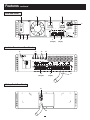
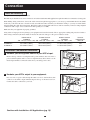
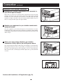
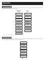
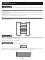
1
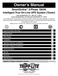
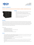
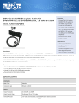
Owner’s Manual
SmartOnline
™
Tower/Rackmount Power Protection
SU6000RT3UPM • SU10KRT3UPM
Tower/Rackmount UPS Systems
SU6000XFMR • SU10KXFMR
Tower/Rackmount Isolation Transformers
BP240V7RT3U • BP240V10RT3U
Tower/Rackmount Battery Packs
Important Safety Warnings
2
Mounting
3
Features
6
Connection
9
Operation
13
Service/Warranty and Insurance
16
Specifications
17
Español/Français/Deutsch
18/35/52
1111 W. 35th Street • Chicago, IL 60609 USA
Customer Support: (773) 869-1234 • Application Services: (773) 869-1236
www.tripplite.com
Copyright ©2002 Tripp Lite. All rights reserved.
Important Safety Warnings
SAVE THESE INSTRUCTIONS. This manual contains important instructions and warnings that should be followed during the installation
and maintenance of all Tripp Lite SmartOnline Rackmount UPS Systems and their batteries.
UPS Location Warnings
• Install your UPS indoors, away from excess moisture or heat, direct sunlight, dust and conductive contaminants.
• Install your UPS in a structurally sound area. Your UPS is extremely heavy; take care when moving and lifting the unit.
• Only operate your UPS at indoor temperatures between 32° F and 104° F (between 0° C and 40° C). For best results, keep indoor
temperatures between 62° F and 84° F (between 17° C and 29° C).
• Leave adequate space around all sides of the UPS for proper ventilation: 12 in. (30 cm.) clearance at the rear; 4 in. (10 cm.) at sides
and on top.
• Do not install the UPS near magnetic storage media, as this may result in data corruption.
UPS Connection Warnings
• The power supply for this unit must be single phase rated in accordance with the equipment nameplate. It also must be suitably grounded.
Equipment Connection Warnings
• Do not use Tripp Lite UPS Systems in life support applications in which a malfunction or failure of a Tripp Lite UPS System could
cause failure or significantly alter the performance of a life support device.
• Connect your UPS’s and/or isolation transformer’s grounding terminal to a grounding electrode conductor.
• The UPS is connected to a DC energy source (battery). The output terminals may be live when the UPS is not connected to an AC supply.
Maintenance Warnings
• Your UPS, transformer and battery pack(s) do not require routine maintenance. Do not open them for any reason. There are no
user-serviceable parts inside.
Battery Warnings
• Do not operate your UPS without connecting it to an external battery pack.
• Connect only Tripp Lite battery packs to your UPS’s external battery connector.
• The batteries in your battery pack are recyclable. Refer to local codes for disposal requirements, or if in the USA call
1-800-SAV-LEAD (1-800-728-5323) for complete recycling information. CAUTION: Do not dispose of the batteries in a fire, as this
could cause the battery to explode.
• Because the batteries present a risk of electrical shock and burn from high short-circuit current, batteries should be changed only by
trained service personnel observing proper precautions. Consult your battery pack manual before proceeding. Remove watches, rings,
and other metal objects. Use tools with insulated handles. Wear rubber gloves and boots. Do not lay tools or metal parts on top of the
batteries. Do not short or bridge the battery terminals with any object. Disconnect the charging source prior to connecting or
disconnecting battery terminals. Determine if the batteries are inadvertently grounded. If inadvertently grounded, remove the source
of the ground. Contact with any part of a grounded battery can result in electrical shock. The likelihood of such shock will be
reduced if such grounds are removed during installation and maintenance.
• Do not open or mutilate the batteries. Released electrolyte is harmful to the skin and eyes, and may be toxic.
• Fuses should be replaced only by factory authorized personnel. Blown fuses should be replaced only with fuses of the same number
and type.
• Service and repair should be done only by trained personnel. During any service work to the UPS, it should be turned off or manually
bypassed via the transformer (see pg. 6-7). Note that potentially lethal voltages exist within this unit as long as the battery supply
is connected.
• Do not connect or disconnect battery pack(s) while the UPS is operating from the battery supply or when the transformer is not in
bypass mode.
• During “hot-swap” battery pack replacement (when the transformer is on manual bypass and connected equipment is turned ON)
your UPS will be unable to provide battery backup in the event of a blackout.
2
Mounting
Your equipment may be rackmounted in 4-post rack enclosures using the included rack shelves and the following suggested mounting
procedures, which should be used instead of the procedures described in your Owner's Manual (if any). These procedures are for common
enclosure types and may not be appropriate for all rack enclosures. You must determine the fitness of rackmount hardware and procedures
before mounting. If this hardware or these procedures are not suitable for your application, contact your rack enclosure's manufacturer for
a solution.
Mount one piece of equipment in a 4-post rack section using the Single Unit Installation procedure, or one piece of equipment in a 2-post
rack using the 2-Post (Telecom) Installation procedure. If you have two UPSRMRII shelf kits and a sufficiently deep rack, you may mount
two pieces of equipment in a 4-post rack section using the Back to Back Installation procedure.
Single Unit Installation
1
Connect the two segments of each shelf (A) using the included screws and nuts (B).
Leave the screws slightly loose so that the shelves can be adjusted in the next step.
B
A
1
2
Adjust each shelf to fit your rack, then mount them in the lowest available space of
your rack with the screws, nuts and washers provided (C). Note that the support ledges
should face inward. Tighten the screws that connect the shelf segments (B).
C
B
2
3
Attach mounting ears (D) to the front mounting holes of your equipment (E) using the
screws provided (F). The ears should face forward.
E
D
3
4
Using an assistant if necessary, lift yourequipment and slide it onto the mounting
shelves. Attach your equipment to the rack by passing the screws, nuts and washers
provided (G) through its mounting ears andinto the rack rails.
G
4
3
F
Mounting
continued
Back-to-Back Installation
1 Connect the shelved sections from two UPSRMRII kits (A) to the unshelved sections
(B) using the included screws and nuts (C). Note: Two unshelved sections will be
left over. Leave the screws slightly loose so that the shelves can be adjusted in the
next step.
C
B
A
1
2 Adjust each shelf to fit your rack, then mount them in the lowest available space of
your rack with with the screws, nuts and washers provided (D). Note that the support
ledges should face inward. Tighten the screws that connect the shelf segments (C).
D
C
2
3 Attach mounting ears (E) to the front mounting holes of your equipment (F) using the
screws provided (G). The ears should face forward.
F
E
3
4 Using an assistant if necessary, lift your equipment and slide it onto the mounting
shelves. Attach your equipment to the rack by passing the screws, nuts and washers
provided (H) through its mounting ears and into the rack rails.
H
4
4
G
Mounting
continued
2-Post (Telecom) Installation
1
Mount the shelved sections (A) of your UPSRMRII kit on the back side of your rack.
Mount them in the lowest available space of your rack with with the screws, nuts and
washers provided (B). Note that the support ledges should face inward.
A
B
1
2
Attach mounting ears (C) to the front mounting holes of your equipment (D) using the
screws provided (E). The ears should face backward.
D
C
E
2
3
Using an assistant if necessary, lift your equipment and slide it onto the mounting
shelves. Attach your equipment to the rack by passing the screws, nuts and washers
provided (F) through its mounting ears and into the rack rails.
F
3
Suggested Tower Mount Installation
1
The UPS system is shipped with two sets of plastic feet (A) and extensions (B) that
can be used to tower mount the UPS, a battery pack, and either an isolation transformer
or a second battery pack.
Adjust the feet to a width of 10.25 inches (26 cm) for a UPS and battery pack, or
to a width of 15.375 inches (39 cm) for three units. Align the feet in your installation
area, approximately 10 inches (26 cm) apart. Have one or more assistants help you
place the units on their sides in the feet. The control panel of the UPS should be
the UPS’s upper corner and face outward. If you are installing a transformer, place
it between the UPS and its battery pack.
B
A
1
5
Features
Familiarize yourself with the location and function of the front and rear panel features before installing and operating your UPS.
11
UPS Front Panel Controls
10
9
8
7
6
12
12
1
2
3
4
5
The UPS Front Panel Controls can be rotated in its mounting to match your tower or rackmount installation. To rotate the controls, insert a
flathead screwdriver into the Access Slots (12) and gently lever the controls out. Taking care not to excessively twist or pull the cables
connecting the controls to the rest of the UPS, turn the controls to the desired orientation and reinsert them.
1. LCD DISPLAY: This backlit (16x2 character) dot matrix display indicates a wide range of UPS operating conditions and diagnostic
data. It also displays UPS settings and options when the UPS is in setup mode.
2. ON/MUTE BUTTON: Press this button and hold it until you hear a beep to turn the UPS system’s inverter ON. If the UPS’s battery
alarm is sounding, press this button to silence it.
3. SCROLL UP/EXIT SETUP BUTTON: This button allows you to browse through different options and power readings on the LCD
display. Momentarily pressing it causes the LCD screen to display a different power reading (see “Normal Operation”, pg. 12). Pressing
it and the “SCROLL DOWN” button together puts the UPS in setup mode, where this button is used to scroll through setup options
and to exit setup mode.
4. SCROLL DOWN/SELECT BUTTON: This button allows you to browse through different options and power readings on the LCD
display. Momentarily pressing it causes the LCD screen to display a different power reading (see “Operation”, pg. 12). Pressing it and
the “SCROLL UP” button together puts the UPS in setup mode, where this button is used to select setup options.
5. OFF BUTTON: Press this button until you hear a beep to turn the UPS system’s inverter OFF.
6. O/P (OUTPUT) LED: This green light will illuminate to indicate your UPS is supplying AC power to connected equipment.
7. DC/AC (INVERTER) LED: This green light will illuminate to indicate the UPS’s DC/AC inverter is activated.
8. BYPASS LED: This green light will illuminate when the UPS is providing filtered mains power without engaging its converter or
inverter. If this LED is lit, connected equipment will not receive battery power in the event of a blackout.
9. AC/DC (Converter) LED: This green light will illuminate to indicate the UPS’s AC/DC converter is charging the connected battery
pack(s).
10. BATTERY LED: This red light will illuminate when the UPS is discharging the battery to provide connected equipment with AC
power. An alarm will sound which can be silenced by pressing the “ON/MUTE” button. This LED will remain lit after the alarm is
silenced.
11. I/P (INPUT) LED: This green light will illuminate to indicate an AC input supply is present.
12. ACCESS SLOTS: To rotate the controls, insert a flathead screwdriver into these slots and gently lever the panel out. Taking care not
to excessively twist or yank the cables connecting the controls to the rest of the UPS, turn the controls to the desired orientation and
reinsert them.
6
Features
continued
UPS Rear Panel
7
6
5
4
3
ACC.
EXTERNAL BATTERY
INPUT 240VDC
AC OUTPUT BREAKER
G
L1
L2
L2
G
L1
L2
L2
AC INPUT BREAKER
CAUTION:
L1
G
DO NOT DISCONNECT
UNDER LOAD
L1
G
AC INPUT
AC OUTPUT
SU6000RT3UPM
Input: 200/208/220/230/240V~, 50/60Hz
29.1/27.9/26.4/25.3/24.2A
Output: 200/208/220/230/240V~, 50/60Hz
30/28.8/27.3/26.1/25A
Battery Input: 240V
EPO
RS-232
8
DRY CONTACT
9
C
10
1
(Output)
UL
, 21A
US
2
(Input)
Isolation Transformer Rear Panel
16
17
C
UL
15
14
US
SU6000XFMRRT3U
Series: AGSM6000SDRT3U
Output: 100/120/200/208/220/230/240V~
50/60Hz, 6000VA, 4200W
Input: 200/208/220/230/240V~
50/60Hz, 30A
OUTPUT BREAKER
AC TO UPS
BREAKER
TRANSFORMER
PROTECT
AC OUTPUT
208V
240V
AC INPUT
VOLTAGE SELECT
208
120V
120V
L1
L1
N
G
N
L2
L2T
L1
N
G
N
L2
L2T
L1
12
(Output)
L2
L2
G
11
(Input)
Battery Pack Rear Panel
18
19
7
208
AC TO UPS
AC FROM UPS
240
G
240
G
L2
L1
L2
L1
G
G
L2
L1
L2
L1
G
13
Features
continued
UPS Rear Panel
1. Output Terminal Block: Use these terminals to connect your UPS to your equipment or to the transformer’s UPS Connector. Unscrew
and remove the cover plate above the block for access.
2. Input Terminal Block: Use these terminals to connect your UPS to your utility power outlet or to the transformer’s UPS Connector.
Unscrew and remove the cover plate above the block for access.
3. External Battery Connector: Use this to connect one or more Tripp Lite Battery Packs to the UPS. Remove the cover plate for access.
The UPS will not operate without a connection to a charged battery pack. Refer to the Battery Pack owner’s manual for connection
instructions and safety warnings.
4. AC Input Breaker: One double-pole circuit breaker controls input power to the UPS.
5. AC Output Breaker: One double-pole circuit breaker controls output power from the UPS.
6. Exhaust Fan: This cools and ventilates the inside of the UPS.
7. Accessory Slot: Remove the small cover panel to install optional accessories to remotely control and monitor your UPS. Visit
Tripp Lite on the Web (www.tripplite.com) to learn about available SNMP, network management and connectivity products that may
be installed in this slot.
8. EPO (Emergency Power OFF) Port: This RJ11 modular jack can be connected to a user-supplied switch to enable remote emergency
shutdown. See Step 5 in “Connection,” pg. 10, for details.
9. RS-232 Communication Port: This female DB9 serial port may be used to connect your UPS to a workstation or server. It uses RS-232
protocol to communicate with a connected computer. It is used with Tripp Lite software and the included serial cable to monitor and
manage the UPS remotely over a network and to automatically save open files and shut down equipment during a blackout. See
“Connection,” pg. 10, for details.
10. Dry Contact Interface Port: This female DB9 port sends contact-closure signals to indicate line-fail and low-battery status. See
“Connection,” pg. 10, for details.
Isolation Transformer Rear Panel
11. Utility Input Terminal Block: Use these terminals to connect your transformer to utility power. Unscrew and remove the cover plate
above the block for access.
12. Equipment Output Terminal Block: Use these terminals to connect your equipment to the transformer. Unscrew and remove the
cover plate above the block for access.
13. UPS Connector: Connect your transformer to the UPS’s Input Terminal Block by running the wires through this UPS Connector.
14 Overtemperature Reset Breaker: This circuit breaker trips if the unit’s temperature climbs too high.
15. AC to UPS Breaker: One double-pole circuit breaker controls the transformer’s power output to the UPS.
16. Output Breaker: One triple-pole circuit breaker controls the transformer’s power output to connected equipment.
17. Manual Bypass Switch: This red and yellow dial is used to circumvent the UPS while still supporting connected equipment when
performing UPS maintenance or switching battery packs. While this switch is on BYPASS, the UPS will charge the batteries and connected equipment will receive filtered AC mains power, but the equipment will not receive battery power in the event of a blackout.
Before performing UPS maintenance or switching battery packs, turn this switch to BYPASS and the AC to UPS breaker off, then shut
down the UPS and disconnect it from the transformer (disconnection is not necessary when switching batteries). Since equipment will
not receive battery power in the event of a blackout if this switch is on BYPASS, you may want to swap in a second UPS if the first
requires lengthy service.
Battery Pack Rear Panel
18. Input Connector: Use this cable to daisy chain additional Battery Packs onto the first. Remove the cover panel for access. Refer to
the Battery Pack owner’s manual for connection instructions and safety warnings.
19. Output Cable: Use this cable to connect the Battery Pack to the UPS. The UPS will not operate without a connection to a charged
battery pack. Refer to the Battery Pack owner’s manual for connection instructions and safety warnings.
8
Connection
Notes on Hardwiring
Wiring must be done by a qualified electrician.
The UPS may be installed on its own or connected to an isolation transformer. Both applications require the UPS to be connected to a battery pack.
When making wiring connections, observe the cable connection regulations appropriate to your area [e.g. National Electrical Code (NEC)
in the U.S.] at all times. Be sure to install an easily accessible disconnect switch in your installation wiring so you may cut off the UPS’s
AC input during fires and other emergencies. Ensure that cables are fitted with cable sleeves and are secured by connector clamps. Tighten
connections with a torque of not less than 24-28 inch-pounds (2.7-3.2 NM).
Make sure that your equipment is properly grounded.
Using cables of improper size may damage your equipment and cause fire hazards. Choose appropriate cabling and protection circuits to
make wiring connections (Ground conductors must be the same size and type as the power conductors used):
SU6000RT3U
SU10KRT3U
RATED INPUT
RATED OUTPUT
CURRENT
CURRENT
200 - 240 (1Ø, 2-Wire + PE) 200 - 240V (1Ø, 2-Wire + PE)
30A 8 AWG (10mm2)
30A 8 AWG (10mm2)
50A 6 AWG (16mm2)
50A 6 AWG (16mm2)
RATED OUTPUT
CURRENT
120V (1Ø, 2-Wire + PE)
2 × 30A 8 AWG (10mm2)
2 × 50A 6 AWG (16mm2)
Installation—No Isolation Transformer
1
Hardwire your utility power source to your UPS’s input.
Remove the top of the box covering the UPS’s power terminals. Pass one end of a
power cable through the UPS’s cover box’s right knockout, then connect it to the
UPS’s input terminals. Connect the other end to your utility power source.
1
2
Hardwire your UPS’s output to your equipment.
Pass one end of a power cable through the UPS cover box’s left knockout, then
connect it to the UPS’s output terminals. Replace the top of the UPS cover box.
Connect the cable’s other end to your load.
2
Continue with Installation—All Applications (pg. 10)
9
OUTPUT
PROTECTION
CIRCUIT
30A
63A
Connection
continued
Installation—With Isolation Transformer
1
Hardwire your isolation transformer’s UPS connector to
your UPS’s input and output.
NORMAL
BY
PASS
Remove the tops of the boxes covering the UPS’s and transformer’s input and output
terminals. Pass the free end of the isolation transformer’s UPS connector through
the UPS’s cover box’s knockout, then connect it to the UPS’s input and output
terminals according to the labels on the wires and the terminals. Replace the top of
the box covering the UPS’s input and output terminals.
1
2
Hardwire your equipment to your isolation transformer’s
equipment output.
Pass your equipment’s power cable(s) through one of the transformer cover box’s
left knockouts, then connect them to the transformer’s equipment output terminals.
See the Output Voltage Diagram to determine which terminal connections will provide
which voltages.
NORMAL
BY
PASS
2
3
Select your input voltage. Hardwire your isolation
transformer’s utility input to your utility power source.
Place a jumper between the 208V or 240V voltage select terminals to set the transformer’s
input voltage. Connect one end of a power cable to your utility power source. Pass
the cable’s other end through one of the transformer cover box’s center knockouts,
then connect the cable to the utility input terminals. Replace the top of the transformer
cover box.
NORMAL
BY
PASS
3
AC OUTPUT VOLTAGE DIAGRAM
208V
240V
120V
Continue with Installation—All Applications (pg. 10)
10
120V
Connection
continued
Installation—All Applications
4
Connect external battery pack(s) to your UPS
Your UPS has no internal batteries and must be connected to at least one external
battery pack to operate. Complete installation and mounting instructions for your
battery pack(s) appear in the battery pack(s)’s owner’s manual. Make sure that
connection cables are fully inserted into their connectors. Small sparks may result
during battery pack connection; this is normal.
Your UPS will not operate unless connected to a charged external battery pack.
Battery packs are fully charged prior to shipping. However, if your battery pack has
been stored for an extended period, recharge its battery for 8 hours. To charge the
battery pack, turn on the UPS’s and isolation transformer’s AC input breakers. Your
UPS may not provide its full runtime if the battery pack is not fully charged.
4
Once the UPS is operating, it will charge its battery pack(s) automatically.
5
Connect communication cables to your UPS
(optional)
Connecting communications cables to your UPS is optional; your UPS will operate
properly without these connections.
NORMAL
To enable full network monitoring and control of the UPS, use the DB9 cable provided
to connect the UPS’s RS-232 port to a computer’s DB9 serial port. Install
Tripp Lite’s PowerAlert software onto the computer from the CD provided, or
download the most recent version of PowerAlert from www.tripplite.com.
BY
PASS
To send and receive basic contact closure signals to and from the UPS, use a contact
closure DB9 cable (user-supplied) to connect the UPS’s dry contact port to a computer’s
DB9 serial port. See the Dry Contact Interface Table and Diagram to decipher the
signals from this port, or install Tripp Lite’s PowerAlert software onto the computer
from the CD provided, or download the most recent version of PowerAlert from
www.tripplite.com.
5
To install an emergency power off switch, use a RJ11 cable (user-supplied) to connect
the EPO port to a remote switch. The pin assignments for the EPO port are shown
below. If there is a short between pins 2 and 3, 2 and 5, 4 and 5, or 3 and 4, the UPS
will power off.
DRY CONTACT INTERFACE DIAGRAM
DRY CONTACT INTERFACE TABLE
EPO PIN ASSIGNMENT
lm in. > 3.3 mA
LOW BATTERY
REMOTE SHUTDOWN SIGNAL
FROM EXTERNAL
BACK-UP
NO
NO
COM
COM
NC
NC
5 9 4 8 3 7 2 6 1
UPS Operating Pin 8,3 Pin 1,3 Pin 6,3
Mode
Normal
OPEN
OPEN
*
Back Up
CLOSE
*
*
Low Battery
CLOSE CLOSE
12V
X
1
2
3
*
4
1K
Fault
SIGNAL FROM COMPUTER
*
*
5
CLOSE
X
* Inactive: may be in either state
>2 sec
12 V
MAXIMUM CAPACITY OF DRY CONTACT: AC250V/3A • DC30V/3A
0
11
6
Connection
6
continued
Turn input to the UPS ON
If the UPS is connected to a transformer, turn the transformer’s UPS and Load
Breakers ON.
Turn the UPS’s Input Circuit Breaker ON.
Press the UPS’s ON button until you hear a beep to begin inverter operation.
If your AC input is not providing power normally, you may “cold start” your UPS
from battery. (Your battery must be at least partially charged for this operation to
succeed.) Press and hold the “ON” switch until you hear a beep to start your UPS
in “ON BATTERY” mode. Note that some electronic equipment may draw more
amps during startup; when starting from battery, consider reducing the initial load
on the UPS.
6
Your UPS will perform a brief self-test and show the results on the LCD Display.
See the Self-Test section, pg. 12, for the display sequence.
7
Configure your UPS’s output.
Put your UPS into bypass mode by holding the OFF button down until the UPS
beeps, then put your UPS into setup mode by holding down both of its scroll buttons at
once. Scroll through the setup options and select the appropriate setting for each of
the following options.
Output Voltage: Select 200, 208, 220, 230 or 240 VAC.
Output Frequency: Your UPS will autoselect 50 or 60 Hz to match the input.
Economy Mode: Your UPS can provide on-line operation with zero transfer time.
It can also operate in a more energy-efficient line-interactive mode. Select
Economy On to put the UPS in line-interactive mode. Select Economy Off to put
the UPS in on-line mode.
7
After you have set these options, exit the setup mode with the scroll buttons, then
exit bypass mode by holding the ON button down until you hear a beep.
8
Turn UPS output ON.
Turn the UPS’s Output Circuit Breaker ON.
If the UPS is connected to a transformer, turn the transformer’s Manual Bypass
Switch from BYPASS to NORMAL.
Your UPS will now provide power to connected equipment.
9
To turn the UPS and transformer OFF.
Press the UPS’s OFF button until you hear a beep. Your load will still be energized.
The inverter is now off, but your UPS is not fully deactivated. The LCD Display
will show “BYPASS MODE.”
Turn the UPS’s Input and Output Circuit Breakers OFF. If the UPS is connected to
a transformer, turn the transformer’s AC Input and Output Circuit Breakers OFF.
Your load will no longer be energized, and the LCD display will be dark.
12
8
Operation
Startup Self-Test
When you turn the UPS ON, it will enter Diagnostic Mode and perform a brief self-test lasting about 15 seconds. The results of the self-test
are shown on the LCD screen in the sequence below.
STARTED WITH
AC INPUT
COLD
START*
DIAGNOSTIC MODE
FREQ OUT = XXHz
DIAGNOSTIC MODE
FREQ OUT = XXHz
M
M
DIAGNOSTIC MODE
INPUT AC OK
DIAGNOSTIC MODE
INPUT AC BAD
M
M
DIAGNOSTIC MODE
INPUT AC OK
DIAGNOSTIC MODE
INPUT AC BAD
M
M
DIAGNOSTIC MODE
BATTERY OK
DIAGNOSTIC MODE
BATTERY OK
M
M
DIAGNOSTIC MODE
CHARGER OK
DIAGNOSTIC MODE
AC/DC OK
M
M
DIAGNOSTIC MODE
AC/DC OK
DIAGNOSTIC MODE
TESTING INVERTER
M
M
DIAGNOSTIC MODE
TESTING INVERTER
ON BATTERY MODE
LOAD = XXX% X.XXKW
M
ONLINE MODE
LOAD = XXX% X.XXKW
*Note: If the UPS is cold started, its BATTERY LED will be lit.
Failed Self-Test
If a problem is detected during the self-test, the LCD will display a error message. If your UPS displays any of the following messages in
its LCD, call Tripp Lite Technical Support at (773) 869-1234 for service.
BAD BATTERY!
CALL FOR SERVICE
CHARGER FAILURE!
CALL FOR SERVICE
AC/DC FAILURE!
CALL FOR SERVICE
INVERTER FAILURE!
CALL FOR SERVICE
OUTPUT FAILURE!
CALL FOR SERVICE
FAN FAILURE!
CALL FOR SERVICE
13
Operation
continued
Normal Operation
During normal operation, the first line of your LCD Display shows which operating mode your UPS is in: Online, Economy, On Battery,
or Bypass.
Online mode: The UPS provides AC power while utility power is available and switches to On Battery mode instantly (zero transfer time)
if AC power is interrupted.
Economy mode: The UPS provides AC power at high efficiency while utility power is available and switches to On Battery mode quickly
if AC power is interrupted.
On Battery mode: The UPS provides AC power from battery backup so long as battery power lasts. It switches back to Online or Economy
mode if utility power is available and shuts down if it runs out of battery power.
Bypass mode: The UPS provides AC power while utility power is available. The UPS shuts down if AC power is interrupted.
The second line of the LCD Display shows basic power conditions. Push the SCROLL buttons to browse through these basic power conditions
in the sequence shown below.
M
XXXX MODE
LOAD = XXX% X.XXKW
M
L
XXXX MODE
IN = XXXV XX.X Hz
M
L
XXXX MODE
OUT = XXXV XX.X Hz
M
L
XXXX MODE
BATTERY = XXXVDC
M
On Battery Alarm
When in the On Battery mode, the UPS will beep to inform you that it is using battery power to support connected equipment. If its
batteries are at more than half capacity, it will beep every two seconds. If its batteries are below half capacity, it will beep twice a second.
If its batteries are nearly depleted, the UPS will beep continuously.
To silence the On Battery Alarm, press the “ON/MUTE” button.
Overload Messages
When the UPS detects an output overload, its LCD will switch to the following display:
OVERLOAD!
LOAD=XXX% X.XXKW
The UPS will then begin a countdown. If the UPS is still overloaded at the end of the countdown, the UPS will automatically go to Bypass
Mode to protect its inverter. The duration of the countdown varies with the severity of the overload, as follows:
Overload Condition
102% - 125%
125% - 150%
>150%
Countdown Duration
1 minute
30 seconds
Immediate
14
Operation
continued
Bypass Messages
While in Bypass Mode, the UPS monitors its input voltage and passes that input power along to connected equipment. The UPS will not
provide battery backup in Bypass Mode.
If the output voltage deviates from an acceptable range (between 15% higher and 20% lower than nominal), the UPS displays the condition
on its LCD and stops supplying output power to its load. If power levels return to an acceptable level, the UPS resumes supplying power
to the load, and its LCD reports that output voltage was too high or too low at one time, but has returned to nominal.
BYPASS VOLTAGE
CONDITIONS
LCD DISPLAY
MESSAGES
>15% Higher
Than Nominal
NO OUTPUT
BYPASS AC TOO HI
>20% Lower
Than Nominal
NO OUTPUT
BYPASS AC TOO LO
Was Too High,
Now Nominal
BYPASS MODE
BYPASS AC WAS HI
Was Too Low,
Now Nominal
BYPASS MODE
BYPASS AC WAS LO
Shutdown Messages
Your UPS will shut down and the LCD will display a message if it detects one of the following conditions. Note: During all these conditions,
the “Input,” “Output” and “Bypass” LEDs will be illuminated.
SHUTDOWN
CONDITIONS
LCD DISPLAY
MESSAGES
Extended
Overload
SHUT DOWN
OVERLOAD XXX%
Output Short
Circuit
SHUT DOWN
O/P SHORT CIRCUIT
Remote Shutdown
Command (Via DB9)
SHUT DOWN
REMOTE COMMAND
Remote Shutdown
Command (Via EPO)
SHUT DOWN
EMERGENCY STOP!
Internal
Faults
SHUT DOWN
+ DC BUS HIGH
SHUT DOWN
+ DC BUS LOW
SHUT DOWN
- DC BUS HIGH
SHUT DOWN
- DC BUS LOW
SHUT DOWN
OVERTEMPERATURE
15
Service/Warranty and Insurance
Service
Your SmartOnline UPS is covered by the 2-year limited warranty period described below. A variety of service contracts is also available
from Tripp Lite, including start-up service contracts and 3- to 5-year SafeSure on-site service contracts. For more information, call
Tripp Lite Customer Service at (773) 869-1234.
2-Year Limited Warranty
TRIPP LITE warrants its products including batteries to be free from defects in materials and workmanship for a period of two years from the date of initial purchase. After 90 days
from the date of purchase, TRIPP LITE’s obligation under this warranty is limited to replacing parts on such defective products. To obtain service under this warranty, you must call
TRIPP LITE or an authorized TRIPP LITE service center. Products must be returned to TRIPP LITE or an authorized TRIPP LITE service center with transportation charges prepaid
and must be accompanied by a brief description of the problem encountered and proof of date and place of purchase. This warranty does not apply to equipment which has been
damaged by accident, negligence or misapplication or has been altered or modified in any way. This warranty applies only to the original purchaser who must have properly registered the
product within 10 days of purchase.
The warranties of all TRIPP LITE surge suppressors are null and void if they have been connected to the output of any UPS system. The warranties of all TRIPP LITE UPS Systems
are null and void if a surge suppressor has been connected to its output receptacles.
EXCEPT AS PROVIDED HEREIN, TRIPP LITE MAKES NO WARRANTIES, EXPRESS OR IMPLIED, INCLUDING WARRANTIES OF MERCHANTABILITY AND FITNESS FOR A
PARTICULAR PURPOSE. Some states do not permit limitation or exclusion of implied warranties; therefore, the aforesaid limitation(s) or exclusion(s) may not apply to the purchaser.
EXCEPT AS PROVIDED ABOVE, IN NO EVENT WILL TRIPP LITE BE LIABLE FOR DIRECT, INDIRECT, SPECIAL, INCIDENTAL OR CONSEQUENTIAL DAMAGES ARISING
OUT OF THE USE OF THIS PRODUCT, EVEN IF ADVISED OF THE POSSIBILITY OF SUCH DAMAGE. Specifically, TRIPP LITE is not liable for any costs, such as lost profits or
revenue, loss of equipment, loss of use of equipment, loss of software, loss of data, costs of substitutes, claims by third parties, or otherwise.
The policy of TRIPP LITE is one of continuous improvement. Specifications are subject to change without notice.
Ultimate Lifetime Insurance Policy
(Valid in U.S. and Canada ONLY)
TRIPP LITE warrants, for the lifetime of the product, (at TRIPP LITE's option) to repair or replace (on a pro rata basis) directly connected equipment that is damaged due to power
transients while properly connected to TRIPP LITE products offering the ULTIMATE® Lifetime Insurance Policy. Reimbursement or restoration for data loss is not included. Power
transients include spikes and surges on the AC power, data or telephone lines that the TRIPP LITE products have been designed to protect against (as recognized by industry standards).
AC Power Line Transients: To claim damages, the TRIPP LITE product must be plugged into a properly wired and grounded outlet. No extension cords or other electrical connections may be
used. The installation must comply with all applicable electrical and safety codes set forth by the National Electrical Code (NEC). Except as provided above, this warranty does not
cover any damage to properly connected electronic equipment resulting from a cause other than an “AC power transient”. If user meets all of the above requirements, TRIPP LITE
will repair or replace (at TRIPP LITE’s option) equipment up to the specified value (See ULTIMATE® Lifetime Insurance Policy Limits). No coverage is allowed for damage entering
from telephone or data lines, unless they are separately protected, as described below.
Telephone and Data Line Transients: Tripp Lite will repair or replace directly connected equipment that is damaged by transients on telephone and/or data lines only when all such
paths are protected by a Tripp Lite protection product(s) and the the AC power (utility) line is simultaneously protected by a Tripp Lite power protection device (UPS, surge suppressor or
line conditioner) with Ultimate Lifetime Insurance coverage.
Reimbursement dollar limits will be equal to that of the Tripp Lite power protection product. Coverage is excluded where a suitable environment for the protection device is not provided,
including, but not limited to, lack of a proper safety ground. Telephone service equipment must also include a properly installed and operating “primary protection” device at the telephone
service entrance (such devices are normally added during telephone line installation).
All above warranties are null and void if the TRIPP LITE product has been improperly installed, tampered with or altered in any way, or if the connected equipment was not used
under normal operating conditions or in accordance with any labels or instructions. All claims under this warranty must be submitted in writing to Tripp Lite within 30 days of the occurrence
or the claim will not be considered. This warranty does not include damage resulting from accident or misuse, and applies to the domestic (USA & Canada) use of these products only.
Tripp Lite reserves the right to determine whether the damage to the connected equipment is due to malfunction of the Tripp Lite product by requesting the equipment in question
be sent to Tripp Lite for examination. This policy is above and beyond, only to the extent needed, of that provided by any coverage of connected equipment provided by other sources,
including, but not limited to, any manufacturer’s warranty and/or any extended warranties.
EXCEPT AS PROVIDED ABOVE, TRIPP LITE MAKES NO WARRANTIES, EXPRESS OR IMPLIED, INCLUDING WARRANTIES OF MERCHANTABILITY AND FITNESS FOR A
PARTICULAR PURPOSE. Some states do not permit limitation or exclusion of implied warranties; therefore, the aforesaid limitation(s) or exclusion(s) may not apply to purchaser.
EXCEPT AS PROVIDED ABOVE, IN NO EVENT WILL TRIPP LITE BE LIABLE FOR DIRECT, INDIRECT, SPECIAL, INCIDENTAL OR CONSEQUENTIAL DAMAGES ARISING
OUT OF THE USE OF THIS PRODUCT, EVEN IF ADVISED OF THE POSSIBILITY OF SUCH DAMAGE. Specifically, TRIPP LITE is not liable for any costs, such as lost profits or
revenue, loss of equipment, loss of use of equipment, loss of software, loss of data, costs of substitutes, claims by third parties or otherwise.
To receive service under this warranty, you must be the original purchaser/user of the product in question. You must obtain a Returned Material Authorization (RMA) number from
TRIPP LITE. Products must be returned to TRIPP LITE with transportation charges prepaid and must be accompanied by a brief description of the problem encountered and proof
of date and place of purchase.
16
Specifications
Specifications are for UPS, Isolation Transformer, and one battery pack.
Model
SU6000RT3U
SU10KRT3U
Input
UPS Input Voltage
Transformer Input Voltage
Input Frequency
Input Current
Inrush Current
Power Factor (Full Load)
Efficiency (Full Load/On-Line)
UPS Circuit Breaker
Transformer Circuit Breaker
156V~276V Single Phase
200/208/220/230/240V
50/60 Hz ± 3 Hz
22.6A
<150A
>0.97
>87%
40A
40A (2 pole)
156V~276V Single Phase
200/208/220/230/240V
50/60 Hz ± 3 Hz
40A
<200A
>0.97
>88%
63A
63A (2 pole)
6000
4200
Sinewave
Sinewave
120/200/208/220/230/240V
50/60 Hz
(± 0.2 Hz on battery)
±3%
10000
7000
Sinewave
Sinewave
120/200/208/220/230/240V
50/60 Hz
(± 0.2 Hz on battery)
±3%
<3%
<6%
102% (continuous)
102%~125% (1 min.)
125%~150% (30 sec.)
>150% (Immediate)
90A*
40A
30A (3 pole)
3:1
<3%
<6%
102% (continuous)
102%~125% (1 min.)
125%~150% (30 sec.)
>150% (Immediate)
160A*
63A
63A (3 pole)
3:1
Output
VA
Watts (Power Factor: 0.7)
Waveform (On-Line)
Waveform (On-Battery)
Output Voltage (RMS)
Output Frequency
Voltage Regulation
Max. Harmonic Distortion
(Linear Full Load)
(Non-Linear Full Load)
Overload Capabilities
Short Circuit Capability
UPS Circuit Breaker
Transformer Circuit Breaker
Crest Factor
*The short circuit capability at 1ø 2W 120V for the SU6000RT3U is greater than 180A, and for the SU10KRT3U is greater than 320A.
Operation
On-Line Transfer Time
(Line to Battery, Battery to Line)
Audible Noise (Full Load @ 1 m)
Typical Backup Time (Single Battery Pack)
(Full Load)
(Half Load)
0 ms
<50 dBA
0 ms
<55 dBA
10 min.
25 min.
6 min.
15 min.
Indicators
Includes an LCD Display and LEDs (I/P (input), BATTERY, AC/DC, BYPASS DC/AC, O/P (output)).
Communications
Includes an RS-232 DB9 female connector, a dry contact DB9 female connector and an accessory slot.
Physical Specifications
(H × D × W)
Net Weight (UPS)
Net Weight (Transformer)
Net Weight (Battery Pack)
51/8 × 17½ × 22½ in.
(13 × 45 × 58 cm.)
42 lb. (19.1 kg)
120 lb. (54.5 kg)
170 lb. (77.3 kg)
51/8 × 17½ × 22½ in.
(13 × 45 × 58 cm.)
53 lb. (24.1 kg)
120 lb. (54.5 kg)
170 lb. (77.3 kg)
17
93-1979 (200207103)