1
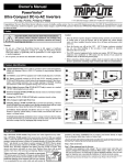
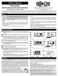
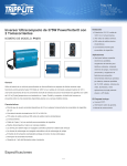
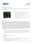
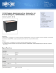
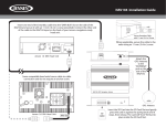
200211057 PV Owner’s Manual Addendum.qxd
1111 W. 35th Street Chicago, IL 60609 USA
Customer Support: (773) 869-1234
www.tripplite.com
11/21/2002
1:57 PM
Page 1
Owner’s Manual
Addendum
PowerVerter Hardwired Electrical Connections
& Dip Switch Settings
®
Power Inverters (120V, 60 Hz)
IMPORTANT SAFETY INSTRUCTIONS. This addendum and the accompanying
manual contain information concerning the proper installation of Tripp Lite
equipment. SAVE THESE INSTRUCTIONS.
Your PowerVerter is identical to the Inverter/Charger described in the accompanying owner’s manual with
the two exceptions (Hardwire Connection and Dip Switch Settings) described here.
Hardwire AC Connection
Warning! Consult a qualified electrician and follow all applicable electrical
codes and requirements for hardwire connection. Disconnect DC input and
AC utility supply before attempting hardwiring.
Connection for Models with Hardwire Terminals
Remove the screws and cover plate over the hardwire terminal box. Remove the knockout covers closest to
the desired electrical source and to your equipment. Attach ½" diameter conduits (user-supplied) to the
knockouts and thread wires through. Connect the conduits to each other with the ground bond connection
supplied.
Ground
• Connect the incoming and outgoing ground
wires to the GROUND (green) terminal. 1
AC Input
• Connect the incoming hot wire to the input hot
(brown) terminal. 2
• Connect the incoming neutral wire to the input
neutral (blue) terminal. 3
“FOR USE WITH COPPER WIRE ONLY”
HOT
2
3
AC Output
1
• Connect the outgoing hot wire to the output
hot (black) terminal. 4
4
• Connect the outgoing neutral wire to the
output neutral (white) terminal. 5
Tighten and affix strain relief. Replace cover plate and tighten screws.
IN
NEUTRAL
5
IN
GROUND
IN
GROUND
OUT
HOT
OUT
NEUTRAL
OUT
200211057 PV Owner’s Manual Addendum.qxd
11/21/2002
1:57 PM
Page 2
Dip Switch Settings
The Dip Switch settings described below replace the Dip Switch settings described in the accompanying
owner’s manual.
INPUT C/B 10A
OUTPUT C/B 12A
Using a small tool, configure your Inverter/Charger by setting the four DIP Switches (located on the front
panel of your unit; see diagram) as follows:
Select Battery Type—REQUIRED
(DIP Switch #1)
CAUTION: The Battery Type DIP Switch setting must match the type of batteries you connect, or your batteries may be degraded or damaged
over an extended period of time.
Battery Type
Switch Position
Gel Cell (Sealed) Battery
Up
Wet Cell (Vented) Battery
Down (factory setting)
Select High AC Input Voltage Point for Switching to Battery—OPTIONAL
(DIP Switch #2)
Voltage
Switch Position
145V
Up
135V
Down (factory setting)
Select Low AC Input Voltage Point for Switching to Battery—OPTIONAL
(DIP Switch #3)
Voltage
Switch Position
105V
Up
95V
Down (factory setting)
Set Battery Charging Amps—OPTIONAL
(DIP Switch #4)
By setting on high charging, your batteries will charge at maximum speed. When setting on low charging,
you lengthen the life of your batteries (especially smaller ones).
Battery Charger
Switch Position
High Charge Amp
Up
Low Charge Amp
Down (factory setting)
High Charge Amp
Low Charge Amp
200211057
93-2105