1
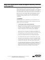
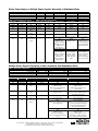
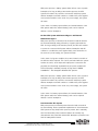
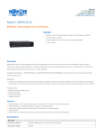
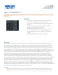
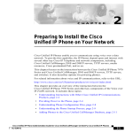
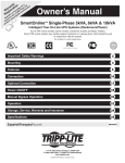
www.tripplite.com
Practical Power Guidelines for VoIP and
Internet Telephony Applications
by David Slotten
Cisco, Cisco Systems, the Cisco Systems logo, and the Cisco Square Bridge logo
are registered trademarks or trademarks of Cisco Systems, Inc. and/or its affiliates
in the U.S. and certain other countries.
WHITE
PAPER
95-2914
Integrate Backup Power into VoIP Networks
Voice over IP (VoIP) is exploding in popularity as an application for business
data networks. VoIP promises to consolidate a company's data and
telecommunications infrastructure as well as its support resources. As a
result, a company can lower its hardware and service costs while raising
productivity through the use of more elaborate and customizable telephony
applications.
Unfortunately, there are serious limitations inherent to the data networks
that are increasingly called upon to support VoIP. The primary limitation is
power availability. Before moving voice traffic from traditional circuitswitched public phone systems to private data network connections, one
must consider a public phone system's unique attribute—battery support. In
order to deliver extremely high availability for such vital services as
emergency 911 support in the event of extended power outages, public
phone systems are connected to massive battery arrays.
While most data networks have some type of backup support during power
outages (provided by UPS Systems and/or generators), the backup runtime
is generally much less than the 4 to 8 hours of backup that is typically
provided for public phone systems. Because of this shortcoming, VoIP
applications generally require an increase in the UPS System-supported
power capacity (e.g. more or larger UPS Systems). Increased UPS System
capacity provides power for network-dependent phones and increases
overall backup runtime to ensure that normal telephone operation (including
911 service) remains available in the event of an extended power outage.
Reflecting on important lessons learned during its own transition to IP
telephony, Cisco provides several best-practice recommendations. One of
the most important recommendations is installing a UPS System to
guarantee availability:
“Plan Your Power: When an IP network carries voice,
reliability is essential. In case of an emergency,
people need to summon assistance by dialing 911.
When using inline power to switches and routers, make
sure they are connected to an uninterruptible power
supply [UPS System] to guarantee dial tone if the
power should go out.”
Source: Cisco Systems white paper “The Transition to IP Telephony at Cisco Systems”.
http://www.cisco.com/en/US/tech/tk652/tk701/technologies_white_paper09186a00800cb7fd.shtml
© 2008 TRIPP LITE. ALL RIGHTS RESERVED. THE POLICY OF TRIPP LITE IS ONE OF CONTINUOUS IMPROVEMENT.
SPECIFICATIONS ARE SUBJECT TO CHANGE WITHOUT NOTICE.
ALL TRADEMARKS ARE THE PROPERTY OF THEIR RESPECTIVE OWNERS.
2
Consider the Diverse Needs of VoIP Network Equipment
Before selecting a UPS System to ensure 100% availability of IP telephony
systems, it's important to consider the unique requirements of VoIP network
equipment. Network designs hosting VoIP applications will vary widely from
business to business due to a number of variables, including the scale of
the network and the variety of legacy equipment involved. However, three
devices are common to all networks:
Client Devices (phones, PC-based soft phones, etc.)
During the transition to IP telephony, these devices will either (a) derive
their power from the network cable via a Power over Ethernet (PoE)
connection scheme, or (b) plug into a local AC source.
Typical VoIP
Network Design
If they plug into a local AC source, they must be protected by a UPS
System. Often a desktop UPS not only safeguards phone service, but also
guarantees file integrity for associated PC users.
Networking Devices (switches, routers, etc.)
During the transition to IP telephony, port capacity on the network and in
wiring closets will increase to accommodate additional devices (phones)
connected to the network. Increased port capacity will increase the power
requirements placed on your UPS System, either reducing runtime or
overloading the UPS. Note that if a networking device also supplies Power
over Ethernet, the aggregate load of all client devices will also be borne by
the networking device's UPS System.
Source: Cisco Systems white paper
“Power and Cooling for VoIP and IP
Telephony Applications”.
http://www.cisco.com/application/pdf/en/
us/guest/netsol/ns412/c654/cdccont_
0900aecd801a2c5f.pdf
Generally, an existing UPS will be inadequate to (a) power the increased
load [watts] and (b) power the load for an acceptable length of time. Five to
fifteen minutes of runtime provided to gracefully shut down the typical data
network is inadequate for IP telephony users who expect phone service to
continue for HOURS, not minutes.
Call Processing Devices (servers and related storage systems)
During the transition to IP telephony, dedicated servers are typically added
to drive voice and messaging applications, while storage systems are
required for voicemail and other messaging applications. Similar to the
increased burden placed on networking devices, call processing devices will
experience increased loads and will require increased runtime.
© 2008 TRIPP LITE. ALL RIGHTS RESERVED. THE POLICY OF TRIPP LITE IS ONE OF CONTINUOUS IMPROVEMENT.
SPECIFICATIONS ARE SUBJECT TO CHANGE WITHOUT NOTICE.
ALL TRADEMARKS ARE THE PROPERTY OF THEIR RESPECTIVE OWNERS.
3
Select a UPS System which Provides the Highest Availability, Resiliency
and Manageability
When selecting a UPS System, the most obvious criterion to consider is
whether a UPS System has enough capacity (VA/watts) to power equipment
while having enough battery capacity to operate during a power outage for
your required duration. Specific Tripp Lite UPS System recommendations are
listed at the end of this document. Often overlooked during the selection
process, however, are more subtle, yet critical, criteria that should be
considered, including availability, resiliency to power anomalies and
manageability.
1. Availability
Availability hinges on three considerations: the VoIP equipment's power
supply configuration, the UPS System's battery configuration and the UPS
System's power electronics topology.
A. VoIP Equipment Power Supply Configuration
Many switches and routers are equipped with redundant power supply
capability. If one power supply fails, a second power supply steps in
and powers the device. Redundant power supply configurations are
strongly recommended to ensure continuous system availability.
Whether one or two power supplies are deployed, the equipment can
draw power from one of three sources: directly from facility power alone
(for simplicity's sake we will use the term “wall” to describe this
source), from a single UPS System or from multiple UPS Systems.
The following tables detail a switch's operational status, from a power
perspective, in both redundant and combined (non-redundant) modes.
The tables detail switch status under a variety of operational scenarios,
including power supply failure, utility failure and UPS System failure.
Note: Larger switches often have the capability to be alternatively configured to operate in
a combined (non-redundant) configuration. In combined mode, two power supplies'
capacities will be summed. A true doubling is not generally achieved. A factor of 1.67x is
typical. In combined mode, there is no redundancy. Should a power supply fail, the
available power is generally reduced to the capacity of a single power supply.
© 2008 TRIPP LITE. ALL RIGHTS RESERVED. THE POLICY OF TRIPP LITE IS ONE OF CONTINUOUS IMPROVEMENT.
SPECIFICATIONS ARE SUBJECT TO CHANGE WITHOUT NOTICE.
ALL TRADEMARKS ARE THE PROPERTY OF THEIR RESPECTIVE OWNERS.
4
Single Power Supply, or Multiple Power Supplies Operating in Redundant Mode
STEP 1: Determine Configuration
Configuration
Power Supply
Power Source
1
PS1
Wall
2
PS1
Wall
3
PS2
Wall
PS1
UPS1
PS2
Wall
4
PS1 & PS2
UPS1
STEP 3: Consider System Status
STEP 2: Consider Failure Scenarios
PS1 Status
Utility Status UPS Status System Status System Status System Status
System Status
OK
OK
OK
OK
OK
OK
OK
Failure
OK
OK
Crash
OK
OK
Crash
OK
Blackout
OK
Crash
Crash
OK
OK
OK
Blackout
UPS1 Battery
Crash
Crash
Crash
Crash
Fails
OK
Blackout
UPS1 Internal
Crash
Crash
Crash
Crash
Fault
OK
OK
UPS1 Battery
—
—
OK
OK
Fails
Hot swap battery
Hot swap battery
Line-Interactive UPS Systems
OK
OK
UPS1 Internal
—
—
OK
Crash
Fault
Replace UPS.
Replace UPS.
System on PS2/Wall.
Vulnerable to outage
during UPS
replacement
On-Line UPS Systems
OK
OK
UPS on bypass,
UPS on bypass.
System on PS2/Wall. System on Wall.
Replace UPS1.
Services down*
Vulnerable to
while replacing
outage during UPS
UPS1
replacement
5
PS1
UPS1
PS2
UPS2
System Status
OK
OK
OK
OK
OK
OK
Hot swap battery
OK
Replace UPS.
System on PS2/UPS2.
Services OK during
UPS replacement
OK
UPS on bypass,
System on PS2/UPS2.
Replace UPS1.
Services OK during
UPS replacement
*SmartOnline Hot-Swappable Modular 5-16KVA UPS system hardware can be hot swapped without service outage.
Multiple Power Supplies Operating in Dual (Combined, Non-Redundant) Mode
STEP 1: Determine Configuration
Configuration
Power Supply
Power Source
STEP 2: Consider Failure Scenarios
PS1 Status
Utility Status UPS Status
OK
OK
OK
Failure
OK
OK
OK
Blackout
OK
OK
Blackout
UPS1 Battery
Fails
1
PS1
Wall
2
PS2
Wall
PS1
3
PS2
UPS1
STEP 3: Consider System Status
System Status
System Status
OK
OK
Reduced Output
OK
Crash
OK
Crash
Crash
Replace UPS1.
Output reduced during UPS
replacement
—
Crash
Replace UPS1
OK
Blackout
UPS1 Internal
Fault
OK
OK
UPS1 Battery
Fails
—
OK
OK
UPS1 Internal
Fault
—
OK
Hot swap battery
Line-Interactive UPS Systems
Crash
Replace UPS. Plug into wall until
UPS replacement
On-Line UPS Systems
OK
Replace UPS1.
Both PS on UPS Bypass.
Services down* while replacing
UPS1
PS1
UPS1
PS2
UPS2
System Status
OK
OK
OK
Reduced Output
Replace UPS1.
Output reduced during UPS
replacement
Reduced Output
Replace UPS1. Output reduced
until UPS1 replacement
OK
Hot swap battery
Reduced Output
Replace UPS1. Plug PS1 into wall
to restore full power until UPS1
replacement. Output reduced
until UPS1 replacement
OK
Replace UPS1.
PS1 on UPS1 Bypass circuit,
vulnerable to outage. Reduced
power during UPS1 replacement
*SmartOnline Hot-Swappable Modular 5-16KVA UPS system hardware can be hot swapped without service outage.
© 2008 TRIPP LITE. ALL RIGHTS RESERVED. THE POLICY OF TRIPP LITE IS ONE OF CONTINUOUS IMPROVEMENT.
SPECIFICATIONS ARE SUBJECT TO CHANGE WITHOUT NOTICE.
ALL TRADEMARKS ARE THE PROPERTY OF THEIR RESPECTIVE OWNERS.
5
B. UPS System Battery Configuration
UPS System availability, and therefore VoIP system availability, is most
critically dependent upon the capacity of the UPS System's battery
configuration. The number of UPS System batteries, both internal and
external, determines the amount of runtime that is provided during a
power outage. As mentioned previously, the runtime must fit the
application. Most existing data networks are unlikely to provide reserve
runtime power comparable to the public switched phone network. One
has to determine a runtime estimate of what is adequate or desirable
specifically for a VoIP application. Most users conclude that hours, not
minutes, of backup runtime are required to maintain voice operations.
Like any estimate, a runtime estimate will be imperfect and will also be
impacted by future capacity requirements (such as the addition of more
phones). Therefore, it is critical that the selected UPS System can
accommodate external battery packs to increase runtime as needs
increase, or maintain runtime in a growing phone environment.
Runtime scalability with external battery packs also yields the ability to
hot swap battery packs at the end of their useful life without a service
interruption. Similar hot swap battery replacement is also the norm for
the UPS System's internal batteries.
C. UPS System Power Electronics
If a UPS System's power electronics fail during a utility power outage,
the supported IP telephony system will obviously crash. If the UPS
System failure occurs while utility power is present, however, different
UPS power electronics topologies can impact IP telephony system
availability in different ways.
On-Line UPS System with Internal Bypass
With power present, an internal power electronics fault in an on-line
UPS System will result in the load automatically being powered by a
bypass path inside the UPS. As long as utility power remains present,
the UPS will continue to power the connected IP telephony system
without interruption and will continue to condition the power against
basic power anomalies. In the event of a power outage, the system
will crash.
Upon development of a bypass condition, a service interruption needs
to be planned to replace the UPS System.
© 2008 TRIPP LITE. ALL RIGHTS RESERVED. THE POLICY OF TRIPP LITE IS ONE OF CONTINUOUS IMPROVEMENT.
SPECIFICATIONS ARE SUBJECT TO CHANGE WITHOUT NOTICE.
ALL TRADEMARKS ARE THE PROPERTY OF THEIR RESPECTIVE OWNERS.
6
With power present, a battery system failure will not cause a system
interruption. As long as utility power remains present, the UPS
System will continue to power the connected IP telephony system
without interruption and will continue to condition the power against
most power anomalies. In the event of a power outage, the system
will crash.
In the event of a battery system failure, the internal batteries of the
UPS System and/or the external battery packs can be replaced
without a service interruption.
On-Line UPS System with Internal Bypass and External
Maintenance Bypass
With power present, an internal power electronics fault will result in
the load automatically being powered by a bypass path inside the
UPS. As long as utility power remains present, the UPS will continue
to power the connected VoIP system without interruption and will
continue to condition the power against basic power anomalies. In
the event of a power outage, the system will crash.
In the event of a bypass condition, the power electronics module of
the UPS should be replaced. This can be performed while the system
remains in service, as the input and output power connections are
physically and electrically separated from the power module itself.
This functionality is available presently in Tripp Lite's 5-16KVA
SmartOnline™ Hot-Swappable Modular UPS Systems.
With power present, a battery system failure will not cause a system
interruption. As long as utility power remains present, the UPS
System will continue to power the connected IP telephony system
without interruption and will continue to condition the power against
most power anomalies. In the event of a power outage, the system
will crash.
In the event of a battery system failure, the internal batteries of the
UPS System and/or the external battery packs can be replaced
without a service interruption.
Line-Interactive UPS System
With power present, an internal power electronics fault can result in
the load crashing. As the operational requirements of a line-interactive
UPS System are very simple when power is present, this is extremely
rare. Line-interactive power electronics failures are normally only
detected when the power fails and the UPS attempts to power the load
from its battery-driven inverter.
© 2008 TRIPP LITE. ALL RIGHTS RESERVED. THE POLICY OF TRIPP LITE IS ONE OF CONTINUOUS IMPROVEMENT.
SPECIFICATIONS ARE SUBJECT TO CHANGE WITHOUT NOTICE.
ALL TRADEMARKS ARE THE PROPERTY OF THEIR RESPECTIVE OWNERS.
7
In the event of a power electronics failure, a service interruption
needs to be planned to replace the UPS System.
With power present, a battery system failure will not cause a system
interruption. As long as utility power remains present, the UPS
System will continue to power the connected IP telephony system
without interruption and will continue to condition the power against
many power anomalies. In the event of a power outage, the system
will crash.
In the event of a battery system failure, the internal batteries of the
UPS System and/or the external battery packs can be replaced
without a service interruption.
2. Resiliency to Power Anomalies
The fundamental outcome one hopes for in adding UPS System support to
a network is to enhance system availability. But an additional concept—
resiliency—is very important as well. UPS System resiliency reflects the
ability to respond positively to a number of operating variables.
A. Voltage Variation
Currently, one of the most popular UPS System topologies for VoIP is
provided by on-line UPS Systems. An on-line UPS System can deliver
perfect power even if it encounters a very wide range of input voltages.
The on-line UPS does this without relying on its battery reserves, leaving it
well prepared to respond to a power outage. Because of its continuous
AC-DC-AC conversion process, during an outage an on-line UPS System
will also exhibit zero transfer time between power failure detection and
power delivery to your equipment. On-line UPS Systems are widely
acknowledged to be compatible with all types of VoIP devices.
In many networks with distributed UPS Systems, line-interactive UPS
Systems are widely deployed. If input voltage levels are below the lineinteractive UPS System's automatic correction capability, the UPS will
switch to battery to maintain acceptable output voltage. In areas with
chronic extreme brownouts, this frequent switching to battery can reduce
reserve power as well as shorten battery service life—putting critical
systems at risk in an outage.
While the transfer time of a line-interactive UPS System (several
milliseconds) is extremely fast, this short delay has been theorized as the
cause of packet losses, or even system shutdown in some applications.
Depending on your power environment and the sensitivity of your IP
telephony components, a line-interactive UPS System may or may not be
© 2008 TRIPP LITE. ALL RIGHTS RESERVED. THE POLICY OF TRIPP LITE IS ONE OF CONTINUOUS IMPROVEMENT.
SPECIFICATIONS ARE SUBJECT TO CHANGE WITHOUT NOTICE.
ALL TRADEMARKS ARE THE PROPERTY OF THEIR RESPECTIVE OWNERS.
8
adequate. Generally, line-interactive UPS Systems do not pose a problem.
This is the subject of some debate and is generally presented as a major
issue by vendors biased towards selling online UPS Systems.
Line-interactive UPS Systems do tend to cost less than on-line UPS
Systems and operate with higher efficiency, reducing electrical costs.
In theory, an on-line UPS System battery should be used less frequently
due to input voltage variation, and will therefore last longer. This advantage
will manifest itself more as the frequency of input voltage variation
increases.
B. Harmonic Distortion
Only an on-line UPS System will address input harmonic distortion.
Because an on-line UPS System deconstructs and reconstructs the input
power, it can deliver distortion-free power. A line-interactive UPS System
will pass through input waveform distortions. Harmonic distortion tends to
be an elusive “gremlin” issue when it affects connected loads.
C. Transient Spikes (or “Surges”)
Both line-interactive and on-line UPS Systems address sudden increases in
voltage.
D. Electromagnetic Interference
While both line-interactive and on-line UPS Systems address these
phenomena, an on-line UPS typically offers far superior filtering capability.
3. Manageability
VoIP system availability is closely tied to UPS System manageability. To
ensure continuous availability, UPS Systems must be incorporated as an
integral part of a sound hardware management scheme. UPS Systems are
extremely manageable and responsive, communicating their status
automatically and triggering application shutdowns prior to battery
exhaustion in the event of a power outage or extreme voltage variation.
There are various methods to communicate with UPS systems, including
SNMP, Web, network software and direct connection. While most users
choose SNMP/Web accessory cards installed inside UPS Systems for
communication, the most essential requirement is to deploy and use some
method of communication. Without a management application running for
your UPS Systems, the day will come when the UPS batteries fail and your
system fails as your power fails. Simple management steps taken at
installation can save significant problems later.
© 2008 TRIPP LITE. ALL RIGHTS RESERVED. THE POLICY OF TRIPP LITE IS ONE OF CONTINUOUS IMPROVEMENT.
SPECIFICATIONS ARE SUBJECT TO CHANGE WITHOUT NOTICE.
ALL TRADEMARKS ARE THE PROPERTY OF THEIR RESPECTIVE OWNERS.
9
Alerts available from most UPS Systems and network cards include:
• Voltage levels
• Current levels
• Temperature levels
• Humidity levels
• Dry contacts for fire, water, security, etc.
• Battery capacity
• Battery failure
Commands from the administrator to most UPS Systems include:
• Reboot system
• Reboot outlet(s)
• Shut down system
• Shut down outlet(s)
• Run inverter/battery test
Tripp Lite presents a uniquely simple management scheme for VoIP
UPS System hardware. Whether management is through an IP-addressed
SNMP/Web accessory card or PowerAlert Software, Tripp Lite provides
administrators with a single JAVA-based user interface. The commonality
within this design approach makes it ideal for managing VoIP applications
of all scales across multiple OS platforms.
During a power failure, Tripp Lite's PowerAlert Software ensures a smooth
and customizable shutdown of call processing and voice messaging
applications as well as the underlying operating system.
As a unique feature, Tripp Lite's PowerAlert Software and network accessory
card (SNMPWEBCARD) are designed to accommodate multiple power
supply and UPS System hardware deployments. With a single IP address
assigned to the SNMPWEBCARD (or a single PC/Server running PowerAlert)
users can manage multiple redundant UPS Systems working in tandem to
provide optimal power to the IP telephony system's single or multiple power
supplies.
Alternative UPS System manufacturers require each UPS to be managed
individually. With these UPS Systems, there is no easy way to manage their
redundant operation without expensive and space-consuming external
power-switching accessories.
© 2008 TRIPP LITE. ALL RIGHTS RESERVED. THE POLICY OF TRIPP LITE IS ONE OF CONTINUOUS IMPROVEMENT.
SPECIFICATIONS ARE SUBJECT TO CHANGE WITHOUT NOTICE.
ALL TRADEMARKS ARE THE PROPERTY OF THEIR RESPECTIVE OWNERS.
10
Tripp Lite's PowerAlert Software, version 12.5—which is part of an
integrated VoIP power solution that includes a Tripp Lite UPS System—has
met the Cisco Technology Developer Partner Program test criteria for
interoperability with Media Convergence Servers running CallManager,
versions 3.3(4) and 4.0(2). Through participation in the Cisco Technology
Developer Partner Program, Tripp Lite's integrated VoIP solution provides
continuous IP telephony availability to enterprise customers.
As an additional management tool, PowerAlert also offers centralized
management within a NMS-style, management tool.
Another unique manageability product provided by Tripp Lite is its Watchdog
Service Monitoring/Rebooting Software. Tripp Lite's Watchdog Software
ensures maximum availability, eliminating call processing server downtime
by automatically rebooting locked-up or poorly performing system service
applications. If a locked service cannot be rebooted, Watchdog Software
will automatically direct PowerAlert Software to reboot the server. If the
server is non-responsive, the UPS System will power down and then restart
the attached devices.
Recommended Tripp Lite UPS Systems for VoIP Applications
Establishing an adequate power protection infrastructure is essential. Again, three
areas of demand must be addressed: Client, Network and Call Processing.
Client Devices (phones, PC-based soft phones, etc.)
• IP Phones
If the phone is powered by Ethernet (PoE), it is switch supported
and no client UPS System is required. (Backup will be provided
at the switch.)
If the phone plugs into the utility wall outlet, a UPS System is required.
– Up to 4 hours - Tripp Lite UPS model: INTERNET750U
• Soft Phones (PC based)
Typically, a UPS System is required:
– Up to 1 hour - Tripp Lite UPS model: OMNIVS1500XL
– Up to 3 hours - Tripp Lite UPS model: OMNIVS1500XL
(Plus Tripp Lite battery pack model: BP24V28-2U
• Soft Phones (Notebook PC based)
– Up to 2 hours - internal notebook battery support
– Up to 4 hours - Tripp Lite UPS model: INTERNET750U
© 2008 TRIPP LITE. ALL RIGHTS RESERVED. THE POLICY OF TRIPP LITE IS ONE OF CONTINUOUS IMPROVEMENT.
SPECIFICATIONS ARE SUBJECT TO CHANGE WITHOUT NOTICE.
ALL TRADEMARKS ARE THE PROPERTY OF THEIR RESPECTIVE OWNERS.
11
Networking Devices (switches, routers, etc.)
Networking hardware will typically drive the most significant changes to your
existing power infrastructure. With requirements spanning buildings and
remote wiring closets, existing facility-wide backup plans are often
impractical or unable to address the requirements of mid-size and large
switches. Focused UPS System additions with extended runtime battery
configurations more efficiently add the high level of availability that VoIP
users demand.
Tripp Lite maintains interactive sizing and configuration resources at
www.tripplite.com/selector. We also welcome your contact with our
technical staff via [email protected] or (773) 869-1234.
Basic sizing is as simple as…
1. Determining the power consumption of your equipment:
Volts x Amps = VA.
2. Ensuring that the UPS System has enough power and outlets to
accommodate your equipment.
Many larger routers and switches accommodate multiple power supplies.
Once you have identified your power supply type and quantity, use the
following details to find a specific UPS System solution for your needs:
1. Identify power supply configuration
a. Single power supply or two supplies operating in redundant mode
b. Dual (combined) mode
2. Determine UPS System protection scheme
a. Single UPS System for both power supplies
b. Single UPS System per power supply (higher availability)
3. Estimate desired runtime during power outage
© 2008 TRIPP LITE. ALL RIGHTS RESERVED. THE POLICY OF TRIPP LITE IS ONE OF CONTINUOUS IMPROVEMENT.
SPECIFICATIONS ARE SUBJECT TO CHANGE WITHOUT NOTICE.
ALL TRADEMARKS ARE THE PROPERTY OF THEIR RESPECTIVE OWNERS.
12
Call Processing Devices (servers and related storage systems)
Typically, additional server and storage resources are added to handle call
processing, voice messaging and other telephony applications. Such
systems tend to reside within the data center and are multi-vendor in origin.
For configuration assistance specific to your rollout, please contact
Tripp Lite. Tripp Lite maintains interactive sizing and configuration resources
at www.tripplite.com/selector. We also welcome your contact with our
technical staff via [email protected] or (773) 869-1234.
Common Tripp Lite UPS Systems Recommended for VoIP Networking
Device Applications (Specifications & Runtime Charts)
UPS System Specifications
Input
Nominal
Voltage
Output
Model
Range
Voltage
SmartOnline On-Line UPS Systems
SU2200RTXL2Ua
65-138
120
(110/120)
SU3000RTXL3U
65-138
120
(110/120)
Capacity
(VA/Watts)
Outlet
Quantity
Outlet
Type
Input Plug
Type
RU
Depth
Bypass
2200/1600
7
5-20P
2U
19 in.
Internal
3000/2400
9
6 (5-20R)
1 (L5-20R)
4 (5-15R)
4 (5-20R)
1 (L5-30R)
6 (6-20R)
2 (L6-20R)
2 (L6-20R)
2 (L6-30R)
12 (5-20R)
2 (L6-20R)
2 (L6-30R)
8 (5-15/20R)
2 (L6-20R)
2 (L6-30R)
Hardwire*
5-20P
3U
26 in.
Internal
L6-20P
3U
21 in.
Internal
L6-30P
7U
21 in.
Internal
L6-30P
5U
21 in.
Internal
L14-30P
4U
30.75 in.
Internal/External
Hardwire*
9U
26 in.
Internal/External
8 (5-15/20R)
2 (L6-20R)
2 (L6-30R)
4 (L6-20R)
2 (L6-30R)
12 (5-15/20R)
4 (L6-20R)
2 (L6-30R)
Hardwire
4 (5-15/20R)
2 (L6-20R)
2 (L6-30R)
4 (L6-20R)
2 (L6-30R)
24 (5-15/20R)
4 (L6-20R)
2 (L6-30R)
Hardwire
L14-30P
4U
30.75 in.
Internal/External
Hardwire
6U
31.5 in.
Internal/External
Hardwire
8U
31.5 in.
Internal/External
Hardwire
4U
34 in.
Internal/External
Hardwire
6U
31.5 in.
Internal/External
Hardwire
10U
31.5 in.
Internal/External
Hardwire
9U
31.5 in.
Internal/External
Hardwire
5 (5-15/20R)
2 (L6-30R)
6 (C19)
Hardwire
8U
40.5 in.
Internal/External
SU3000RTXL3UHV
160-275
208/240
3000/2400
8
SU5000RT3U
156-276
208 & 120
5000/3500
16
SU5000RT3UHV
156-276
208/240
5000/3500
4
SU5000RT4U
65-140
(L-N)
208/240
& 120
5000/3800
12
SU6000RT3U
156-276
6000/4200
Hardwire*
SU6000RT4U
65-140
(L-N)
208/240
& 120
208/240
& 120
6000/4200
12
SU8000RT3U
156-276
208/240
8000/6400
6
SU8000RT3U1TF
156-276
208 & 120
7500/6000
18
SU8000RT4U
65-140
(L-N)
208/240
& 120
8000/5600
8
SU10000RT3U
156-276
208/240
10000/8000
6
SU10000RT3U2TF
156-276
208 & 120
10000/8000
30
SU10KRT3U
156-276
10000/8000
Hardwire
SU16000RT4U
65-140
(L-N)
208/240
& 120
208/240
& 120
16000/11200
+13
* SU6000RT3U can provide outlets when used with optional back panel accessory (SUPDM12) which provides two L6-20R, one L6-30R and ten 5-20R outlets and
a cord with a L6-30P input plug.
© 2008 TRIPP LITE. ALL RIGHTS RESERVED. THE POLICY OF TRIPP LITE IS ONE OF CONTINUOUS IMPROVEMENT.
SPECIFICATIONS ARE SUBJECT TO CHANGE WITHOUT NOTICE.
ALL TRADEMARKS ARE THE PROPERTY OF THEIR RESPECTIVE OWNERS.
13
SmartPro® Line-Interactive UPS Systems
Input
Nominal
Voltage
Output
Model
Range
Voltage
SMART1500CRMXL
83-145
120
SMART2200RMXL2U
120
120
Capacity
(VA/Watts)
1500/1440
2200/1600
Outlet
Quantity
8
8
SMART2200CRMXL
SMART3000RM2U
83-145
120
120
120
2200/1900
3000/2250
8
9
SMART3000CRMXL
83-145
120
3000/2880
9
SMART5000XFMRXL
208
208 & 120
5000/3750
11
UPS System Extended Runtime
SmartOnline On-Line UPS Systems
Half load (Watts)
Runtime (minutes)
Full Load (Watts) with included batteries
Outlet
Type
8 (5-15R)
4 (5-15R)
4 (5-20R)
4 (5-15R)
4 (5-15R)
4 (5-20R)
1 (L5-30R)
8 (5-15R)
1 (L5-30R)
8 (5-20R)
2 (L6-20R)
1 (L6-30R)
Input Plug
Type
5-15P
5-20P
RU
2U
2U
Depth
19 in.
17 in.
Bypass
Internal
None
5-20P
L5-30P
4U
2U
16.75 in.
17 in.
Internal
None
L5-30P
4U
16.75 in.
Internal
L6-30P
3U
23 in.
None
Non-Expandable Battery Pack
1
BP48V24-2U
SU2200RTXL2Ua Extended Runtime
(Non-Expandable)
800
14
56
1600
4.5
23
BP72V15-2U
SU3000RTXL3UHV & SU3000RTXL3U Extended Runtime (Non-Expandable)
1200
17
41
2400
6
17
117
50
78
33
SU5000RT3UHV & SU5000RT3U Extended Runtime
1750
20
3500
8
N/A
N/A
73
31
SU5000RT4U Extended Runtime
1900
14
3800
6
N/A
N/A
97.4
42.5
SU6000RT3U Extended Runtime
2100
37
4200
15
N/A
N/A
79
37
SU6000RT4U Extended Runtime
2100
24
4200
9
N/A
N/A
86.6
36.8
SU8000RT3U Extended Runtime
3200
15
6400
6
N/A
N/A
46
18
SU8000RT3U1TF Extended Runtime
3200
15
6400
6
N/A
N/A
46
18.6
Expandable Battery Pack*
2
3
BP48V60RT-3U
(Expandable)
266
378
122
186
BP72V28RT-3U
(Expandable)
158
252
69
108
BP240V10RT-3U
(Expandable)
161.6
225.8
70
100
4
530
246
327
150
291
131
158.4
221.5
70.7
100.7
BP240V10RT-3U
(Expandable)
131
174
58
79
285.5
131.7
141.4
198.2
61.5
87.8
BP240V10RT-3U
(Expandable)
76
109
32
46
256
115.2
222
104
142
60
76.4
108.7
142
31.6
45.6
60.4
BP192V12-3U
SU8000RT4U Extended Runtime
(Expandable)
2800
12
N/A
47
100
141.1
183.8
5600
5
N/A
19
42.8
61.5
81.1
BP240V10RT-3U
SU10KRT3U, SU10000RT3U, & SU10000RT3U2TF Extended Runtime
(Expandable)
4000
10
N/A
35.1
58.6
83.8
110
8000
4
N/A
13.7
23.5
34.1
45.3
BP192V18-4U
SU16000RT4U Extended Runtime
(Expandable)
5600
12
N/A
42.2
70.2
100
130.9
11200
5
N/A
17.1
29.2
42.2
55.9
* Included batteries are contained either internally within the UPS system or are included as an external module, depending on model. ** Battery packs
which are expandable can be connected together for increased runtime. Call Tripp Lite's Application Specialists at (773) 869-1236 for additional extended
runtime solutions to fit your specific load requirements.
© 2008 TRIPP LITE. ALL RIGHTS RESERVED. THE POLICY OF TRIPP LITE IS ONE OF CONTINUOUS IMPROVEMENT.
SPECIFICATIONS ARE SUBJECT TO CHANGE WITHOUT NOTICE.
ALL TRADEMARKS ARE THE PROPERTY OF THEIR RESPECTIVE OWNERS.
14
SmartPro Line-Interactive UPS Systems
Half load (Watts)
Runtime (minutes)
Full Load (Watts) with included batteries
Non-Expandable Battery Pack
1
SMART3000CRMXL Extended Runtime
1440
19
2880
7.5
BP48V24-2U
(Non-Expandable)
70.6
28.1
BP48V24-2U
(Non-Expandable)
62
24.5
BP48V24-2U
(Non-Expandable)
68.8
27.7
BP48V24-2U
(Non-Expandable)
59.9
24.9
BP48V24-2U
(Non-Expandable)
35.4
14.7
SMART5000XFMRXL Extended Runtime
1875
27
3750
10
N/A
N/A
SMART1500CRMXL Extended Runtime
720
28.5
1440
11
SMART2200RMXL2U Extended Runtime
800
16
1540
6
SMART2200CRMXL Extended Runtime
950
28.5
1900
11
SMART3000RM2U Extended Runtime
1120
21.2
1600
8.5
195.5
82.1
128
52.6
154
64.5
124.3
53.4
81.7
35.2
63
24.4
Expandable Battery Pack*
2
3
BP48V48RT4U
(Expandable)
349.2
504.2
152
225
BP48V60RT-3U
(Expandable)
264.3
403.4
113
177.3
BP48V48RT4U
(Expandable)
265.4
378.7
114.8
167.7
BP48V60RT-3U
(Expandable)
256.2
391.5
114.5
179.7
BP48V48RT4U
(Expandable)
144.3
209.5
63.8
94.5
BP48V60RT-3U
(Expandable)
117.9
175.8
47
71.7
4
658.8
299.3
542.9
243.5
492.5
222
527.2
246.6
276
126.4
235.2
97.6
* Battery packs which are "expandable" can be connected together for increased runtime. Call Tripp Lite's Application Specialists at (773) 869-1236 for additional extended runtime solutions to
fit your specific load requirements.
About the author: David Slotten is Director of Product Management
at Tripp Lite. Mr. Slotten joined Tripp Lite in 1990 and has extensive
experience in the sale, marketing, engineering and development of power
protection systems. Mr. Slotten has an MBA from Lake Forest Graduate
School of Management and a bachelor’s degree from the University of
Wisconsin.
For Additional VoIP and Internet Telephony
Application Assistance Call Tripp Lite's
Application Specialists at (773) 869-1236
Tripp Lite World Headquarters • 1111 W. 35th Street • Chicago, IL 60609 USA
(773) 869-1234 • www.tripplite.com
Tripp Lite's PowerAlert Software, version 12.5, has tested compatible with Cisco CallManager, versions 4.0 and 4.1, Cisco 7600 Series Routers, 7500 Series Routers and Catalyst 65XX Layer 3 Switch. Tripp Lite
PowerAlert Software, version 12, has tested compatible with Cisco CallManager, versions 3.3(4)-MCS and 4.0(2)-MCS. The Cisco Compatible logo signifies that Tripp Lite's product has undergone interoperability
testing by Tripp Lite together with Cisco and a third-party test house based on testing criteria set by Cisco. Tripp Lite is solely responsible for the support and warranty of its product. Cisco makes no warranties,
express or implied, with respect to Tripp Lite's product or its inter-operation with the listed Cisco product(s) and disclaims any implied warranties of merchantability, fitness for a particular use or against infringement.
Tripp Lite is a Cisco Technology Developer Partner in the Cisco Technology Developer Program.
Cisco, Cisco Systems, the Cisco Systems logo, and the Cisco Square Bridge logo are registered trademarks or trademarks of Cisco Systems, Inc. and/or its affiliates in the U.S. and certain other countries.
© 2008 TRIPP LITE. ALL RIGHTS RESERVED. THE POLICY OF TRIPP LITE IS ONE OF CONTINUOUS IMPROVEMENT.
SPECIFICATIONS ARE SUBJECT TO CHANGE WITHOUT NOTICE.
ALL TRADEMARKS ARE THE PROPERTY OF THEIR RESPECTIVE OWNERS.
15
200801210 95-2914