1
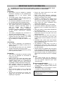
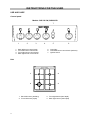
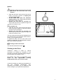
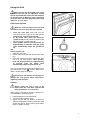
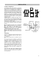
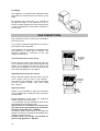
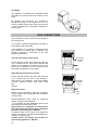
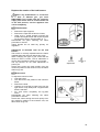
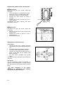
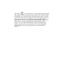
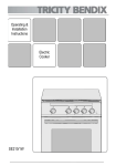
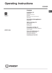
OPERATING & INSTALLATION
INSTRUCTIONS
GAS COOKER
SIG 233/1
GB
CONTENTS
Instructions for the User
Instructions for the Installer
Warnings
4
Technical Features
18
Use and care
5
Use of the appliance
Using the Oven
Using the Grill
Using the Hob
6
6
8
9
Advice for safety
Gas connection
Electrical connections
19
19
20
Installation
21
Gas connection
22
Hints and tips
12
Conversion of gas
24
Maintenance and cleaning
13
Oven bulb replacement
14
Something Not Working
15
Service and spare parts
16
Guarantee Conditions
17
How to read the instruction book?
The symbols below will guide you when reading
the instruction book
Safety instructions
Description of operations step by step
Advice and recommendation
Information environment protection
2
IMPORTANT SAFETY INFORMATION
You MUST read these warnings carefully before installing or using the appliance. If you
need assistance, contact our Customer Care Department on 08705 950950.
Installation
• This cooker must be installed by qualified
personnel, according to the manufacturer’s
instructions and to the relevant British
Standards.
• This cooker is heavy. Take care when moving it.
• Any gas installation must be carried out by a
registered CORGI installer.
• Any electrical installation must be carried out
by a qualified electrician/competent person.
• Remove all packaging before using the cooker.
• This cooker must not be connected to a
combustion products evacuation device. It
shall be installed and connected in
accordance
with
current
installation
regulations. Particular attention shall be given
to the relevant requirements regarding
ventilation.
• This cooker is designed to be connected to a
230-240V, 50Hz electrical supply.
• Ensure that the gas and electrical supply
complies with the type stated on the rating
plate, located near the gas supply pipe.
• Do not attempt to modify the cooker in any
way.
Child Safety
• This cooker is designed to be operated by
adults. Do not allow children to play near or
with the cooker.
• The cooker gets hot when it is in use. Children
should be kept away until it has cooled.
• Children can also injure themselves by pulling
pans or pots off the cooker.
During Use
• This cooker is intended for domestic cooking
only. It is not designed for commercial or
industrial purposes.
• When in use a gas cooker will produce heat
and moisture in the room in which it has been
installed. Ensure there is a continuous air
supply, by keeping air vents in good condition
or installing a cooker hood with a venting hose.
• When using the cooker for a long period time,
the ventilation should be improved, by
opening a window or increasing the extractor
speed.
• Do not use this cooker if it is in contact with
water. Do not operate the cooker with wet
hands.
• The grill pan will become hot during use,
always use oven gloves when removing or
replacing a hot grill pan.
• Ensure the control knobs are in the ‘OFF’
position when not in use.
• When using other electrical appliances,
ensure the cable does not come into contact
with the hot surfaces of the cooker.
• Unstable or misshapen pans should not be
used on the hob burners as unstable pans
can cause an accident by tipping or spillage.
• Never leave the cooker unattended when
cooking with oil and fat.
• Never pull the appliance by the oven handle.
• This cooker should be kept clean at all times.
A build-up of fat or foodstuff could result in a
fire.
• Never use steam or high pressure appliances
for cleaning the oven.
• Never use plastic dishes in the oven or on the
hob burners. Never line any part of the oven
with aluminium foil.
• Always ensure that the oven vent, which is
located at the centre back of the hob, is left
unobstructed to ensure ventilation of the oven
cavity.
• Perishable food, plastic items and aerosols
may be affected by heat and should not be
stored above the cooker.
• The appliance is fitted with a lid: this is
designed as a dust cover when closed, and
as a splash back when open. Do not use for
any other purpose.
• Always remove any spillage from the surface
of the lid before opening, and the appliance
should be allowed to cool before closing the lid.
• After using the cooker, the lid MUST NOT be
closed until the hob and oven are completely
cold.
Service
•
This cooker should only be repaired or
serviced by an authorised Service Engineer
and only genuine approved spare parts
should be used.
Environmental Information
•
•
After installation, please dispose of the
packaging with due regard to safety and the
environment.
When disposing of an old appliance, make it
unusable, by cutting off the cable.
Keep this instruction book for future
reference and ensure it is passed on to
any new owner.
3
INSTRUCTIONS FOR THE USER
USE AND CARE
Control panel
Models: SIG 233/1W, SIG233/1B
7
1
1.
2.
3.
4.
2
3
Back left burner control knob
Front left burner control knob
Front right burner control knob
Back right burner control knob
4
5
6
5. Oven light
6. Oven/Grill burner control knob (selector)
7. Ignition switch
Hob
1
4
2
3
1. Back left burner (auxiliary)
2. Front left burner (rapid)
4
3. Front right burner (semi-rapid)
4. Back right burner (semi-rapid)
USE OF APPLIANCE
Before the First Use of the Cooker
Remove all packaging both inside and
outside of the cooker, before using it.
Before first use, the oven should be heated
without food. During this time, an unpleasant
odour may be emitted. This is quite normal.
1. Remove the oven accessories and ensure all
packaging has been removed.
2. Ignite the oven burner (see instructions) and
turn the control knob to maximum.
3. Open a window for ventilation.
4. Allow the oven to run empty for
approximately 45 minutes.
This procedure should be repeated with the grill
function for approximately 5-10 minutes.
Using the Oven
The cooker gets hot when it is in use.
Children should be kept away until it has
cooled.
Stand clear when opening the drop down
oven door. Do not allow it to fall open support the door using the door handle,
until it is fully open.
When using the oven the lid must be
open to avoid over-heating.
Attention: when turning on the oven and
grill burner the oven door has to be
opened.
4
3
2
The oven has four shelf levels, and is supplied
with one shelf.
The shelf positions are counted from the bottom
of the oven as shown in the diagram.
1
Oven Safety device
The cooker features a thermocouple; if for
any reason the flame should extinguish, the
device will stop the gas flow.
Use
The oven can be used for traditional cooking, or
for grilling, but not both functions simultaneously.
The symbol on the knob corresponds to the
symbol on the control panel.
“8”
“1”
Off
Maximum
Minimum
Grill function
5
Ignition
Attention: when turning on the oven and
grill burner the oven door has to be
opened.
• Open the oven door, push and turn the control
knob to the left to position 8, keeping the
control knob pressed.
• At the same time, push the electronic
ignition knob (see fig). Keep it pushed until the
gas ignites (1 spark / second).
• Release the knob after 10 seconds and
check that the burner is ignited through the
holes in the burner cover.
OR
During a power cut
• Open the oven door, push and turn the control
knob to the left to position 8, and hold a flame
near the hole in the bottom;
• Release the knob after 10 seconds and
check that the burner is ignited through the
holes in the burner cover.
If for any reason the flame should extinguish turn
the control knob to the off position, after at least 1
minute, try to re-ignite the oven.
To adjust the flame, turn the oven knob to the
position corresponding to the temperature desired,
after a few minutes of operation.
Turning off the oven burner
Turn the knob clockwise to mark «
».
Cooking in the Oven
Traditional cooking is made by natural
convection; the heated air circulates on the
principle of ascending and descending draughts.
It is necessary to pre-heat the oven.
All cookers vary and it is important to be
aware
of
the
approximate
cooking
temperatures before you use the cooker.
It may be necessary to adjust the temperature to
suit
your
individual
requirements.
Only
experience will enable you to determine the
correct setting for your personal requirements.
7
Using the Grill
When grilling, the accessible parts of the
appliance are hot and the appliance should
not be left unattended. Take care that children
do not play near it. While the grill is operating
leave the oven door half open and put the grill
deflector “A” into place.
A
Grill burner ignition
Attention: when turning on the oven and
grill burner the oven door has to be opened.
•
•
•
Open the oven door push and turn the
control knob to the right to the “grill symbol”
and keep the control knob pressed.
At the same time, push the electronic
ignition knob (see fig). Keep it pushed until
the gas ignites (1 spark / second).
Upon ignition, keep the knob pressed for
approximately 10 seconds (until the safety
valve automatically keeps the grill burner
lit).
OR
During a power cut
• Open the oven door.
• Hold a flame to the gas grill burner holes (see
fig.).
• Press the oven/grill function control knob, then
turn it to the “grill symbol”. Upon ignition,
keep the knob pressed for approximately
10 seconds (until the safety valve
automatically keeps the grill burner lit).
If for any reason the flame should extinguish turn
the control knob to the " " position, leave for at
least 1 minute and then re-ignite.
The grill pan will become hot during use,
always use oven gloves when removing or
replacing a hot grill pan.
Grilling
When using the grill it has to be
supervised, the oven door opened and
the grill deflector “A” in its place.
When grilling, only the top burner is heating. It is
not necessary to preheat the grill.
• Insert the grill pan on the fourth level.
• Turn the knob to position “grill”.
• Adjust the grid and pan position to allow for
different thicknesses of food. Position the food
closes the grill for faster cooking and further
away for gentler cooking.
7
Grilling meat
When using the grill it has to be
supervised, the oven door opened and
the grill deflector “A” in its place.
• Prepare the meat to be grilled, lightly brush it
with oil on both sides.
• Place it on the roasting grid.
• Turn the oven/grill control knob to position “grill”.
• Slide the roasting grid in the guide 4 and the
roasting tray in the guide 3.
• When the first side is brown, turn the meat
without pricking it in order that the juices are
not lost.
• Grill the second side.
Cooking time is determined by the thickness of
the piece to be grilled not by its weight.
4
3
2
1
Browning
• Turn the oven/grill control knob to the “grill”
position.
• Place the dish on the grid and slide it on shelf
guide 4.
• Leave the dish under the grill for a few
minutes.
Oven light
The oven is equipped with a lamp. It starts
operating when the
panel is pressed .
switch on the control
9
COOKING CHART
Food
Tray type or
dimension
(dxwxh) cm
Material of
the tray
No.
of
tray
Preheating
Shelf
Thermoposition
stat
pos.
Cooking
Time
(min)
Thermostat
pos.
Time
(min)
Roasting meal
- beef
- lamb
Roasting tray
delivered with
the cooker
Enamelled
- pork and veal
1
3
5
20
5
1
3
5
20
5
1
3
5
20
5
3
3
3
3
5
4
4
5
20
20
20
20
5
5
5
5
20 min. for each 0.5 Kg / rare
25 min. for each 0.5 Kg/ medium
30min. for each 0.5 Kg/well done
25 min. for each 0.5 Kg/ medium
30min. for each 0.5 Kg/well done
30 min. for each 0.5 Kg/ medium
35min. for each 0.5 Kg/well done
Poultry
- chicken
- turkey below 4.5 Kg
- turkey over 4.5 Kg
- duck
25-30 min. for each 0.5 Kg
25 min. for each 0.5 Kg
25 min. for each 0.5 Kg
25 min. for each 0.5 Kg
Roasting tray
delivered with
the cooker
Enamelled
1
1
1
1
33x28x0.6
Aluminum
2
2 and 4*
8
20
8
15-20
33x28x0.6
Aluminum
1
3***
8
20
8
15-20
Cakes
- scones
- fettles sponge cake
- rich fruit cake
- small cake
- Victoria sandwich
- apple pie
Ø 26x5
Aluminized
1
3***
4
15
4
30-40
Ø 23x7.6
Tinned steel
1
3***
1
15
1
120-140
33x28x0.6
Aluminum
2
2 and 4*
4
15
4
30-40
33x28x0.6
Aluminum
1
3***
4
15
4
30-40
Ø 20.5x3.5
Aluminized
2
2 and 4*
5
15
5
20-30
Ø 20.5x3.5
Aluminized
1
3***
5
15
5
20-25
Ø 20x5
Aluminized
2
3**
5-6
15
5-6
70-90
Ø 20x5
Aluminized
1
3***
5
15
5
70-90
- bread 1.35 Kg
19.5x9.3x5.5
Tinned steel
3
3
7
20
7
35-45
- bread 0.45 Kg
19.5x9.3x5.5
Tinned steel
1
1***
7
20
7
30-40
Yeast mixture
NOTE: d = deepness; w = width; h = height
Remarks: The recommended cooking conditions give the best results.
* if you should cooking more than one tray, you can take the top tray out of the oven when the cakes are finished and move
the lower tray to the higher shelf to finish the cooking (about 5 min.)
** these two pans are positioned on the same shelf, at the diagonal of the oven grid
*** put the dishes in the center of the shelf
The dishes indicated for cakes and yeast mixture you can find in the shops.
9
Using the Hob
The Hob Burners
The symbol on the control panel shows which
burner is operated by the knob. (See control
panel).
Off
Maximum level
Minimum level
Use the maximum level for boiling and the
minimum for simmering.
Always choose positions between the minimum
and maximum, never between maximum and off.
Ignition of the burners
• Push the knob and turn it left to the “large flame“
symbol.
• At the same time, push the electronic ignition
knob (see fig). Keep it pushed until the gas
ignites (1 spark / second).
• Release the knob and check that the burner
has ignited.
• Upon ignition, adjust the flame as required.
OR
Power Cut
• Push the corresponding knob in completely
and turn it left to the “large flame“ symbol and
ignite with a match.
• Release the knob and check that the burner
has ignited.
• Upon ignition, adjust the flame as required.
If for any reason the flame should extinguish turn
off the relevant control knob, leave for at least
one minute and then re-ignite.
If after a few attempts the burner does not ignite,
check that the burner ring and its cap are
correctly positioned.
Turning off the burners
Turn the control knob clockwise to mark «
».
Do not put anything on the hob that is
liable to melt.
Good use
Selecting the Correct burner
Above every knob there is a symbol for the
corresponding burner.
For good cooking results, always choose pans,
which correctly fit to the diameter of the burner
used (see figs). Choose thick, flat bottom pots.
We recommend the flame is lowered as soon as
the liquid starts boiling.
For a correct ignition always keep the burner ring
and the spark plugs clean.
10
Bad use
(Power waste)
The following diameter pans can be used:
Burner
Rapid
Semi-Rapid
Auxiliary
Power
(kW)
3,00
2,00
1,00
Diameter (mm)
min.
max.
160
280
140
240
120
180
Accessories delivered with the
appliance
The following accessories are supplied with your
appliance.
• Grill Deflector
To be used when the grill is operation.
• Shelf for placing dishes on (roast, pastry
mounds)
The dish should be put in the middle of the
shelf to balance the weight.
• A roasting tray with roasting grid on it.
It is used to collect juice when cooking in it,
place it on the shelf 2.
If you do not use the roasting tray, remove it
from the oven.
• Removable handles
In addition to the accessories supplied we
recommend you only use heatproof dishes/pans
(according to the manufacturer’s instructions).
Removable drawer
The removable drawer is located underneath the
oven cavity.
During cooking the drawer may
become hot if the oven is in use for a long
period of time. Flammable materials such as
oven gloves, tea towels, plastic aprons etc.
should not be stored in the drawer.
Oven accessories such as baking sheets, will
also become hot, therefore care should be taken
when removing these items from the drawer
whilst the oven is in use or still hot.
To open
• Grasp the drawer from underneath and pull it
out as shown.
• To remove the drawer, pull it out to the stop,
then lift it up slowly and pull it out completely.
To replace the drawer follow the same
procedure in reverse.
11
Hints and Tips
Condensation and steam
When food is heated it produces steam in the
same way as a boiling kettle. The oven vents
allow some of this steam to escape. However,
always stand back from the oven when
opening the oven door to allow any build up of
steam or heat to release.
If the steam comes into contact with a cool
surface on the outside of the oven, e.g. a trim, it
will condense and produce water droplets. This
is quite normal and is not a fault with the oven.
To prevent discolouration, regularly wipe away
condensation and also soilage from surfaces.
Cookware
Use any ovenproof cookware,
withstand temperatures of 250°C.
which
will
• The thickness, the material and the colour of
the pan will influence the cooking results.
• When cooking, certain dishes increase in
volume, ensure the pan is large enough.
• To prevent fat dripping when roasting use tall
rim pans proportional to the item being
roasted.
• Prick the skin of poultry and sausages with a
fork before cooking to avoid spitting.
• Use heatproof glass dishes for soufflés.
The effects of dishes on cooking results
Dishes and tins vary in their thickness,
conductivity, colour, etc. which affects the way
they transmit heat to the food inside them.
Oven dishes, etc. should not be placed
directly on the oven base.
A Aluminium, earthenware, oven glassware
and bright shiny utensils reduce cooking and
base browning.
Oven Cooking
• Turn off the oven 5 minutes before the end of
cooking time, and use residual heat to
complete the cooking.
B Enamelled cast iron, anodised aluminium,
aluminium with non-stick interior and coloured
exterior and dark, heavy utensils increase
cooking and base browning.
12
MAINTENANCE AND CLEANING
The oven should be kept clean at all
times. A build-up of fats or other
foodstuffs could result in a fire.
Before cleaning, ensure all control
knobs are in the OFF position, and the
appliance has cooled completely.
Before any maintenance or cleaning
can be carried out, you must
DISCONNECT the cooker from the
electricity supply.
Hob
After every use wipe with a soft cloth well wrung
out in warm water to which a little washing up
liquid has been added, avoiding any leakage
through the holes of the hob. Rinse and dry with a
soft cloth.
To remove more stubborn stains, wet and leave to
dissolve, do not scratch and avoid the use of
abrasive or caustic products that could damage
the enamel.
Cleaning materials
Before using any cleaning materials on your
oven, check that they are suitable and that their
use is recommended by the manufacturer.
Burners
The burner caps and crowns can be removed for
cleaning. Wash the burners caps and crowns using
hot soapy water, and remove marks with a mild
paste cleaner. A well-moistened soap impregnated
steel wool pad can be used with caution, if the
marks are particularly difficult to remove.
After cleaning, be sure to wipe dry with a soft
cloth.
Cleaners that contain bleach should NOT
be used as they may dull the surface
finishes. A steam cleaner is not to be
used. Harsh abrasives should also be
avoided.
External cleaning
We recommend for cleaning cleaners that do
not scratch the surface; Avoid use of metal
objects, steel wool or nylon pads, abrasive or
caustic products, or diluents. Regularly wipe over
the control panel, the cover, oven door and door
seal using a soft cloth well wrung out in warm
water to which a little washing up liquid has been
added.
•
•
•
•
•
•
To prevent damaging or weakening the
door glass panels avoid the use of the
following:
Household detergent and bleaches
Impregnated pads unsuitable for non
stick saucepans
Brillo/Ajax pads or steel wool pads
Chemical oven pads or aerosols
Rust removers
Bath/Sink stain removers
Oven Cavity
The enamelled oven cavity is best cleaned whilst
the oven is still warm.
Wipe the oven over with a soft cloth soaked in
warm soapy water after each use. From time to
time it will be necessary to do a more thorough
cleaning, using a proprietary oven cleaner.
14
DO NOT clean the oven door while the
glass panels are warm. If this precaution is
not observed the glass panel may shatter. If
the door glass panel becomes chipped or has
deep scratches, the glass will be weakened
and must be replaced to prevent the
possibility of the panel shattering.
Contact your local Service Centre who will be
pleased to advise further.
OVEN BULB REPLACEMENT
Ensure that the appliance is switched off
and disconnected from the electricity supply
before replacing the bulb to avoid possibility
of an electric shock.
If the oven bulb needs replacing, it must comply
with the following specifications:
Wattage:
Voltage:
Temperatures:
Thread Type:
25W
230/240V(50Hz)
300ºC
E14
To replace the faulty bulb.
1. Turn the glass cover anticlockwise and
remove.
2. Remove the faulty bulb by turning it anticlockwise and replace with a new one.
3. Refit the glass cover.
Reconnect the appliance to the electricity supply.
14
SOMETHING NOT WORKING
If the appliance is not working correctly, please carry out the following checks, before contacting your
local Service Force Centre.
IMPORTANT: If you call out an engineer to a fault listed below, or to repair a fault caused by
incorrect use or installation, a charge will be made even if the appliance is under guarantee.
Symptoms
Solutions
1. No burner ignition
Check that:
• Gas supply is completely open
• The position of gas pipe is correct
• The burner is not wet
• The burner cap and ring burner have been
replaced correctly after cleaning
2. The gas ring burns unevenly
Check that:
• The main jet is not blocked and the ring
burner is clean of food particles
• The burner cap and ring burner have been
replaced correctly after cleaning
3. One of the oven or grill burners does not Check that:
ignite
• The burner is in its correct place
• The burner is not wet
• The control knob has been pressed for 10
seconds upon ignition
4. Cooking results are not satisfactory
5. Cooking time is too long
6.The oven smokes
Check that:
• The correct temperature has been selected
• The cooking time is adapted
• The grill is placed correctly in the oven
Check that:
• The temperature is correct for the type of
food to be cooked.
Check that:
• The oven does not need cleaning
• The food does not spill over
• There is no excessive fat / juice on the oven
sides
• Check the fuses.
If after these checks, the appliance still does not operate correctly, contact your local Service Force
Centre. When you contact the Service Force Centre you will need to give the following details:
1.
2.
3.
4.
5.
Your name, address and post code.
Your telephone number
Clear and concise details of the fault
The model and serial number of the appliance (found on the rating plate*)
The purchase date
* The rating plate can be found on the lower left hand corner of the front frame of the cavity.
Please note that a valid purchase receipt or guarantee documentation is required for inguarantee service calls.
15
SERVICE AND SPARE PARTS
In the event of your appliance requiring service, or if you wish to purchase spare parts, please contact
your local Service Force Centre by telephoning: -
08705 929929
Your telephone call will be automatically routed to the Service Force Centre covering your post code
area.
For the address of your local Service Force Centre and further information about Service Force,
please visit the website at www.serviceforce.co.uk
In-guarantee customers should ensure that the checks under the heading “Something Not
Working” have been made as the engineer will make a charge if the fault is not a mechanical or
electrical breakdown. Please note that it will be necessary to provide proof of purchase for any
in-guarantee service calls.
CUSTOMER CARE
For general enquiries concerning your Tricity Bendix appliance and or for further information on our
products, contact our Customer Care Department by letter or telephone as follows:
Major Appliances - Customer Care Department
Tricity Bendix
Addington Way
Luton
Bedfordshire
LU4 9QQ
Tel: 08705 950950 (*)
(*) calls to this number may be recorded for training purposes.
16
GUARANTEE CONDITIONS
Standard Guarantee Conditions
We Tricity Bendix undertake that if, within 12 months of the date of the purchase, this Tricity Bendix
appliance or any part thereof is proved to be defective by any reason only of faulty workmanship or
materials, we will, at our option, repair or replace the same FREE OF ANY CHARGE for labour,
materials or carriage on condition that:
• The appliance has been correctly installed and used only on the electricity supply stated on the
rating plate.
• The appliance has been used for normal domestic purposes only, and in accordance with the
manufacturer's instructions.
• The appliance has not been serviced maintained, repaired, taken apart or tampered with by any
person not authorised by us.
• All service work under this guarantee must be undertaken by a Tricity Bendix Service Force
Centre.
• Any appliance or defective part replaced shall become the Company's property.
• This guarantee is in addition to your statutory and other legal rights.
Home visits are made between 8.30am and 5.30pm Monday to Friday. Visits may be available
outside these hours, in which case a premium will be charged.
Exclusions
This guarantee does not cover:
• Damage or calls resulting from transportation, improper use or neglect, the replacement of any light
bulbs or removable parts of glass or plastic.
• Costs incurred for calls to put right an appliance, which is improperly installed, or calls to appliance
outside the United Kingdom.
• Appliances found to be in use within a commercial or similar environment, plus those, which are
the subject to rental agreements.
Products of Tricity Bendix manufacture which are not marketed by Tricity Bendix.
European Guarantee
If you should move to another country within Europe then your guarantee moves with you to your new
home subject to the following qualifications:
• The guarantee starts from the date you first purchased your product.
• The guarantee is for the same period and to the same extent for labour and parts as exist in the
new country of use for this brand or range of products.
• This guarantee relates to you and cannot be transferred to another user.
• Your new home is within the European Community (EC) or European Free Trade Area.
• The product is installed and used in accordance with our instructions and is only used
domestically, i.e. a normal household
• The electrical supply complies with the specification given in the rating label.
• The product is installed taking into account regulations in your new country.
Before you move, please contact your nearest Customer Care Centre, listed below, to give them
details of your new home. They will then ensure that the local Service Organisation is aware of your
move and able to look after you and your appliances.
France
Germany
Italy
Sweden
UK
Senlis
Nürnberg
Pordenone
Stockholm
Luton
+33 (0) 3 44 62 20 13
+49 (0) 800 234 7378
+39 (0) 800117511
+46 (0) 20 78 77 50
+44 (0) 8705 950950
17
INSTRUCTIONS FOR THE INSTALLER
TECHNICAL FEATURES
Free standing
Hob
Class 1
Lid
Pan support
Front right burner
Back right burner
Front left burner
Back left burner
Hob ignition
Oven
Oven
Oven burner power
Grill
Grill burner power
Oven lamp
Oven ignition
Cleaning
Cavity dimensions
Height
Width
Depth
Oven volume
Accessories
Oven shelf
Roasting tray + 2 handles
Roasting grid
Grill deflector
Dimensions
Height
Width
Depth
This appliance complies with the following EEC
Directives :
93/68 ; 73/23 (Low Voltage Directive) and subsequent
modifications,
89/336, 90/31, 93/68 (Electro- magnetical Compatibility
Directive) and subsequent modifications,
90/396 (Gas Appliance Directive) 93/68 (General
Directives) and subsequent modifications.
18
Painted
Enamelled
Semirapid
Semirapid
Rapid
Auxiliary
2000 W
2000 W
3000 W
1000 W
Spark
Gas
3000 W
Gas
2000 W
Lamp 25W type E14
Spark
Manual
267 mm
405 mm
381 mm
41,2 l
900 mm
500 mm
600 mm
ADVICE FOR SAFETY
Gas connections
• Before installation ensure that the local
distribution conditions (gas type and
pressure) and the pre-setting of the
appliance are consistent.
• This appliance must be installed only in a
room with good ventilation.
• This appliance must not connected to a
chimney. It has to be installed and connected
in accordance with the rules in force. Special
attention should be paid to the applicable
disposal concerning ventilation.
• The adjacent furniture panels have to be heat
proof or protected by such material.
• The adjusting conditions of this appliance are
mentioned on the rating plate.
Connection to gas supply.
Check that the gas flow and the diameter of the
supply pipe is sufficient to supply all the
appliances of the installation.
• Check that all connections are tight.
• Install an accessible and visible gas tap to
isolate the appliance.
The
manufacturer
declines
any
responsibility for possible damages resulting
from an installation, which doesn't comply
with current legislation.
-
-
-
-
-
-
20
Installation of flues and ventilation for
gas appliances of rated input not
exceeding 60 kW (1st, 2nd and 3rd family
gases) – Part 2 Specification for
installation of ventilation for gas
appliances – BS 5440 Current editions;
Gas burning appliances – Part 3
Domestic cooking appliances burning
gas – BS 5386 Current editions;
Specification for installation of low
pressure gas pipe work of up to 20mm
nd
family
(R1) in domestic premises (2
gas) – BS 6891 Current editions;
Pipe threads for tubes and fittings where
pressure-tight joints are made on the
threads (metric dimensions) – BS 21
Current editions;
Flexible hoses, end fittings and sockets
for gas burning appliances – BS 669
Current editions;
Installation of domestic gas cooking
st
nd
rd
appliances (1 , 2 and 3 family gases) –
BS 6172: 1990 Current editions;
Electrical connections
Any electrical work required to install
this cooker should be carried out by a
qualified electrician or competent person, in
accordance with the current regulations.
A cut off plug inserted into a 13-amp
socket is a serious safety (shock) hazard.
Ensure that the cut off plug is disposed of
safety.
THIS COOKER MUST BE EARTHED.
The manufacturer declines any liability
should these safety measures not be
observed.
This cooker is designed to be connected to a
230-240V AC 50Hz electrical supply.
Before switching on, make sure the electricity
supply voltage is the same as that indicated on
the cooker rating plate. The rating plate is located
on the oven frame.
Before connecting check that:
The cooker is supplied with a 3-core flexible
supply cord incorporating a 13amp plug fitted. In
the event of having to change the fuse, a 13amp
ASTA approved (BS 1362) fuse must be used.
Should the plug need to be replaced for any
reason, the wires in the mains lead are coloured
in accordance with the following code:
Green and Yellow
Blue
Brown
-
-
- Earth
- Neutral
- Live
Connect the green and yellow (earth) wire to
the terminal in the plug, which is marked with
or
the letter 'E' or the earth symbol
coloured green and yellow.
Connect the blue (neutral) wire to the
terminal in the plug, which is marked with the
letter 'N' or coloured black.
Connect the brown (live) wire to the terminal
in the plug, which is marked with the letter 'L'
or coloured red.
NOTE: The earth wire should be about 2 cm
longer than the live and neutral wires.
Upon completion there must be no cut, or stray
strands of wire present and the cord clamp must
be secure over the outer sheath.
20
• The plug used for connection is easily
accessible when the appliance is installed.
Permanent Connection
In the case of a permanent connection, it is
necessary that you install a double pole switch
between the cooker and the electricity supply
(mains), with a minimum gap of 3mm, between
the switch contacts and of a type suitable for the
required load in compliance with the current
electric regulations.
The switch must not break the yellow and green
earth cable at any point.
Ensure that the cooker supply cord does
not come into contact with surfaces with
temperatures higher than 50 deg. C.
INSTALLATION
Location of appliance
The appliance must be set on a heatproof
floor. The adjustable feet must not be removed.
690
690
max 400
min 600
400
The appliance must not be installed in a bed-sitting
room of volume less than 20m3 or in a bathroom or
shower room. It is essential that the appliance is
positioned as in the enclosed figure i.e. shelves, wall
cabinets and cooker hoods must be fitted a minimum
of 690mm directly above the hob and 400mm above
the hob when fitted in line with the outside of the
appliance. If the units are intended to be fitted
adjacent to the appliance but less than 400mm above
the hob, then a minimum space of 100mm must be
maintained between the sides of the unit and the
appliance (see fig).
If fitted next to or between two base units a
minimum space of 1mm must be left between each
unit and the sides of the appliance. The levelling
feet fitted to the appliance will achieve a nominal
height to hob of 900mm+10mm.
The appliance must be installed in accordance with
EN 1116-1995, regarding the depth of the superior
furniture.
100
less than
400
min 570
Stability hook
Firmly fix
chain to rear
of cooker
L.P.G. cookers or ovens MUST NOT be
installed below ground level, i.e. in a basement,
or aboard any boat, yacht or other vessel.
The cooking appliance must be fitted with a
stability chain firmly secured to the wall (see
fig).
Stability chain
Chain to be as short
as possible.
Ventilation
The room containing the cooker should have an air
supply in accordance with B.S. 5440: Part 2:
Current Editions.
The following requirements for ventilation must be
met.
The cooker should not be installed in a bed sitting
room with a volume of less than 20m3, if it is
installed in a room of volume less 5m3 an air vent
of effective area of 110cm2 is required; if it is
installed in a room of volume between 5m3 and
10m3, an air vent of effective area 50cm2 is
required, while if the volume exceeds 11m3 no air
vent is required. However, if the room has a door,
which opens directly to the outside, no air vent is
required even when the volume is between 5m3
and 11m3.
If there are other fuels burning appliances in the
same room, B.S. 5440: Part. 2: Current Editions
should be consulted to determine the requisite air
vent requirements.
21
Levelling
The appliance is provided with adjustable small
feet placed in the back and front corners of the
base.
By adjusting the small feet it is possible to
change the height of the appliance so as to
ensure a better levelling with other surfaces and
a uniform distribution of the liquids contained in
pans or pots.
GAS CONNECTIONS
Gas connection must be carried out according to
the rules in force.
Your cooker is delivered adjusted for the kind of
gas stated on the rating plate.
If the appliance is converted to natural gas and
the pressure for natural gas is 20mbar. The
following methods of connection to the gas
supply must be used:
Left Hand Connection (from front)
Ensure that the rubber hose and power cord are
not in contact with any part of the hatched area
shown in the diagram and that the loop of the
hose when connected is not in contact with the
floor when the appliance is in position.
connection
of flexible
hose
power
cord
Right Hand Connection (from front)
Ensure that the rubber hose and power cord are
not in contact with any part of the hatched
area shown in the diagram. It will be necessary
to fit the maximum length hose when using
this method.
connection
of flexible
hose
Rigid Connection
Where it is not possible to make the connection
using a rubber hose, a rigid pipe work connection
must be used.
Recommendations when using an appliance
flexible connector are as follows:
- For NATURAL the gas installation pipes to the
termination point shall comply with:
Specification for installation of low-pressure
gas pipe work of up to 20mm (R1) in domestic
premises (2nd family gas) – BS 6891;
Connection shall be by means of an appliance
flexible connector for use with a self-sealing plugin device, complying with:
Flexible hoses, end fittings and sockets for
gas burning appliances – BS 669;
22
power
cord
LPG flexible connections must be of a type
suitable for LPG and capable of operation up
to 50mbar and to carry a red strips, band or
label.
- The appliance flexible connector should not
be subjected to undue forces either in normal
use or whilst connected or disconnected; The
socket which the plug of the appliance
flexible connector fits should be permanently
attached to a firmly fixed gas installation pipe
and positioned such that the appliance
flexible connector hose hangs freely
downwards (see fig.);
- The appliance flexible connector should be
positioned such that it will not suffer
mechanical damage, e.g. abrasion from the
surrounding kitchen furniture, which may be
moved in use such as a drawer or door, or by
being trapped by any stability device.
The plug-in-connector bayonet should be
accessible for disconnection after moving the
appliance.
23
Levelling
The appliance is provided with adjustable small
feet placed in the back and front corners of the
base.
By adjusting the small feet it is possible to
change the height of the appliance so as to
ensure a better levelling with other surfaces and
a uniform distribution of the liquids contained in
pans or pots.
GAS CONNECTIONS
Gas connection must be carried out according to
the rules in force.
Your cooker is delivered adjusted for the kind of
gas stated on the rating plate.
If the appliance is converted to natural gas and
the pressure for natural gas is 20mbar. The
following methods of connection to the gas
supply must be used:
Left Hand Connection (from front)
Ensure that the rubber hose and power cord are
not in contact with any part of the hatched area
shown in the diagram and that the loop of the
hose when connected is not in contact with the
floor when the appliance is in position.
connection
of flexible
hose
power
cord
Right Hand Connection (from front)
Ensure that the rubber hose and power cord are
not in contact with any part of the hatched
area shown in the diagram. It will be necessary
to fit the maximum length hose when using
this
method.
connection
of flexible
hose
Rigid Connection
Where it is not possible to make the connection
using a rubber hose, a rigid pipe work connection
must be used.
Recommendations when using an appliance
flexible connector are as follows:
- For NATURAL the gas installation pipes to the
termination point shall comply with:
Specification for installation of low-pressure
gas pipe work of up to 20mm (R1) in domestic
premises (2nd family gas) – BS 6891;
Connection shall be by means of an appliance
flexible connector for use with a self-sealing plugin device, complying with:
Flexible hoses, end fittings and sockets for
gas burning appliances – BS 669;
22
power
cord
Replace the nozzles of the hob burners
Before any modifications or conversion
to a kind of different gas, you must
DISCONNECT the cooker from the electricity
supply and ensure that all control knobs are
in the OFF position, and the appliance has
cooled completely.
Hob burners
•
•
•
Remove the pan supports;
Remove the caps and the burner crowns;
Using a No 7 socket spanner unscrew the
nozzles and replace them with those required
for the type of gas in use (see table no. 1).
Reassemble the parts following the same
procedure in reverse.
These burners do not need any primary air
regulation.
Adjustment of minimum level for the hob
burners
The burner is correctly adjusted when the flame
is stable silent and goes out without any noise.
When changing the type of gas check that the
minimum level is correct. The air admission is
correct when the flame is about 4 mm in length.
The top burners do not need adjustment of
primary air.
Check that, turning the knob quickly from the
maximum position to the minimum one, the flame
does not go out.
no air
correct
adjustment
excess of
air
Hob burners
To adjust the minimum level:
• Light the burner
• Turn the knob to the position of the minimum
flame;
• Remove the knob;
• Unscrew or screw the by-pass screw (on the
right above of tap shaft) until a regular small
flame is reached.
• For LPG screw completely the by-pass
screw.
Reassemble the parts following the same
procedure in reverse.
Check that, when turning the knob quickly from
the maximum position to the minimum one, the
flame does not go out.
25
Replace the nozzles of the oven burners
Oven burner
To replace the gas oven nozzle, follow this
procedure:
• Check the table no.1 for diameter of nozzle;
• Remove the oven removable base panel;
• Remove the screw 1 on the oven burner
• Remove the oven burner by pulling it
forwards.
• Replace the nozzle by means of a No 7
socket spanner;
Reassemble the parts following the same
procedure in reverse.
Grill burner
To replace the gas grill nozzle, follow this
procedure:
• Remove the grill burner after removing the
fixing screws.
• Replace the nozzle by means of a No 7
socket spanner;
• Refit all parts and test.
Adjustment of minimum level
Oven burner
• Light the burner knob on position maximum
and leave the oven door closed for about 10
min.
• Turn the knob slowly to position minimum.
• Pull off the knob to adjust minimum flow.
• Unscrew or screw the by-pass screw (is it
above of tap shaft) until a regular small
flame is reached.
• For LPG screw completely the by-pass
screw.
The flame shouldn’t extinguish when closing the
oven door.
Grill burner
The grill temperature cannot be adjusted. To
obtain a lower temperature or slower cooking
time the grill pan must be lowered away from the
flame.
After completion of any repairs,
conversion or adjustments, the statutory
safety tests must be carried out.
26
by-pass
The symbol
on the product or on its packaging indicates that
this product may not be treated as household waste. Instead it shall
be handed over to the applicable collection point for the recycling
of electrical and electronic equipment. By ensuring this product is
disposed of correctly, you will help prevent potential negative
consequences for the environment and human health, which could
otherwise be caused by inappropriate waste handling of this
product. For more detailed information about recycling of this
product, please contact your local city office, your household
waste disposal service or the shop where you purchased the
product.
Customer Care Department
Major Appliances
Addington Way
Luton
Bedfordshire
LU4 9QQ
SIG233/1W-SIG233/1B – 342701435-B-16012007-02
© Electrolux plc 2005
From the Electrolux Group. The world’s No.1 choice
The Electrolux Group is the world’s largest producer of powered appliances for kitchen, cleaning and outdoor use. More than 55 million Electrolux
Group products (such as refrigerators, washing machines, vacuum cleaners, chain saws and lawn mowers) are sold each year to a value of approx.
USD 14 billion in more than 150 countries around the world.