1
Table of Contents
Chapter 1: Product Overview ............................................................................. 3
1.1
1.2
1.3
1.4
1.5
1.6
Powerline Network Solution ........................................................................ 3
Package Contents ....................................................................................... 3
System Requirements ................................................................................. 4
Device Label ............................................................................................... 4
LEDs ........................................................................................................... 5
Ethernet Ports ............................................................................................. 6
Chapter 2: Product Installation .......................................................................... 7
2.1
2.2
2.3
2.4
Initial Installation ......................................................................................... 8
Securing your Powerline Network ............................................................... 9
Changing the Network Name/Security Key using the Sync Button ............ 10
Adding the Powerline Adapter to an Existing Powerline Network .............. 11
Chapter 3: Overlapping Powerline Networks .................................................. 12
3.1 Move Powerline Adapters between different Powerline Networks ............... 12
Chapter 4: Powerline Configuration Utility ...................................................... 13
4.1 Software Installation.................................................................................... 13
4.2 Using the Utility ........................................................................................... 16
Chapter 5: Troubleshooting ............................................................................. 19
Chapter 6: Specifications ................................................................................. 20
Chapter 1: Product Overview
The TPL-305E 3-Port 200Mbps Powerline AV Adapter is an excellent solution that can
be used to extend your network using your home or small office electrical wiring. In a home or
small office building, use 3-Port 200Mbps Powerline AV adapters to link multiple locations
without the need to run long Ethernet cables. Combined with a single broadband DSL/Cable
Internet connection, every room with electrical power outlets can provide easy access to your
high-speed Internet connection. With HomePlug® AV speeds of up to 200Mbps, this easy-tosetup solution can provide fast streaming HD movies, online multiplayer games, and other data
intensive applications for today’s HD Entertainment Center demand.
Each TPL-305E 3-Port 200Mbps Powerline AV Adapter allows you to connect up to three
network enabled devices to a powerline network via Ethernet. In operation, the 3-Port 200Mbps
AV Adapter is completely transparent, and simply passes data between the Ethernet port and
the powerline network. Any Ethernet-enabled device may be connected to one of the three
integrated 10/100Mbps Auto-MDIX Ethernet ports.
1.1
Powerline Network Solution
Add high-speed Internet access to any room in your home with this 3-Port 200Mbps Powerline
AV Adapter. You can stream HD movies and music, play online multi-player games and much
more. The TPL-305E has three integrated 10/100Mbps Auto-MDIX ports so up to three network
enabled devices nearby can be networked simultaneously without the need for an additional
switch.
Note: This TPL-305E 3-Port 200Mbps Powerline AV Adapter needs to pair with at least one other HomePlug® AV
compatible powerline device. (e.g. TRENDnet Powerline AV products TPL-303E, TPL-304E, TPL-310AP, or
another TPL-305E.)
1.2
Package Contents
The product package should contain the following items:
TPL-305E
Multi-Language Quick Installation Guide
CD-ROM (Utility & User’s Guide)
Cat. 5 Ethernet Cable (1.5 m / 5 ft.)
If any of the parts are incorrect, missing, or damaged, contact your dealer. Keep the carton,
including the original packaging materials, in case you need to return the Powerline adapter for
repair.
1.3
System Requirements
CD-ROM drive
A Desktop or Laptop PC with Network Adapter Installed
Existing 10/100Mbps wired network when TPL-305E is used as a bridge device
Additional HomePlug® AV powerline adapter
(e.g. TRENDnet TPL-303E, TPL-304E, TPL-310AP, or another TPL-305E)
Powerline Configuration Utility System Requirements
1.4
Supported Operating Systems
CPU
Memory
Windows 7 (32/64-bit)
1GHz or above
1GB RAM or above
Windows Vista (32/64-bit)
800MHz or above
512MB RAM or above
Windows XP (32/64-bit)
300MHz or above
256MB RAM or above
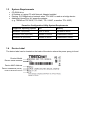
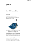
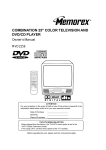
Device Label
The device label can be located on the back of the device where the power prong is found.
Product Model
Device Serial Number
Device MAC Address
Device Password (DPW)
Product Hardware Version
Product Firmware Version
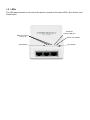
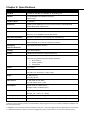
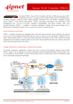
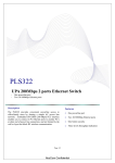
1.5 LEDs
The LED panel located on the front of the device consists of the status LEDs, Sync button, and
Reset button.
Powerline
Link/Act LED (PL)
Ethernet Link/Act
LED (1-3)
Reset Button
Power LED (PWR)
Sync Button
LED
PWR (Power)
PL (Powerline)
Note: LED color
indicates the
strength and
quality of the
powerline
connection
through the
electrical system
1-3 (Ethernet
Port)
Color
Sequence
Definition
Green
Solid
Device powered On
N/A
Off
Device powered Off
Solid
Powerline Connected (Connection Quality is Best)
Blinking
Syncing or Powerline Data Transmitting/Receiving (Connection Quality is Best)
Solid
Powerline Connected (Connection Quality is Better)
Blinking
Powerline Data Transmitting/Receiving (Connection Quality is Better)
Solid
Powerline Connected (Connection Quality is Good)
Blinking
Powerline Data Transmitting/Receiving (Connection Quality is Good)
Off
Powerline is not synced or connected
Solid
10/20 Mbps or 100/200Mbps (Half/Full Duplex) Connected (per port)
Blinking
10/20Mbps or 100/200Mbps (Half/Full Duplex) Data Transmitting/Receiving (per
port)
Off
Port Disconnected/No Ethernet Link
Green
Amber
Red
N/A
Green
N/A
Button
Action
(Sync)
Function
Initiate Sync/Connection and generate random network name/key on first
adapter (PWR LED will start blinking)
Push/Hold for 2
sec
Match network name/key on secondary or additional adapter and connect to
first adapter. (PWR LED will start blinking)
Note: The secondary or additional powerline adapter’s Sync button must also be
pushed within 2 minutes (120 sec) of pushing the Sync button of the first adapter
in order to establish connectivity.
Push/Hold for 10
sec
Reset
Push/Hold for 1
sec
Erases the network name/key
(All LEDs will turn off and turn back on)
Reset device to factory defaults (All LEDs will turn off and turn back on)
Note: Will reset to the factory default private network name “HomePlugAV”
*Note: The following factors may affect the powerline network’s connection quality:
Noise – Generated by appliances that are connected to your electrical system through power outlets that have high power
consumption requirements. (e.g. Microwaves, ovens, blow dryer, iron, dishwasher, etc.) The quality of your household
electrical wiring may also cause additional noise on your electrical system.
Distance – Long lengths of electrical wiring through your electrical system between connected powerline adapters.
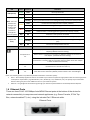
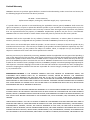
1.6 Ethernet Ports
There are three RJ-45 10/100Mbps Auto-MDIX Ethernet ports at the bottom of the device for
network connectivity to computers and network appliances (e.g. Game Console, IP Set Top
Box, network enabled TV, etc.) using the included Cat. 5 Ethernet cable.
Ethernet Ports
Chapter 2: Product Installation
At factory default settings, a pair of TPL-305E 3-Port 200Mbps Powerline AV adapters
can be installed into any room in your home or small office with a wall power outlet, without the
need for additional software or configuration. To create a simple powerline network using a pair
TPL-305E powerline adapters, simply plug one of your TPL-305E adapters into a wall power
outlet in one room and plug the other TPL-305E adapter into an available wall power outlet in
another room to establish connectivity between the two rooms.
In order to share Internet connectivity through your powerline adapters, it is ideal to
install at least one powerline adapter in the room where your modem and router are located and
connect the powerline adapter to one of your router’s LAN ports via Ethernet. Any additional
powerline adapters that are installed and connected in other rooms will then share Internet
connectivity through your router. Once the powerline adapters are connected to each other
through the electrical system, any additional devices such as computers or network appliances
(e.g. Game Console, Blu-ray player, IP Set Top Box, network enabled TV, etc.) connected to
any of your powerline adapters via Ethernet can then communicate to each other as well as
share Internet connectivity through your router.
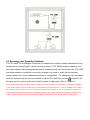
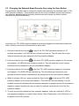
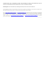
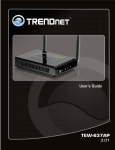
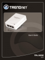
The example diagram shows a typical powerline network configuration in a home environment with 3 powerline
adapters installed in different rooms. The orange line represents the powerline connectivity established through
your home’s electrical system and the blue lines represent Cat. 5, 5e, 6 Ethernet connectivity to your network
enabled appliances such as a computer, router, or IP set top box connected to your television.
2.1 Initial Installation
The procedure describes how to create a basic powerline network between a pair of TPL-305E
powerline adapters and share Internet connection through a router to computers or network
appliances in another room.
Assuming your router is already installed and configured for Internet connectivity and the TPL305E powerline adapters are at factory default settings.
1. Plug one of the TPL-305E powerline adapters into an available wall power outlet in the room
where your router is located.
Warning: Do not plug the powerline adapter into a power strip that has surge protection. Doing so will degrade
power line performance. For best performance, plug all powerline adapters directly into a wall power outlet.
2. Connect one end of the Ethernet Cable into one of the Ethernet ports located at the bottom of
the TPL-305E and connect the other end of the Ethernet cable into one of the router’s LAN
ports.
3. Plug the second TPL-305E powerline adapter into an available wall power outlet in another
room where your computer or network appliance (e.g. Game Console, Blu-ray player, IP Set
Top Box, network enabled TV, etc.) is located.
4. Connect one end of the Ethernet Cable into one of the Ethernet ports located at the bottom of
the second TPL-305E and the other end of the Ethernet cable into the Ethernet port on your
computer or network appliance (e.g. Game Console, Blu-ray player, IP Set Top Box, network
enabled TV, etc.).
5. To verify connectivity between the TPL-305E powerline adapters, make sure that the PL LED
on each TPL-305E is on solid (Green, Amber, Red). Please refer to the LED section 1.5 for
details on the LED indicator.
6. You have successfully created a basic powerline network between a pair of TPL-305E
powerline adapters. All computers or network appliances connected to the powerline
adapters via Ethernet can now communicate to each other as well as access the Internet.
2.2 Securing your Powerline Network
The TPL-305E 3-Port 200Mbps Powerline AV Adapter has a default network name/security key
assignment of “HomePlugAV”. When connecting a pair of TPL-305E powerline adapters, both
powerline adapters will be assigned the default network/security key which allows the TPL-305E
powerline adapters to establish connectivity through your home or small office’s electrical
system without the need for additional software or configuration. For added security, the default
network name/security key can be modified using the TPL-305E Sync button
covered in the
following section or through the use of the Powerline Configuration Utility in Chapter 4.
Note: The default network name/security key assigned to the TPL-305E is “HomePlugAV”. All powerline adapters
in the same powerline network must have the same network name/security key in order to establish connectivity. If
the network name/security keys are not the same for all powerline adapters on the same powerline network, the
adapter will NOT establish connectivity. TRENDnet Powerline AV models TPL-303E, TPL-304E, TPL-305E, TPL310AP, and TPL-401E all have the same default network name/security key assignment of “HomePlugAV”.
2.3 Changing the Network Name/Security Key using the Sync Button
The procedure describes how to change the network name/security key between a pair of TPL305E powerline adapters. This procedure can also be used to establish connectivity between
two powerline adapters that are currently disconnected and change the default network
name/security key simultaneously.
Assuming your TPL-305E powerline adapters are already plugged into wall power outlets and
either currently connected or disconnected to each other.
1. Push and hold the Sync button
on one of the TPL-305E powerline adapters for 10
seconds and release it. All LEDs will turn off and turn back on. This will erase the current
network name/security key assigned to the first powerline adapter.
2. Push and hold the Sync button
on the other TPL-305E powerline adapter for 10 seconds
and release it. All LEDs will turn off and turn back on. This will erase the current network
name/security key assigned to the second powerline adapter.
3. Push and hold the Sync button
on the first TPL-305E powerline adapter for 2 seconds
and release it. The PWR LED will start blinking. This will initiate sync/connection and
generate a random network name/security key assignment to the first powerline adapter.
4. Within 2 minutes (120 sec), push and hold the Sync button
on the second TPL-305E
powerline adapter for 2 seconds and release it. The PWR LED will start blinking. This will
establish connectivity between the two powerline adapters by assigning the second powerline
adapter’s network name/security key to match the network name/security key of the first
powerline adapter.
5. To verify connectivity between the two powerline adapters, make sure that the PL LED on
each powerline adapter is on solid (Green, Amber, Red). Please refer to the LED section 1.5
for details on the LED indicator.
2.4 Adding the Powerline Adapter to an Existing Powerline Network
The procedure describes how to add the TPL-305E 3-Port 200Mbps Powerline AV Adapter to
an existing powerline network.
Assuming the two TPL-305E powerline adapters are currently connected to each other and the
third TPL-305E (Additional) powerline adapter is currently disconnected.
1. Push and hold the Sync button
on the additional TPL-305E powerline adapter for 10
seconds and release it. All LEDs will turn off and turn back on. This will erase the current
network name/security key assigned to the additional TPL-305E powerline adapter.
2. Push and hold the Sync button
on one of the two TPL-305E powerline adapters that are
currently connected to each other for 2 seconds. The PWR LED will start blinking.
3. Within 2 minutes (120 sec), push and hold the Sync button
on the additional TPL-305E for
2 seconds and release it. The PWR LED will start blinking. This will establish connectivity
between the three powerline adapters by assigning the additional TPL-305E powerline
adapter’s network name/security key to match the network name/security key of the TPL305E powerline adapters that are currently connected.
4.
To verify connectivity between the three powerline adapters, make sure that the PL LED on
each powerline adapter is on solid (Green, Amber, Red). Please refer to the LED section 1.5
for details on the LED indicator.
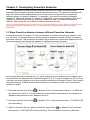
Chapter 3: Overlapping Powerline Networks
It is possible to create multiple powerline networks on the same electrical system
separated and grouped by different network names/security keys. The powerline networks will
work and communicate independently of each other which can provide security between
different groups of powerline adapters. For example, if you have five powerline adapters
(Adapter A, Adapter B, Adapter C, Adapter D, Adapter E), you can group Adapters A,B, and C
together on one powerline network and group Adapters D and E on a different powerline
network. Each group will use a different network name/security key.
Note: It is recommended that only a maximum of up to 4 powerline networks can be created per electrical system.
Any additional powerline networks above the recommended result in significant degradation in powerline
performance.
3.1 Move Powerline Adapters between different Powerline Networks
Use the procedures in Chapter 2: Product Installation, to connect one group of adapters, then
you can carry out the procedures on another group of adapters to create multiple overlapping
powerline networks. This procedure describes how to disconnect a powerline adapter from one
powerline network and connect the adapter to a different powerline network.
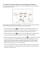
Assuming all powerline adapters are TPL-305E adapters and for reference in the diagram and
this procedure, the adapters will be labeled Adapter A, B, C, D, and E. Adapters A, B, and C are
currently connected together to form one powerline network and Adapters D and E form another
powerline network. Adapter B will be disconnected from Adapters A and C and connected to
Adapters D and E.
1. Push and hold the Sync button
on Adapter B for 10 seconds and release it. All LEDs will
turn off and turn back on. This will erase the current network name/security key assigned to
Adapter B and disconnect from Adapters A and C.
2. Push and hold the Sync button
on Adapter D for 2 seconds and release it. The PWR LED
will start blinking.
3. Within 2 minutes (120 sec), push and hold the Sync button
on Adapter B for 2 seconds
then release it. The PWR LED will start blinking. This will establish connectivity between
Adapters B, D, and E by assigning Adapter B’s network name/security key to match the
network name/security key of Adapters D and E.
4. To verify connectivity between the powerline adapters, make sure that the PL LED on each
powerline adapter is on solid (Green, Amber, Red). Please refer to the LED section 1.5 for
details on the LED indicator.
Chapter 4: Powerline Configuration Utility
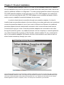
The Powerline Configuration Utility is an additional tool that allows you to centrally
manage the powerline adapters that are connected to your network. Instead of using a
randomly generated key with the Sync button, the utility allows you to manually configure the
network name/security key for a single powerline adapter or multiple adapters simultaneously.
This tool allows for easy management for multiple powerline adapters in your network.
Note:
1. Before installing and using the utility, write down the 16-digit Device Password (DPW) and MAC Address of
each TPL-305E powerline adapter as this will be required to apply changes to remote devices discovered
in the utility. This is located on the Device Label, please refer to Section 1.4.
2. Before installing and using the utility, make sure your computer in which you are installing the utility is
connected to your network and your TPL-305E adapters are also connected to your network.
3. Make sure all of the TPL-305E powerline adapters are already connected to each other using the
procedures in Chapter 2: Product Installation.
4. The utility is only compatible with Windows operating systems. For details, please refer to Section 1.3.
4.1 Software Installation
1. Insert the included CD-ROM into your computer’s CD-ROM drive.
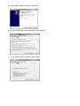
2. At the CD Autorun Prompt window, click Run Autorun.exe
3. At the CD-ROM menu window, click Install Utility.
4. At the WinPcap installer window, click Next.
Note: The Powerline Configuration Utility requires the use of the WinPcap application. If this prompt does
not appear, you may already have the WinPcap application installed. If so, please skip over to Step 10.
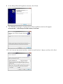
5. In the Setup Wizard window, click Next.
6. In the License Agreement window, click I Agree.
7. In the Install Options window, click Install.
8. At the Setup Wizard Completion window, click Finish.
9. The TRENDnet Powerline Configuration Utility installation window will appear
automatically. At the Setup Wizard window, click Next.
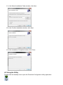
10. In the License Agreement window, check the radio button I Agree, and then click Next.
11. In the Select Installation Folder window, click Next.
12. In the Confirm Installation window, click Next.
13. At the Installation Complete window, click Close.
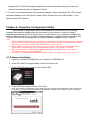
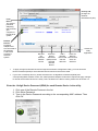
4.2 Using the Utility
Double-click the desktop icon to open the Powerline Configuration Utility application.
Privacy Tab
Change the
Network
Name/Security Key
Local
Device
The closest
powerline
adapter(s)
that connects
your
computer to
the electrical
system.
Remote
Devices
Powerline
adapters that
are connected to
the selected
Local Device
across the
electrical
system.
Closes the
utility
application.
Rename
the
selected
Remote
Device
Enter the
Device
Password
(DPW) for the
selected
Remote
Device
Scans for
Add a
Remote
Remote
Device that Devices that
were not
was not
detected
detected
To apply changes to Remote Devices through the Powerline Configuration Utility, you must enter the
Device Password (DPW) for each Remote Device located on the Device Label.
If you have not already done so, please write down the 16-digit Device Password (DPW) and
corresponding MAC Address of each TPL-305E powerline adapter as this will be required to apply changes
to remote devices discovered in the utility. This is located on the Device Label, please refer to Section 1.4.
Enter the 16-digit Device Password (DPW) for each Remote Device in the utility
1. Click one of the Remote Devices in the list.
2. Click Enter Password.
3. Type in the Device Password according to the corresponding MAC address. Then
click OK.
4. If successful, the Remote Device will have the Device Password listed next to the
device under Password.
Note: If the incorrect Device Password is entered, you will receive an error message. Click Enter
Password and try entering the password again.
5. Repeat steps 1-4 for any remaining Remote Devices.
6. Once all of the Device Passwords (DPW) are entered into the utility, changes can be
applied to the Remote Devices using the utility.
Change the Network Name/Security Key for multiple adapters using the utility
1. Click the Privacy tab.
2. Under Private Network Name, enter the desired network name/security key and click
Set All Devices.
3. At the Network Name Setting prompt window, click OK.
The current network
name/security key
assignment of the
powerline
adapter(s).
Note: If you had
previously used the
Sync button
procedure in
generating a
random network
name/security key.
This will display
“Unknown
Networkname”
Applies changes
to Local Device
only.
Note: If you
choose this
option, you will
disconnect the
Local Device
from the Remote
Devices.
Applies changes to
Local Device and
Remote devices.
Note: If you have
not entered the
DPW for all remote
devices, you will
receive an error
and the changes
will not be applied
to remote devices
without a DPW.
Chapter 5: Troubleshooting
Please reference the items below if you continue to experience difficulty with installing and
using your TPL-305E 3-Port 200Mbps Powerline AV Adapter.
Try power cycling the unit by unplugging it from the wall power outlet for 15 seconds and
plugging it back in.
If the PL LED is red indicating good quality only, try plugging the TPL-305E into another
available wall power outlet to check if you can obtain better connection quality.
Use a pin or paperclip and push and hold the Reset button for 1 second on each TPL-305E
powerline adapter. All LEDs will turn off and turn back on. This will reset the TPL-305E
powerline adapters to the default settings, network name/security key assignment
“HomePlugAV”.
The TPL-305E can provide better connectivity and performance when plugged directly into
the wall power outlet instead of a power strip or surge protector.
Connecting the TPL-305E to a power strip or surge protector may degrade network
performance or completely stop network signals.
The TPL-305E should not be used on GFI protected outlets as some outlets will filter out
powerline signals.
The TPL-305E should not be used in areas with excessive heat.
Certain florescent or incandescent lights are noise sources on the electrical and can degrade
powerline performance.
If your building has more than one circuit breaker box, the TPL-305E may not be able to
establish connectivity between different circuit breaker boxes. In this case, connect a TPL305E powerline adapter to a power outlet located on each of the circuit breaker boxes, and
then connect an Ethernet cable between the TPL-305E powerline adapters to bridge the two
circuits together. This will allow the TPL-305E powerline adapters from different circuit
breaker boxes connect to each other.
Power Saving: The device will automatically reduce power usage when the connected devices
via Ethernet are powered off, unplugged or inactive for more than 2 minutes.
Erp (EuP) Operation: Standby Mode
Disconnect the Ethernet cables from the device Ethernet ports, and after 3 minutes, the
device will enter standby mode. The Power (PWR) LED will flash every 15 seconds to
indicate that the device is currently in standby mode.
To return to active mode, reconnect the Ethernet cables to the device Ethernet ports, and the
device will re-enter active mode.
Chapter 6: Specifications
Hardware
Standards
IEEE 802.3, IEEE 802.3x, IEEE 802.3u, HomePlug® AV
Interface
3 x 10/100Mbps Auto-MDIX RJ-45 ports,
Power prong
Frequency Band
2 ~ 28 MHz
Modulation
OFDM Symbol Modulation on link synchronization, 1024/256/64/8 QAM, QPSK, BPSK, ROBO Carrier
Protocol
TDMA, and CSMA/CA
Speed
Powerline: Up to 200Mbps**
Ethernet: Up to 200Mbps (Full Duplex mode)
Utility OS Compatibility
Windows 7 (32/64-bit), Vista (32/64-bit), XP(32/64-bit)
Nodes
Up to 64 max.
Recommended: up to 16* per Powerline network
Overlapping
Powerline Networks
Up to 4 (per electrical system)
Coverage
Up to 300m (984ft.)
Security
128-Bit AES (Advanced Encryption Standard)
LED
Power (PWR), Ethernet Link/Act (1-3)
Powerline (PL) with Connection Quality Indication
Best (Green)
Better (Amber)
Good (Red)
Buttons
Sync, Reset
Dimension (L x W X H)
A: 103 x 74 x 57 mm (4.1 x 2.9 x 2.2 in.)
EU: 103 x 74 x 72 mm (4.1 x 2.9 x 2.8 in.)
Weight
A: 165 g (5.8 oz)
EU: 170 g (6.0 oz)
Power Source
A: 100~230V AC, 50~60Hz
EU: 220~240V/ 5A AC, 50Hz
Consumption
Active mode: 3.2 Watts (max.)
Standby mode: 0.9 Watts (max.)
Temperature
Operating: 0° ~ 40°C (32° ~ 104°F)
Storage: -20° ~ 70°C (-4° ~ 158°F)
Humidity
Max. 90% (non-condensing)
Certifications
CE, FCC
* Maximum of 16 adapters (nodes) recommended for streaming video across your network. Additional adapters may
decrease performance.
** 200Mbps is the maximum theoretical Powerline data rate. Actual throughput will vary depending on environment.
*** Networked Powerline devices need to be plugged into power outlets that are on the same electrical system.
Limited Warranty
TRENDnet warrants its products against defects in material and workmanship, under normal use and service, for
the following lengths of time from the date of purchase.
TPL-305E – 3 Years Warranty
AC/DC Power Adapter, Cooling Fan, and Power Supply carry 1 year warranty.
If a product does not operate as warranted during the applicable warranty period, TRENDnet shall reserve the
right, at its expense, to repair or replace the defective product or part and deliver an equivalent product or part to
the customer. The repair/replacement unit’s warranty continues from the original date of purchase. All products
that are replaced become the property of TRENDnet. Replacement products may be new or reconditioned.
TRENDnet does not issue refunds or credit. Please contact the point-of-purchase for their return policies.
TRENDnet shall not be responsible for any software, firmware, information, or memory data of customer contained in, stored on, or integrated with any products returned to TRENDnet pursuant to any warranty.
There are no user serviceable parts inside the product. Do not remove or attempt to service the product by any
unauthorized service center. This warranty is voided if (i) the product has been modified or repaired by any unauthorized service center, (ii) the product was subject to accident, abuse, or improper use (iii) the product was
subject to conditions more severe than those specified in the manual.
Warranty service may be obtained by contacting TRENDnet within the applicable warranty period and providing a
copy of the dated proof of the purchase. Upon proper submission of required documentation a Return Material
Authorization (RMA) number will be issued. An RMA number is required in order to initiate warranty service support for all TRENDnet products. Products that are sent to TRENDnet for RMA service must have the RMA number
marked on the outside of return packages and sent to TRENDnet prepaid, insured and packaged appropriately for
safe shipment. Customers shipping from outside of the USA and Canada are responsible for return shipping fees.
Customers shipping from outside of the USA are responsible for custom charges, including but not limited to, duty, tax, and other fees.
WARRANTIES EXCLUSIVE: IF THE TRENDNET PRODUCT DOES NOT OPERATE AS WARRANTED ABOVE, THE
CUSTOMER’S SOLE REMEDY SHALL BE, AT TRENDNET’S OPTION, REPAIR OR REPLACE. THE FOREGOING
WARRANTIES AND REMEDIES ARE EXCLUSIVE AND ARE IN LIEU OF ALL OTHER WARRANTIES, EXPRESSED OR
IMPLIED, EITHER IN FACT OR BY OPERATION OF LAW, STATUTORY OR OTHERWISE, INCLUDING WARRANTIES OF
MERCHANTABILITY AND FITNESS FOR A PARTICULAR PURPOSE. TRENDNET NEITHER ASSUMES NOR AUTHORIZES
ANY OTHER PERSON TO ASSUME FOR IT ANY OTHER LIABILITY IN CONNECTION WITH THE SALE, INSTALLATION
MAINTENANCE OR USE OF TRENDNET’S PRODUCTS.
TRENDNET SHALL NOT BE LIABLE UNDER THIS WARRANTY IF ITS TESTING AND EXAMINATION DISCLOSE THAT THE
ALLEGED DEFECT IN THE PRODUCT DOES NOT EXIST OR WAS CAUSED BY CUSTOMER’S OR ANY THIRD PERSON’S
MISUSE, NEGLECT, IMPROPER INSTALLATION OR TESTING, UNAUTHORIZED ATTEMPTS TO REPAIR OR MODIFY, OR
ANY OTHER CAUSE BEYOND THE RANGE OF THE INTENDED USE, OR BY ACCIDENT, FIRE, LIGHTNING, OR OTHER
HAZARD.
LIMITATION OF LIABILITY: TO THE FULL EXTENT ALLOWED BY LAW TRENDNET ALSO EXCLUDES FOR ITSELF AND ITS
SUPPLIERS ANY LIABILITY, WHETHER BASED IN CONTRACT OR TORT (INCLUDING NEGLIGENCE), FOR INCIDENTAL,
CONSEQUENTIAL, INDIRECT, SPECIAL, OR PUNITIVE DAMAGES OF ANY KIND, OR FOR LOSS OF REVENUE OR
PROFITS, LOSS OF BUSINESS, LOSS OF INFORMATION OR DATE, OR OTHER FINANCIAL LOSS ARISING OUT OF OR IN
CONNECTION WITH THE SALE, INSTALLATION, MAINTENANCE, USE, PERFORMANCE, FAILURE, OR INTERRUPTION
OF THE POSSIBILITY OF SUCH DAMAGES, AND LIMITS ITS LIABILITY TO REPAIR, REPLACEMENT, OR REFUND OF THE
PURCHASE PRICE PAID, AT TRENDNET’S OPTION. THIS DISCLAIMER OF LIABILITY FOR DAMAGES WILL NOT BE
AFFECTED IF ANY REMEDY PROVIDED HEREIN SHALL FAIL OF ITS ESSENTIAL PURPOSE.
Governing Law: This Limited Warranty shall be governed by the laws of the state of California.
Some TRENDnet products include software code written by third party developers. These codes are subject to the
GNU General Public License ("GPL") or GNU Lesser General Public License ("LGPL").
Go to http://www.trendnet.com/gpl or http://www.trendnet.com Download section and look for the desired
TRENDnet product to access to the GPL Code or LGPL Code. These codes are distributed WITHOUT WARRANTY
and are subject to the copyrights of the developers. TRENDnet does not provide technical support for these
codes. Please go to http://www.gnu.org/licenses/gpl.txt or http://www.gnu.org/licenses/lgpl.txt for specific
terms of each license.
PWP05202009v2