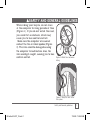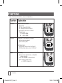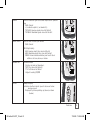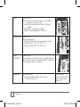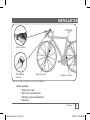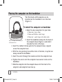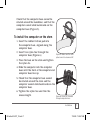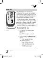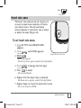
1
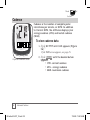
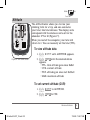
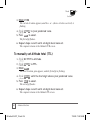
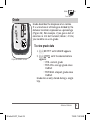
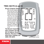
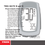
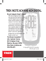
Trek Incite ACH and ACH Digital
Bicycle Computer Owner’s Manual
This manual explains the installation and use of the Trek Incite ACH
and ACH Digital bicycle computers.
Please read this manual carefully
and save it for future reference.
If you do not understand the
information in this manual, or you
have a question about your Incite
ACH computer that this manual
does not cover, consult your Trek
dealer. If you have a question or
problem that your Trek dealer can’t
handle, contact us at:
Trek Bicycle Corporation
Attn: Customer Service
801 W. Madison Street
Waterloo, Wisconsin 53594
http://www. trekbikes.com
920.478.4670
© Copyright Trek Bicycle Corporation
2006 All rights reserved
06 Incite ACH 07_13.indd 1
7/14/06 7:25:51 AM
Contents
Safety and general guidelines.......................................................... 1
Functions.......................................................................................... 2
Installation........................................................................................ 5
Placing the computer on the handlebar...................................... 6
Placing the magnet and sensors.................................................. 8
Positioning of the heart rate strap ........................................... 11
Easy setup (ReSet)..................................................................... 12
ReStart- Getting ready to ride........................................................ 17
Additional information................................................................... 18
Troubleshooting.............................................................................. 19
Replacing the battery..................................................................... 20
Advanced features........................................................................... 22
Units........................................................................................... 23
Clock........................................................................................... 24
Stopwatch................................................................................... 25
Wheel size and setting a second wheel...................................... 26
Speed.......................................................................................... 30
Odometer.................................................................................... 31
Cadence....................................................................................... 32
Altitude....................................................................................... 33
Grade.......................................................................................... 35
Heart rate................................................................................... 36
Heart rate zone........................................................................... 37
Limited Warranty............................................................................ 38
ii
06 Incite ACH 07_13.indd 2
7/14/06 7:25:52 AM
Safety and general guidelines
While riding your bicycle, do not stare
at the computer for long periods of time
(Figure 1). If you do not watch the road,
you could hit an obstacle, which may
cause you to lose control and fall.
Make sure the computer wire cannot
contact the tire or wheel spokes (Figure
2). The wire could be damaged causing
the computer to malfunction. Also, the
wire could get caught, causing you to lose
control and fall.
Figure 1- Watch the road when
riding.
Figure 2- Keep the wire out of
the spokes
Safety and General guidelines
06 Incite ACH 07_13.indd 1
7/14/06 7:25:52 AM
Functions
Table 1- Function abbreviations, names and explanations
Function Explanation
Altitude
Height relative to sea level.
CUR- Current
TRP- Trip (since last Restart)
TTL- Total gained since last ReSet
MAX- Highest value since last ReSet
Effective range:
FT -1250 to +30180
M
-381 to +9200
Cadence
Revolutions of the crankset per minute
Displays in whole numbers
Highest reading: 240.
ACH Digital (only)
AVG- Average cadence since last Restart
MAX- Maximum cadence since last Restart
Clock
Time of day
Displays in hours and minutes, or stopwatch
showing seconds.
12-hour with AM/PM or 24-hour format
Highest reading: 23:59 (clock)
or 23:59:59 (stopwatch)
Functions
06 Incite ACH 07_13.indd 2
7/14/06 7:25:53 AM
Grade
Ratio of elevation gain to distance expressed as percentage.
CUR- Current
+/- indicates uphill (+) or downhill (-)
TRP AVG- Average grade since last Restart
TRP MAX- Maximum grade since last Restart
Heart rate
Rate of heart in beats per minute
CUR- Current
ACH Digital (only)
AVG- Average heart rate since last ReSet
MAX- Maximum heart rate since last Restart
ZONE- Arrows indicate whether your heart rate is
within a set zone, above, or below
Odometer
Distance ridden
Displays in miles or kilometers.
TRP- Trip (since last Restart)
TTL- Total since last ReSet
Highest reading: 99,999
Pacer
Always displays
Indicates whether current speed is above or below
average speed
Displayed by arrow pointing up (above) or down
(below).
Functions
06 Incite ACH 07_13.indd 3
7/14/06 7:25:54 AM
Speed
Always displays
Current speed of the bicycle in miles per hour (MPH)
or kilometers per hour (KPH)
AVG- Average speed since last Restart, displayed
to tenths.
MAX- Highest value since last Restart
Highest readings: 80.5 mph or 129.6 kph
Temperature
Always displays
Current temperature
Displayed in Fahrenheit or Celsius in whole numbers.
Lowest reading: -2° F +/-2°, -19° C +/-1°
Highest reading: 140° F +/-2°, 60° C +/-1°
Wheel
selection
Always displays
The computer can calculate from two programmed wheel
sizes, and this indicates which wheel setting is currently in
use by computer, Wheel 1 or Wheel 2
BACKLIGHT
ACH Digital (only)
Provides backlight to display for 5 seconds.
To activate, Push Set.
Note: Backlight
requires power; excessive use will reduce
battery life.
Functions
06 Incite ACH 07_13.indd 4
7/14/06 7:25:55 AM
Installation
Stem mount
Handlebar
mount
Speed sensor
Cadence sensor
Figure 3- Location on bicycle of sensors and computer
Tools
•
•
•
•
needed:
Electrical tape
Slot-type screwdriver
Phillips-type screwdriver
Scissors
Installation
06 Incite ACH 07_13.indd 5
7/14/06 7:25:56 AM
Placing the computer on the handlebar
The Trek Incite ACH computer can be
mounted on the handlebar or on the stem
(Figure 3).
To install the computer on handlebar
1. Select the bar clamp that fits your bike.
31.8mm bars: large clamp
25.4mm and 26.0mm: small clamp
22.2mm bar: small clamp with rubber shim
2. Insert the handlebar clamp into the back of
the computer base (Figure 4) and slide it
towards the front of the base.
3. Insert the rubber friction pad into the computer base, aligned
across the computer base.
Figure 4- Clamp and friction pad
in computer base
4. With the wire pointing toward the front of the bike, wrap the bar
clamp around the handlebar.
5. Insert the screw through the washer and into the computer base.
6. Tighten the screw until the computer base cannot rotate on the
handlebar.
7. Slide the computer into the computer base until the front of the
computer and computer base line up.
Installation
06 Incite ACH 07_13.indd 6
7/14/06 7:25:57 AM
Check that the computer base cannot be
rotated around the handlebar, and that the
computer cannot slide backwards on the
computer base (Figure 5).
To install the computer on the stem
1. Insert the rubber friction pad into
the computer base, aligned along the
computer base.
2. Insert two nylon ties through the
computer base (Figure 6).
3. Place the base on the stem and tighten
the nylon tie.
Figure 5- Make sure the computer cannot be bounced off.
4. Slide the computer into the computer
base until the front of the computer and
computer base line up.
5. Check that the computer base cannot
be rotated around the stem and the
computer cannot slide backwards on the
computer base.
6. Tighten the nylon ties and trim the
excess length.
Figure 6- Nylon tie threaded
through computer base
Installation
06 Incite ACH 07_13.indd 7
7/14/06 7:25:57 AM
Placing the magnet and sensors
The wheel magnet must be aligned so that
it passes across the sensor. As the magnet
passes the sensor, it must be no further from
the sensor than 1 to 3mm (1/32 to 1/8 inch).
The wheel magnet has a ‘T’ shaped slot with
two configurations: round spokes and flat or
bladed spokes (Figure 7).
The cadence sensor, with the wire, mounts
near the crankset. It must be aligned so that
the magnet passes within 1-3mm, and in line
with the small line on the sensor (Figure 8).
Figure 7- Installing magnet on
round or oval spokes
To install the wheel magnet
1. Remove the screw from the magnet.
2. Slide the slot in the back of the magnet
over the spoke.
For a flat or bladed spoke, start the spoke near
the end where the spoke is round, and align the
top of the ‘T’ with the spoke as you slide the
magnet up the blade (Figure 7).
Figure 8- Magnet placed on
crankarm, aligned with sensor on
chainstay
3. Thread the screw into the magnet until it
is snug against the spoke.
Installation
06 Incite ACH 07_13.indd 8
7/14/06 7:25:58 AM
To install the sensor
These instructions are written for the
cadence sensor, which goes on the frame’s
left chainstay. The instructions apply
equally to installing the ACH Digital
cadence sensor or the wheel sensor on the
fork- where there is no wire on the sensor.
1. Align the sensor with the magnet.
The magnet must pass across the line on the
sensor (Figure 9).
2. Orient the sensor so that the clearance
between the sensor and the magnet is
between 1 to 3mm.
The sensor can be rotated around the crank
about 45 degrees.
If needed, the sensor and magnet can be moved
up or down the crank and bike frame to change
the amount of clearance.
1.0 3.0mm
Figure 9- Magnet alignment and
clearance
3. For a wireless sensor, install the rubber
“foot” in the sensor (Figure 10).
The ACH Digital has an integrated rubber foot.
4. Attach the sensor with nylon ties, but
do not fully tighten.
Figure 10- Wireless sensor, foot,
and fork blade
Installation
06 Incite ACH 07_13.indd 9
7/14/06 7:25:59 AM
5. With the computer in the computer base,
check the alignment of the sensor and magnet
by spinning the wheel and noting if the
computer is displaying cadence (or for the
wheel sensor, speed).
If the computer shows cadence (RPM) or current
speed, the sensor is reading the magnet. If the
computer is not displaying a value, realign the sensor
and magnet until one is displayed.
6. Tighten the nylon ties and trim the excess
length (Figure 11).
Figure 11- Trim excess nylon tie
length
10
Installation
06 Incite ACH 07_13.indd 10
7/14/06 7:25:59 AM
Positioning of the heart rate strap
To monitor your pulse, or heart rate, you
must be wearing the heart rate strap. The
strap senses each contraction, or beat, of
your heart. The beat is sensed electrically,
so proper location of the strap is important
to attain the strongest signal.
To be near to your heart, wear the heart
rate strap around your lower rib cage, just
under the breasts (Figure 12).
For best results, the contact between the
sensor and your skin should be moist.
Wet the ribbed section of the sensor before
putting it on. Once you start riding, this
area will stay moist from perspiration.
Figure 12- Position of the heart
rate strap
Installation
06 Incite ACH 07_13.indd 11
11
7/14/06 7:25:59 AM
Easy setup (ReSet)
The computer must be set, or
“programmed,” so that it gives its
readout in the units you prefer, and so
that it calculates with the correct wheel
size.
Mode
Using the buttons
Scroll
Set
Figure 13- Buttons on the Incite
ACH computer
12
When setting the computer, there are
three ways to use the buttons:
Push- touch once
Cycle- push repeatedly as needed
Hold- push and hold in for two
or three seconds
To set the ACH, you must use the
four buttons (Figure 13) in a specific
sequence:
Set• (button on the right)
•Mode (button on the left)
Scroll (two bottom buttons, push
either one- the computer will
scroll in a different direction)
Easy setup (ReSet)
06 Incite ACH 07_13.indd 12
7/14/06 7:26:00 AM
Set
Mode
Scroll
Choose a method to ReSet the computer:
• Push any button to wake the
computer from shipping mode
• Push the ReSet button (AC) on the
back of the computer
• Install a new battery
The Wheel select icon appears with a tire
size: 700-23 (Figure 14).
INCITE
ACH
To set the wheel size
1. Cycle Scroll to your preferred wheel size Figure 14- Tire size screen
(options are shown on Table 2).
Table 2- Wheel size selections
2. Push Set• to select.
The computer displays KMH. Continue “To set
Units and Time” on the next page.
To set a custom value, or set the second wheel
size, see pages 26-29.
(last setting)
650-23
700-20
26-1.50
700-23
26-1.90
700-25
26-1.95
700-28
26-2.0
700-32
26-2.1
700-35
26-2.2
700-38
2075 (custom)
Easy setup (ReSet)
06 Incite ACH 07_13.indd 13
13
7/14/06 7:26:01 AM
Set
Mode
Scroll
To set Units and Time
This setting tells the computer which conversion to use: metric
or SAE (“English”), which clock style to use (12-hour or 24-hour)
and sets the time.
1. Cycle Scroll to your preferred setting:
• MPH for miles
• KPH for kilometers
2. Push Set• to choose your setting.
“F” (Figure 15) appears.
3. Cycle Scroll to your preferred temperature setting:
• F for Fahrenheit
• C for Celsius
4. Push Set• to choose your setting.
“12” flashes.
5. Cycle Scroll to your preferred clock
setting:
• 12 for 12-hour clock
• 24 for 24-hour clock
Figure 15- Set Units screen items
(which show up one at a time
during set-up)
6. Push Set• to choose your setting.
The hour flashes:
• “12” (12-hour)
• “0” (24-hour)
1414
Easy setup (ReSet)
06 Incite ACH 07_13.indd 14
7/14/06 7:26:02 AM
Set
Mode
Scroll
9. Cycle Scroll to the hour:
• 1, 2, 3, etc. from 1A through 12P (for 12-hour clock)
• 1, 2, 3, etc. through 24 (for 24-hour clock)
10. Push Set• to choose your setting.
“00” flashes.
11. Cycle Scroll to the minute:
• 00, 01, 02, 03, etc. through 59
12. Push Set• to choose your setting.
The screen will show one of two things:
• SPD - you are ready to ride. However, your computer has many other
features; see the Advanced Features section on pages 22-37.
• PAIR? - see next section.
Pairing (ACH Digital only)
The ACH Digital computer uses a wireless system where the
computer reads radio signals from the speed, cadence, or heart
rate sensors. For the computer to differentiate the signals, the
computer must be paired to the correct sensor.
To PAIR the computer
Only activate one sensor at a time. Until Pairing for a given
mode (Speed, Cadence, Heart Rate) is completed, the computer
cannot tell one signal from another.
Easy setup (ReSet)
06 Incite ACH 07_13.indd 15
15
7/14/06 7:26:03 AM
Set
Mode
Scroll
1. Cycle •Mode to SPEED.
The PAIR? signal appears.
2. Make the wheel sensor send a signal (spin the bicycle wheel).
3. Place the computer within 3 feet (1 meter) of the sensor and hold
the Set• button.
The screen changes to PAIR....
4. Release the Set• button.
The computer works for a moment, then returns to the SPEED screen.
If the ERROR screen appears, there may be a
problem:
• There is interference (proximity to another
signal)
Move away from other computers, cell phones, etc.
• The battery in the sensor is weak
Replace the battery in the sensor- see page 20.
• There is too much distance between the
computer and sensor.
Move the computer closer to the sensor.
5. Repeat steps 1-4 in CAD mode (Cadence) while spinning the
crankset.
6. Repeat steps 1-4 in HR mode (Heart Rate) while wearing the heart
rate strap.
16
Easy setup (ReSet)
06 Incite ACH 07_13.indd 16
7/14/06 7:26:03 AM
Set
Mode
Scroll
ReStart- Getting ready to ride
Your computer stores data for two
intervals- since last ReSet and since last
ReStart. ReSet sets ALL data to zero.
ReStart sets only the Trip data to zero.
To ReStart (set the Trip data to zero)
The trip data includes five modes for seven
total sets:
• ODOMETER TRP
• SPEED
AVG, MAX
• ALTITUDE
TRP, MAX
• GRADE
AVG
• CLOCK (Stopwatch)
Figure 16- Stopwatch mode
showing time with seconds
1. Cycle •Mode to CLOCK.
2. Cycle Scroll to Stopwatch (Figure 16).
3. Hold Set• and then at the same time, Hold •Mode.
Stopwatch setting reads ‘00:00.00’ indicating trip mode is set to zero.
To start the trip modes
Any input of distance or cadence will start the stopwatch and
other trip modes.
ReStart
06 Incite ACH 07_13.indd 17
17
7/14/06 7:26:04 AM
Set
Mode
Scroll
Additional information
Changing mode
Once the computer is programmed and installed, it is very easy
to use. To change to different modes (functions), simply Cycle
the •Mode button on the left of the computer until the desired
function appears, shown by the spelled name of the function. To
move within that function, Cycle the Scroll buttons.
Removing the computer from the computer base
The computer is held on its base by a flexible snap. To remove
the computer, press firmly on the computer (not on the base) in a
rearward direction.
Using the computer in wet weather
Bicycle computers function on electricity. If the electrical contacts
between the computer and its base become saturated, the
electrical signals may become irregular or interrupted entirely.
18
Additional Information
06 Incite ACH 07_13.indd 18
7/14/06 7:26:05 AM
Troubleshooting
The Incite ACH computer is designed to be easy to install and
maintain. However, computers occasionally have problems. Table
3 shows some possible problems, causes, and solutions:
Table 3- Common problems and solutions
Blank screen
Computer is in shipping mode. Push a button.
Battery is dead, or installed incorrectly. Reinstall good battery.
Erratic data
Magnet misaligned or too far away. Re-adjust magnet and sensor placement.
Battery power is low. Replace battery.
No current speed
Speed is incorrect.
Magnet misaligned or too far away. Re-adjust magnet and sensor placement.
Wheel size is incorrect. ReSet computer.
Sensor is not reading magnet properly. Readjust magnet and sensor alignment.
No cadence
Magnet is not reading sensor properly. Readjust magnet and sensor alignment.
Contacts between computer and base are not touching because computer is not
on base. Reinstall.
No heart rate
Heart rate strap battery power is low. Replace battery.
Heart rate strap is not contacting skin. Moisten and reposition.
Troubleshooting
06 Incite ACH 07_13.indd 19
19
7/14/06 7:26:05 AM
INCITE
Replacing the battery
If the computer is giving erratic information,
a computer or sensor battery may be running
low on power (normally accompanied by the
low battery icon, Figure 17). Replace the
batteries whenever the computer malfunctions, or every 6 months. Take an old battery
to the store with you, but this is the generic
description for the proper battery:
ACH computer and heart rate strap
• CR2032, lithium cell, 3 volts
ACH wheel sensor
• 23 AE 12v
Figure 17- Low battery icon
ACH Digital- computer, sensors, heart
rate strap
• CR2032, lithium cell, 3 volts
When the battery is removed, the computer automatically resets
function totals to Zero. After installing a new battery, you can
manually set your totals, but you must note those values before
removing the battery. With the ACH Digital, you will have to
again perform the Pairing procedure.
Replacing the battery in the speed sensor, cadence sensor, or heart rate strap
follows the same basic procedure.
20
ACH
Replacing the Battery
06 Incite ACH 07_13.indd 20
7/14/06 7:26:06 AM
To replace the computer battery
1. Remove the computer from its base.
2. Identify the battery cover, with its deep
slot (a similar battery cover is found on
the back, or skin-side, or the heart rate
strap).
3. Insert a large coin into the slot and rotate
in a counter-clockwise direction about
one-quarter turn (Figure 18).
4. Lift the battery cover, exposing the
battery.
Be careful to avoid losing the rubber O-ring seal.
Figure 18- Removing battery
cover
5. Remove the old battery.
It may be possible to shake the battery out.
Otherwise, carefully pry the battery up with a thin
tool or knife blade.
6. Insert the new battery with the ‘cross’ and
identifying label pointing up (Figure 19).
7. Replace the battery cover (and O-ring seal)
and turn one-quarter turn clockwise.
Figure 19- The ‘cross’ on the battery points up
Replacing the battery
06 Incite ACH 07_13.indd 21
21
7/14/06 7:26:07 AM
Advanced features
The ACH computer has many advanced functions and features.
These include:
Units........................................................................................... 23
Clock........................................................................................... 24
Stopwatch................................................................................... 25
Wheel size and setting a second wheel...................................... 26
Speed.......................................................................................... 30
Odometer.................................................................................... 31
Cadence....................................................................................... 32
Altitude....................................................................................... 33
Grade.......................................................................................... 35
Heart rate................................................................................... 36
Heart rate zone........................................................................... 37
22
06 Incite ACH 07_13.indd 22
7/14/06 7:26:08 AM
Units
This setting tells the computer which conversion to use: metric
or SAE (“English”).
To set Units
1. Cycle •Mode to ODOMETER.
2. Cycle Scroll to TRP.
3. Hold Set•.
“KMH” appears.
4. Cycle Scroll to your preferred setting:
• MPH for miles
• KPH for kilometers
5. Push Set• to choose your setting.
“F” appears.
6. Cycle Scroll to your preferred temperature setting:
• F for Fahrenheit
• C for Celsius
7. Push Set• to select.
The screen returns to TRP.
Advance features
06 Incite ACH 07_13.indd 23
23
7/14/06 7:26:08 AM
Mode
Set
Scroll
Clock
To set Clock
1. Cycle •Mode to CLOCK
2. Hold Set•
“12” (Figure 14) flashes.
3. Cycle Scroll to your preferred clock setting:
• 12 for 12-hour clock
• 24 for 24-hour clock
4. Push Set• to choose your setting.
The hour flashes:
“12” (12-hour) or “0” (24-hour)
5. Cycle Scroll to the hour:
• 1, 2, 3, etc. from 1A through 12P (for 12-hour clock)
• 1, 2, 3, etc. through 24 (for 24-hour clock)
6. Push Set• to choose your setting.
“00” flashes.
7. Cycle Scroll to the minute:
• 1, 2, 3, etc. through 60
8. Push Set• to choose your setting.
The screen returns to Time.
24
Advanced features
06 Incite ACH 07_13.indd 24
7/14/06 7:26:09 AM
Set
Mode
Scroll
Stopwatch
In addition to the clock function, your
computer also works like a stopwatch,
keeping track of hundredths of seconds for
up to 24 hours. At 24 hours, the stopwatch
restarts at 0.
To start the stopwatch
1. Cycle •Mode to CLOCK.
2. Cycle Scroll.
“00:00.00” appears (instead of Zero, Figure 20
shows a time).
Figure 20- Stopwatch mode
showing time with seconds
3. Spin the front wheel, either by hand or by
riding the bike.
The stopwatch starts automatically when the wheel turns. It also turns off
automatically if the wheel quits turning for 3 seconds.
Advanced features
06 Incite ACH 07_13.indd 25
25
7/14/06 7:26:10 AM
Set
Mode
Scroll
Wheel size
Your computer can read two different sizes of
wheels on two different bikes, such as your
road bike and mountain bike. Each wheel
size can be custom set for greater accuracy.
The totals for each wheel are cumulative
(ODOMETER TTL).
To set the second wheel size
1. Cycle •Mode to SPEED.
Figure 21- Wheel selection icons
Table 4- Wheel size selections and corresponding numerical value
26
700-20
2086
650-23
700-23
2096
26-1.50
2010
700-25
2105
26-1.90
2045
700-28
2136
26-1.95
2050
700-32
2155
26-2.0
2055
700-35
2168
26-2.1
2068
700-38
2180
26-2.2
2075
2. Hold Set•.
The wheel selection icon appears (Figure 21).
If PAIR? appears, see page 16.
3. Cycle Set• to a wheel:
• Wheel 1 is a circle
• Wheel 2 is a circle inside a
semi-circle
4. Push Scroll to select.
A number representing wheel size appears.
5. Cycle Scroll to your preferred wheel
size (options are shown on Table 4).
6. Push • Mode to select.
The computer returns to SPD.
Advanced features
06 Incite ACH 07_13.indd 26
7/14/06 7:26:11 AM
Set
Mode
Scroll
To set a custom wheel size
1. Cycle •Mode to SPEED.
2. Hold Set•.
The wheel selection icon appears.
3. Cycle Set• to a wheel:
• Wheel 1 is a circle
• Wheel 2 is a circle inside a semi-circle
4. Push Scroll to select.
A number representing tire size appears.
5. Cycle Scroll to the 4-digit number (e.g. “2155”).
6. Push Set•.
The first digit flashes.
7. Cycle Scroll to your preferred setting:
• 0, 1, or 2
8. Push Set• to choose your setting.
The second digit flashes.
9. Repeat until you have selected your preferred 4-digit number.
10. Push •Mode to return to the SPEED screen.
The computer returns to SPD.
Advanced features
06 Incite ACH 07_13.indd 27
27
7/14/06 7:26:11 AM
Set
Mode
Scroll
To measure rollout for wheel size
Table 1 approximates the circumference of
each tire size. Instead of using an approximation, you can measure the actual circumference of your wheel. You need a helper, your
bike, and a smooth floor with enough room
to roll the bike about 7 feet (245 cm) in a
straight line.
1. With the valve stem of the front wheel directly
over the floor Figure 22), sit on the bike.
Figure 22- Measuring rollout for
wheel size
2. Have your helper mark the floor at the valve
stem.
3. While you sit on the bike, have the helper roll
the bike forward one revolution of the wheel, so
that the valve stem is again directly over the floor.
4. Mark the new location of the valve stem.
5. Measure the distance between the marks, in millimeters.
If you can only measure in inches, convert to millimeters by multiplying by 25.4.
6. Use the result to program your computer, following the instructions on page 25.
28
Advanced features
06 Incite ACH 07_13.indd 28
7/14/06 7:26:12 AM
Set
Mode
Scroll
To select the wheel size
1. Cycle •Mode to ODOMETER.
2. Cycle Scroll to TRP.
3. Hold both left and right Scroll buttons
to change to your preferred setting
(Figure 23):
• Wheel 1
• Wheel 2
The computer returns to the TRP screen.
INCITE
MPH
F
ODO
Figure 23- Wheel icons
ACH
Advanced features
06 Incite ACH 07_13.indd 29
29
7/14/06 7:26:13 AM
Set
Mode
Scroll
Speed
In addition to the current speed which is
always displayed, there are other SPEED
features which you can access, shown below.
To view speed data
1. Cycle •Mode until SPEED appears
(Figure 24).
If the PAIR? screen appears, see page 16.
Figure 24- SPEED screen
30
2. Cycle Scroll until the desired datum
appears:
• AVG - average speed
• MAX- maximum speed
• Pacer indicates if current speed is
above or below AVG (Figure 24).
Advanced features
06 Incite ACH 07_13.indd 30
7/14/06 7:26:14 AM
Set
Mode
Scroll
Odometer
By default, the odometer on a new or ReSet computer always starts
at ‘0’. However, the odometer can be manually set so you don’t have
to start at zero.
To set Odometer total (TTL)
1. Cycle •Mode to ODOMETER (Figure
25).
2. Cycle Scroll to TTL.
3. Hold Set•.
The first digit of five flashes.
4. Cycle Scroll to your preferred value.
5. Press Set• to select.
The next digit flashes.
Figure 25- ODOMETER screen
5. Repeat steps 4 and 5 until all digits have
been selected.
After the last digit is selected, the computer returns to the SPEED screen.
If the PAIR screen appears, see page 16.
Advanced features
06 Incite ACH 07_13.indd 31
31
7/14/06 7:26:15 AM
Set
Mode
Scroll
Cadence
INCITE
Cadence is the number of complete pedal
revolutions per minute, or RPM. In addition
to Current RPM, the ACH also displays your
average cadence (AVG) and fastest cadence
(MAX).
To view cadence data
ACH
Figure 26- CADENCE screen
32
1. Cycle •Mode until CAD appears (Figure
26).
If the PAIR screen appears, see page 16.
2. Cycle Scroll until the desired datum
appears:
• CUR- current cadence
• AVG - average cadence
• MAX- maximum cadence
Advanced features
06 Incite ACH 07_13.indd 32
7/14/06 7:26:16 AM
Set
Mode
Scroll
Altitude
The ACH altimeter allows you to view your
climbing total for a trip, and also calculates
your total, like total distance. The display units
correspond with the distance units set for the
odometer: FT or M (Figure 27).
When you restart the computer, your total will
return to 0. You can manually set the total (TTL).
To view altitude data
1. Cycle •Mode until ALTITUDE appears.
Figure 27- ALTITUDE screen
2. Cycle Scroll until the desired datum
appears
• TTL- total altitude gain since ReSet
• CUR- current altitude
• TRP- altitude gain since last ReStart
• MAX- maximum altitude
To set current altitude (CUR)
1. Cycle •Mode to ALTITUDE.
2. Cycle Scroll to CUR.
Advanced features
06 Incite ACH 07_13.indd 33
33
7/14/06 7:26:17 AM
Set
Mode
Scroll
3. Hold Set•.
The current elevation appears, and the + or - (above or below sea level) is
flashing.
4. Cycle Scroll to your preferred value.
5. Push Set• to select.
The first digit flashes.
6. Repeat steps 4 and 5 until all digits have been set.
The computer returns to the Altitude CUR screen.
To manually set Altitude total (TTL)
1. Cycle •Mode to Altitude.
2. Cycle Scroll to TTL.
3. Hold Set•.
The total elevation gain appears, and the first digit is flashing.
4. Cycle Scroll until the first digit shows your preferred value.
5. Push Set• to select.
The next digit flashes.
6. Repeat steps 4 and 5 until all digits have been set.
The computer returns to the Altitude TTL screen.
34
Advanced features
06 Incite ACH 07_13.indd 34
7/14/06 7:26:18 AM
Set
Mode
Scroll
Grade
Grade describes the steepness of an incline.
It is a function of altitude gain divided by the
distance travelled, expressed as a percentage
(Figure 28). For example, if you gain 6 feet of
elevation in 100 feet traveled (183cm / 47.2m),
you would be on a 6% grade.
To view grade data
1. Cycle •Mode until GRADE appears.
Figure 28- GRADE screen
2. Cycle Scroll until the desired datum
appears:
• CUR- current grade
• TRP AVG- average grade since
ReStart
• TRP MAX- steepest grade since
ReStart
Grade data is only stored during a single
trip.
Advanced features
06 Incite ACH 07_13.indd 35
35
7/14/06 7:26:18 AM
Set
Mode
Scroll
Heart rate
The ACH computer also functions as a
wireless heart rate monitor, and can display
advanced heart rate data when the heart rate
icon is displayed (Figure 29). These data are
all erased when the Trip Data is erased.
For the ACH Digital (only): In this wireless
system, the computer must recognize a radio
signal sent by the heart rate strap. To receive
the correct signal, the computer must be
“paired” to the heart rate strap. See page 16.
Figure 29- Heart rate and heart
rate icon
To view heart rate data
1. Cycle •Mode until HEART RATE
appears.
If the PAIR screen appears, see page 16.
2. Cycle Scroll until the desired datum
appears:
• CUR- current heart rate
For ACH Digital (only)
• AVG - average heart rate
• MAX - maximum heart rate
• ZONE (see next page)
36
Advanced features
06 Incite ACH 07_13.indd 36
7/14/06 7:26:19 AM
Set
Mode
Scroll
Heart rate zone
INCITE
The heart rate zone can be set to give you
an easy-to-read visual indicator of where
your heart rate is. The Up and Down
arrows indicate if your heart rate is above
or below the zone (Figure 30).
To set heart rate zones
ACH
1. Cycle •Mode until HEART RATE
appears.
2. Cycle Scroll until ZONE appears.
Figure 30- Heart rate zone
3. Hold Set•
SET ZONE appears.
Then the Up arrow appears and the first digit flashes.
4. Cycle Scroll to change the first digit.
5. Push Set• to select
The next digit flashes.
6. Repeat until the high value is selected.
The Down arrow appears, and the first digit flashes.
7. Repeat steps 4-6 to set the lower limit value.
The screen returns to ZONE.
Advanced features
06 Incite ACH 07_13.indd 37
37
7/14/06 7:26:21 AM
Limited Warranty
Trek Bicycle Corporation warrants each new Incite computer
against defects in workmanship and materials.
This warranty covers
Trek Incite computer models 6i, 8i, 9i, 11i, ACH, and ACH Digital
for a period of two years from the date of sale.
This warranty does not cover
• Normal wear and tear, including the length of battery life
• Improper assembly
• Installation of parts or accessories not originally intended
for, or compatible with the component as sold
• Damage or failure due to accident, misuse, abuse, or neglect
This warranty is void in its entirety by any modification of the component
or its parts.
This warranty is expressly limited to the repair or replacement of a
defective item and is the sole remedy of the warranty. This warranty
extends from the date of purchase, applies only to the original owner, and
is not transferable. Trek is not responsible for incidental or consequential damages. Some states do not allow the exclusion of incidental or
consequential damages, so the above exclusion may not apply to you.
Claims under this warranty must be made through an authorized dealer.
Proof of purchase is required.
This warranty gives the consumer specific legal rights, and those rights
may vary from place to place. This warranty does not affect the statutory
rights of the consumer.
Limited Warranty
06 Incite ACH 07_13.indd 38
7/14/06 7:26:21 AM