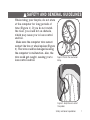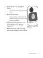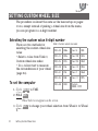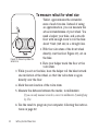
1
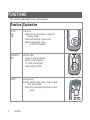
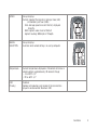
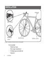
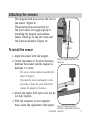
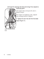
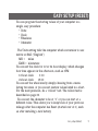
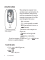
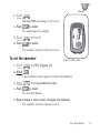
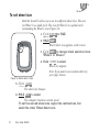
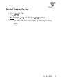
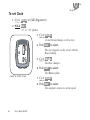
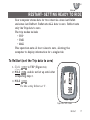
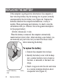
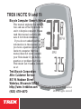
TREK INCITE 9i and 11i
Bicycle Computer Owner’s Manual
This manual explains the installation and use of the Trek Incite 9i
and 11i bicycle computer. Please
read this manual carefully and
save it for future reference. F
MPH
If you do not understand the
information in this manual, or
you have a question about your
Incite 9i computer that this
CLK TME AVG MAXTRP AVG
manual does not cover, consult
your Trek dealer. If you have a
question or problem that your
Trek dealer can’t handle, contact
us at:
Trek Bicycle Corporation
Attn: Customer Service
801 W. Madison Street
Waterloo, Wisconsin 53594
http://www. trekbikes.com
(920) 478-4670
© Copyright Trek Bicycle Corporation
2006 All rights reserved
Contents
Safety and general guidelines...................................................1
Functions...................................................................................2
Installation.................................................................................4
Placing the computer on the handlebar...............................5
Placing the magnet...............................................................7
Attaching the computer wire................................................8
Attaching the sensors...........................................................9
Easy setup (ReSet)...................................................................11
ReStart- Getting ready to ride................................................17
Additional information............................................................18
Troubleshooting......................................................................19
Replacing the battery..............................................................20
Setting custom wheel size.......................................................22
Limited Warranty.....................................................................25
ii
Safety and general guidelines
While riding your bicycle, do not stare
at the computer for long periods of
time (Figure 1). If you do not watch
the road, you could hit an obstacle,
which may cause you to lose control
and fall.
Make sure the computer wire cannot
contact the tire or wheel spokes (Figure
2). The wire could be damaged causing
the computer to malfunction. Also, the
wire could get caught, causing you to
lose control and fall.
Figure 1- Watch the road when
riding.
Figure 2- Keep the wire out of
the spokes
Safety and General guidelines
Functions
Table 1- Function abbreviations, names, and explanations
Function Explanation
Clock
CLK
TME
Time of day
Displays in hours and minutes, or stopwatch
showing seconds.
12-hour with AM/PM or 24-hour format
Highest reading: 23:59 (clock)
or 23:59:59 (stopwatch)
Odometer
ODO
Distance ridden
Displays in miles or kilometers.
TRP-Trip (since last Restart)
TTL- Total since last Reset
Highest reading: 99,999
Pacer
CLK
CLK
TME
AVG
MAX
TRP
ODO
MH
Always displays
Indicates whether current speed is faster or slower
than average speed
Displayed by arrow pointing up (faster) or down
(slower).
CLK
TME
AVG
MAX
TRP
ODO
Functions
MH
Speed
Wheel
selection
Always displays
Current speed of the bicycle in miles per hour (MH)
or kilometers per hour (KMH)
AVG- Average speed since last Restart, displayed
to tenths.
MAX- Highest value since last Restart
Highest readings: 80.5mph or 129.6kph
CLK
TME
AVG
MAX
TRP
ODO
Always displays
Indicates which wheel setting is in use by computer
MH
CLK
TME
AVG
MAX
TRP
ODO
Temperature
Current temperature displayed in Fahrenheit or Celsius in
whole numbers, updated every 30 seconds. Range:
• -2 to 140°F +/-2°
• -19 to 60°C +/-1°
CAD
(11i only)
Cadence
Number of revolutions per minute of the crankset displayed in whole number. Maximum 240
MH
.
Functions
Installation
Stem mount
Handlebar
mount
Speed sensor
Figure 3- Location on bicycle of sensors and computer
Tools needed:
• Electrical tape
• Slot-type screwdriver
• Phillips-type screwdriver
• Scissors
Installation
Cadence sensor
Placing the computer on the handlebar
The Trek Incite 9i or 11i computer can be
mounted on the handlebar or on the stem
(Figure 3).
To install the computer on handlebar
1. Select the bar clamp that fits your bike.
31.8mm bars: large clamp
25.4mm and 26.0mm: small clamp
22.2mm bar: small clamp with rubber shim
2. Insert the handlebar clamp into the back
of the computer base (Figure 4) and slide
it towards the front of the base.
Figure 4- Clamp and friction pad
in computer base
3. Insert the rubber friction pad into the computer base, aligned
across the computer base.
4. With the wire pointing toward the front of the bike, wrap the bar
clamp around the handlebar.
5. Insert the screw through the washer and into the computer base.
6. Tighten the screw until the computer base cannot rotate on the
handlebar.
7. Slide the computer into the computer base until the front of the
computer and computer base line up.
Installation
Check that the computer base cannot
be rotated around the handlebar,
and that the computer cannot slide
backwards on the computer base
(Figure 5).
To install the computer on the stem
1. Insert the rubber friction pad into
the computer base, aligned along the
computer base.
Figure 5- Make sure the computer cannot be bounced off.
2. Insert two nylon ties through the
computer base (Figure 6).
3. Place the base on the stem and tighten the
nylon tie.
4. Slide the computer into the computer
base until the front of the computer and
computer base line up.
5. Check that the computer base cannot be
rotated around the stem and the computer
cannot slide backwards on the computer
base.
Figure 6- Nylon tie threaded
through computer base
Installation
6. Tighten the nylon ties and trim the excess
length.
Placing the magnet
The wheel magnet must be aligned so that it passes across the
sensor. As the magnet passes the sensor, it must be no further
from the sensor than 1 to 3mm (1/32 to 1/8 inch).
The wheel magnet has a ‘T’ shaped slot with two configurations: round spokes and flat or bladed spokes (Figure 7).
To install the wheel magnet
1. Remove the screw from the magnet.
2. Slide the slot in the back of the magnet
over the spoke.
For a flat or bladed spoke, start the
spoke near the end where the spoke is
round, and align the top of the ‘T’ with
the spoke as you slide the magnet up the
blade (Figure 7).
3. Thread the screw into the magnet until it
is snug against the spoke.
Figure 7- Installing magnet on
round or oval spokes
Installation
Attaching the computer wire
The computer wire is usually longer than needed. Extra wire
length can be diverted by wrapping it around the brake housing
prior to routing it down the fork blade or down tube (Figure 8).
Make sure the computer wire is not pulled tight when the
handlebar is turned all the way to either side.
To attach the computer wire
1. Determine the length of wire to divert by
holding the sensor at its desired mounting
point.
2. Wrap the wire around the front brake
cable, diverting the determined amount.
Figure 8- Trim excess nylon tie
length
Installation
3. Continue routing the wire, either by
wrapping around the fork or frame tube,
or attach the wire to the fork or frame
tube with electrical tape.
4. As needed, solidify the wire attachment
with either nylon ties or electrical tape.
Attaching the sensors
The magnet must pass across the line on
the sensor (Figure 9).
These instructions are written for
the front wheel, but apply equally to
installing the magnet and cadence
sensor which go on the left crank and
the frame’s chainstay (Figure 10).
To install the sensor
1.0 3.0mm
1. Align the sensor with the magnet.
2. Orient the sensor so that the clearance
between the sensor and the magnet is
between 1 to 3mm.
The sensor can be rotated around the fork
about 45 degrees.
If needed, the sensor and magnet can be
moved up or down the spoke and fork to
change the amount of clearance.
Figure 9- Magnet alignment and
clearance
3. Attach the sensor with nylon ties, but do
not fully tighten.
4. With the computer in the computer
base, check the alignment of the sensor
Figure 10- Magnet placed on
crankarm, aligned with sensor on
Installation chainstay
and magnet by spinning the wheel and noting if the computer is
displaying speed.
If the computer shows current speed, the sensor is
reading the magnet.
If the computer is not displaying a value, realign the
sensor and magnet until one is displayed.
5. Tighten the nylon ties and trim the excess
length (Figure 11).
Figure 11- Trim excess nylon tie
length
10
Installation
Easy setup (ReSet)
You can program the starting values of your computer in a
single, easy procedure:
• Units
• Clock
• Wheelsize
• Odometer
The Units setting tells the computer which conversion to use:
metric or SAE (“English”):
MH = miles
KMH = kilometers
You can set the clock for 12 or 24 hour display, which changes
how time appears in the afternoon, such as 3PM:
12 hour clock
3:00
24 hour clock
15:00
You can set the wheel size by simply choosing from a menu
listing tire sizes, or you can set custom values listed in a chart.
For the most precision, do a “rollout” test. The rollout test is
described on page 22.
You can set the odometer to be at “0” or you can start at a
different value. This allows you to keep track of your previous
mileage after the computer has Reset (started over at 0), such
as after installing a new battery.
Easy setup (ReSet)
11
Using the buttons
When setting the computer, there
are three ways to use the buttons. To
help you remember, notice the way
MPH
each term is underlined. To help you
remember, these terms will look the
Set
same throughout the manual.
Push- touch once
Cycle - push repeatedly as needed
Hold- push and hold in for two or
three seconds
Mode
The buttons on the computer are
Figure 12- Buttons on the Incite
9i and 11i computer
(Figure 12):
Set• button on the right side
Mode button on the bottom
To set the computer, you must Push, Cycle, or Hold the two
buttons in a specific sequence.
F
CLK TME AVG MAXTRP AVG
To set the units
1. Cycle Mode to MAX (Figure 12).
2. Hold Set•
KMH or MH flashes.
12
Easy setup (ReSet)
CLK
TME
AVG
MAX
TRP
ODO
MH
Set
Mode
3. Cycle Mode
MH and KMH interchange on the screen.
4. Push Set• to select.
The temperature icon display.
F
5. Cycle Mode to C or F
MPH
CLK TME ODO MAXTRP AVG
6. Push Set• to select.
The computer returns to the start screen.
To set the odometer
Figure 13- ODO screen
1. Cycle Mode to ODO (Figure 13).
2. Hold Set•
5-digit odometer value appears with first digit flashing.
3. Cycle Mode to your preferred value.
4. Push Set• to select.
The next digit flashes.
5. Repeat steps 3 and 4 until all digits are selected.
The computer returns to the start screen.
Easy setup (ReSet)
13
CLK
TME
AVG
MAX
TRP
ODO
MH
Set
Mode
To set wheel size
Both the 9i and 11i allow you to use two different wheel sizes. The icon
for Wheel 1 is a small circle. The icon for Wheel 2 is a partial circle
surrounding the Wheel 1 icon (Figure 14).
1. Cycle Mode to TME.
2. Hold Set•
Wheel Select icon appears on the screen.
3. Cycle Set• to change wheel selection from
Wheel 1 to Wheel 2.
Figure 14- Wheel select screen
4. Push Mode to select.
Wheel size appears.
Note: If you want to set a custom wheel size,
go to page 24 now.
5. Cycle Mode
The wheel size changes.
6. Hold Set• to select.
The computer returns to current speed.
To set the second wheel size, repeat the instructions, but
select the other Wheel Select icon.
14
Easy setup (ReSet)
CLK
TME
AVG
MAX
TRP
ODO
To select the wheel for use
MH
Set
Mode
1. Cycle Mode to TRP
2. Hold the left Mode and the right Mode together.
The Wheel Select icon changes (Figure 14). Repeat step 2 to change
again.
Easy setup (ReSet)
15
CLK
TME
AVG
MAX
TRP
ODO
MH
Mode
To set Clock
1. Cycle Mode to CLK (Figure 15).
2. Hold Set•
“12” or “24” flashes.
3. Cycle Mode
12 and 24 interchange on the screen.
F
MPH
CLK TME AVG MAX TRP AVG
Figure 15- CLOCK screen
4. Push Set• to select
The clock appears on the screen with the
Hour flashing.
5. Cycle Mode
The Hour changes.
6. Push Set• to select.
The Minutes flash.
7. Cycle Mode
8. Push Set• to select.
The computer returns to current speed.
16
Easy setup (ReSet)
Set
CLK
TME
AVG
MAX
TRP
ODO
MH
Set
Mode
ReStart- Getting ready to ride
Your computer stores data for two intervals- since last ReSet
and since last ReStart. ReSet sets ALL data to zero. ReStart sets
only the Trip data to zero.
The trip modes include
• TRP
• TME
• MAX
This operation sets all four values to zero, allowing the
computer to display information for a single ride.
To ReStart (set the Trip data to zero)
1. Cycle Mode to TRP (Figure 16).
2. Hold Set•, and do not let up until after
completing step 3.
3. Hold Mode.
The Max setting ReStarts at ‘0’.
F
MPH
CLK TME AVG MAX TRP AVG
Figure 16- TRP screen
ReStart
17
CLK
TME
AVG
MAX
TRP
ODO
Additional information
MH
Mode
Changing mode
Once the computer is programmed and installed, it is very easy
to use. To change to different modes (functions), simply Cycle
the Mode button until the desired function appears, shown by
the spelled name of the function.
Removing the computer from the computer base
The computer is held on its base by a flexible snap. To remove
the computer, press firmly on the computer (not on the base) in
a rearward direction.
Using the computer in wet weather
Bicycle computers function on electricity. If the electrical
contacts between the computer and its base become saturated,
the electrical signals may become irregular or interrupted
entirely. If the computer is to be used in heavy rain, etc., we
recommend that a plastic bag be put over the computer and its
base. The other parts of the computer system are waterproof.
18
Additional Information
Set
Troubleshooting
The Incite 9i computer is designed to be easy to install and
maintain. However, computers occasionally have problems.
Table 3 shows some possible problems, causes, and solutions:
Table 3- Common problems and solutions
Blank screen
Computer is in shipping mode. Push a button.
Battery is dead, or installed incorrectly. Reinstall good battery.
Erratic data
Magnet misaligned or too far away. Re-adjust magnet and sensor placement.
Battery power is low. Replace battery.
No current speed
Magnet misaligned or too far away. Re-adjust magnet and sensor placement.
Speed is incorrect.
Wheel size is incorrect. Reset computer.
Sensor is not reading magnet properly. Readjust magnet and sensor alignment.
Troubleshooting
19
Replacing the battery
If the computer is giving erratic information, the computer or
hear rate strap battery may be running low on power (normally
accompanied by the low battery icon, Figure 16). Replace the
batteries whenever the computer malfunctions, or every 6
months. When purchasing new batteries, it is best to take the
old batteries with you. However, this is the generic description
for the proper battery:
CR2032, lithium cell, 3 volts
When the battery is removed, the computer automatically
resets function totals to Zero. After installing a new battery, you
can manually set your totals, but you must note those values
before removing the battery.
To replace the battery
1. Remove the computer from its base.
2. Identify the battery cover, with its deep
slot (a similar battery cover is found on
the back, or skin-side, or the heart rate
strap).
Figure 17- Removing
cover
20
Replacing the Battery
battery
3. Insert a large coin into the slot and rotate
in a counter-clockwise direction about
one-quarter turn (Figure 17).
4. Lift the battery cover, exposing the
battery.
Be careful to avoid losing the rubber O-ring
seal.
5. Remove the old battery.
It may be possible to shake the battery out.
Otherwise, carefully pry the battery up with
a thin tool or knife blade.
6. Insert the new battery with the ‘cross’
and identifying label pointing up
(Figure 18).
7. Replace the battery cover (and O-ring
seal) and turn one-quarter turn clockwise.
Figure 18- The ‘cross’ on the battery points up
Replacing the Battery
21
CLK
TME
AVG
MAX
TRP
ODO
MH
Set
Mode
Setting custom wheel size
The procedure is almost the same as the basic setup on pages
13-14, except instead of picking a wheel size from the menu,
you can program in a 4-digit number.
Selecting the custom value 4-digit number
There are two methods for
selecting the custom wheel size
value:
• Select a value from Table 3,
Custom wheel size codes
• Do a rollout test to measure
the circumference of your wheel
(page 24).
To set the computer
Table 3- Custom wheel size codes
700 x 20
2086
26 x 1.5
2010
700 x 23
2096
26 x 1.90
2045
700 x 25
2105
26 x 1.95
2050
700 x 28
2136
26 x 2.0
2055
700 x 32
2155
26 x 2.1
2068
700 x 35
2168
26 x 2.2
2075
700 x 38
2180
Custom
0000 - 2999
1. Cycle Mode to TME.
2. Hold Set•
Wheel Select icon appears on the screen.
3. Cycle Set• to change your wheel selection from Wheel 1 to Wheel
2.
22
Setting Custom Wheel Size
CLK
TME
AVG
MAX
TRP
ODO
MH
Set
Mode
4. Push Mode to select.
Wheel size appears.
Note: If you want to set a custom wheel size, go to page 24 now.
5. Cycle Mode through the wheel sizes tro the 4-digit number.
6. Push Set•
The left-hand digit flashes.
7. Cycle Mode to the desired value.
8. Push Set• to select.
The next digit flashes.
9. Repeat steps 7 and 8 to select all four digits.
10. Hold Set•
The computer returns to current speed.
Setting Custom Wheel Size
23
To measure rollout for wheel size
Table 1 approximates the circumference of each tire size. Instead of using
an approximation, you can measure the
actual circumference of your wheel. You
need a helper, your bike, and a smooth
floor with enough room to roll the bike
about 7 feet (245 cm) in a straight line.
Figure 19- Measuring rollout for
wheel size
1. With the valve stem of the front wheel
directly over the floor Figure 19), sit on
the bike.
2. Have your helper mark the floor at the
valve stem.
3. While you sit on the bike, have the helper roll the bike forward
one revolution of the wheel, so that the valve stem is again
directly over the floor.
4. Mark the new location of the valve stem.
5. Measure the distance between the marks, in millimeters.
If you can only measure in inches, convert to millimeters by multiplying
by 25.4.
6. Use the result to program your computer, following the instructions on page 22.
24
Setting Custom Wheel Size
Limited Warranty
Trek Bicycle Corporation warrants each new Incite computer
against defects in workmanship and materials.
This warranty covers
Trek Incite computer models 6i, 8i, 9i, 11i, ACH, and ACH Digital
for a period of two years from the date of sale.
This warranty does not cover
• Normal wear and tear, including the length of battery life
• Improper assembly
• Installation of parts or accessories not originally intended
for, or compatible with the component as sold
• Damage or failure due to accident, misuse, abuse, or neglect
This warranty is void in its entirety by any modification of the
component or its parts.
This warranty is expressly limited to the repair or replacement of a
defective item and is the sole remedy of the warranty. This warranty
extends from the date of purchase, applies only to the original owner, and
is not transferable. Trek is not responsible for incidental or consequential damages. Some states do not allow the exclusion of incidental or
consequential damages, so the above exclusion may not apply to you.
Claims under this warranty must be made through an authorized dealer.
Proof of purchase is required.
This warranty gives the consumer specific legal rights, and those rights
may vary from place to place. This warranty does not affect the statutory
rights of the consumer.
Limited Warranty
25