1
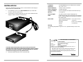
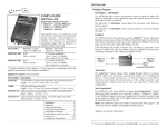
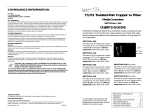
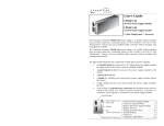
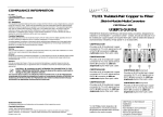
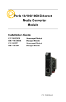
COMPLIANCE INFORMATION
UL Listed
C-UL Listed (Canada)
CISPR/EN55022 Class A
48 VDC-to-12 VDC
FCC Regulations
External Power Supply
This equipment has been tested and found to comply with the limits for a class A digital device, pursuant
to part 15 of the FCC rules. These limits are designed to provide reasonable protection against harmful
interference when the equipment is operated in a commercial environment. This equipment generates,
uses, and can radiate radio frequency energy and, if not installed and used in accordance with the
instruction manual, may cause harmful interference to radio communications. Operation of this
equipment in a residential area is likely to cause harmful interference, in which case the user will be
required to correct the interference at the user’s own expense.
Canadian Regulations
This digital apparatus does not exceed the Class A limits for radio noise for digital apparatus set out on
the radio interference regulations of the Canadian Department of Communications.
Le présent appareil numérique n'émet pas de bruits radioélectriques dépassant les limites applicables
aux appareils numériques de la class A prescrites dans le Règlement sur le brouillage radioélectrique
édicté par le ministère des Communications du Canada.
SPS-48V
USER’S GUIDE
The TRANSITION Networks SPS-48V 48-to-12 VDC External Power Supply
provides isolated 12 VDC output voltage from a 48 VDC external input voltage
source to a media converter or similar devce.
European Regulations
Warning
This is a Class A product. In a domestic environment this product may cause radio interference in which
case the user may be required to take adequate measures.
Achtung !
Dieses ist ein Gerät der Funkstörgrenzwertklasse A. In Wohnbereichen können bei Betrieb dieses Gerätes
Rundfunkstörungen auftreten, in weichen Fällen der Benutzer für entsprechende Gegenmaßnahmen
werantwortlich ist.
Attention !
Ceci est un produit de Classe A. Dans un environment domestique, ce produit risque de créer des
interférences radioélectriques, il appartiendra alors à l’utilsateur de prende les measures spécifiques
appropriées.
Trademark Notice
All registered trademarks and trademarks are the property of their respective owners.
Copyright Restrictions
© 2001 TRANSITION Networks.
All rights reserved. No part of this work may be reproduced or used in any form or by any means –
graphic, electronic, or mechanical – without written permission from TRANSITION Networks.
Printed in the U.S.A.
33212.A
Installation .................................2
Maintenance ..............................4
Technical Specifications .............6
Compliance Information.............8
INSTALLATION
NOTE: The TRANSITION Networks 48-to-12 VDC External Power Supply is
shipped with four (4) attached feet.
Compliance
UL listed EN60950; FCC & CISPR class A; CE Mark
Dimensions
5.6" x 3.3"" x 1.6""
Power Distribution
+12VDC at 0.8 A maximum.
Power Consumption
14 watts maximum
1.
For installation, place on any well-ventilated table-top or shelf with
access to a 48 VDC power source.
Long Term Stability
0.1% for eight (8) hours (after 20 minutes warm-up)
Efficiency
70 % (typical)
2.
Connect barrel connector attached to 12 VDC cord on External Power
Supply to media converter or similar device
Noise and Ripple
1% peak-to-peak of output voltage (typical)
MTBF
Greater than 60,000 hours with typical load operating
at 20°C ambient temperature (calculated according to
MIL-HDBK-217E)
Environment
Typical Operating Temperature*: 0-50°C (32° to 122° F )
Storage Temperature:
Warranty
-20 to 85°C
Humidity:
10-90%, non condensing
Altitude:
0-10,000 feet
Lifetime
DECLARATION OF CONFORMITY
RXC
PWR
LKF
RXF
LKC
*At operating temperature range 50°C-70°C, operates linearly to 50% of full
rating.
Name of Mfg:
CAUTION: Ensure that 48 VDC power source is NOT powered when
connecting power to the 48-to-12 External Power Supply. Failure to observe
this caution could result in damage to, and subsequent failure of, the 48-to12 External Power Supply and of any attached device.
3.
Transition Networks
6475 City West Parkway, Minneapolis MN 55344 USA
Model:
SPS-48V External Power Supply
Part Number:
SPS-48V
Regulation:
EMC Directive 89/336/EEC
Purpose: To declare that the SPS-48V to which this declaration refers is in
conformity with the following standards.
EMC-CISPR 22: 1985 Class A; EN 55022: 1988 Class A; EN 50082-1:1992;
EN 60950 A4:1997; IEC 801.2, IEC 801.3, and IEC 801.4; IEC 950
I, the undersigned, hereby declare that the equipment specified above conforms to the
above Directive(s) and Standard(s).
Ensure that external power source is powered OFF.
_May 8, 2001_____
Stephen Anderson, Vice-President of Engineering
Date
TECHNICAL SPECIFICATIONS
4.
Connect +48-VDC terminal to 48-to-12 VDC External Power Supply
terminal block control marked “+”. Turn terminal screw clockwise to
secure.
5.
Connect -48-VDC terminal to 48-to-12 VDC External Power Supply
terminal block control marked “-”. Turn terminal screw clockwise to
secure.
6.
Connect ground terminal to 48-to-12 VDC External Power Supply
terminal block control marked “chassis ground”. Turn terminal screw
clockwise to secure.
Input
Input Voltage
48 VDC
Inrush Current
0.20 A (peak cold start)
Hold-Up Time
20 msec minimum at full load and nominal input
voltage
Isolation Voltage
(Dielectric withstand) Meets IEC 960 for one minute.
1,500 VAC:
Output/Input
500 VAC:
Input/Safety GND
500 VAC:
Output/Safety GND
Output
Output Voltage
12 VDC
Output Current
0.8 A
Line Regulation
±0.5 % of all output within specified range
Load Regulation
±1.0 % at 20 % load to full-rated load
Cross Regulation
±1.0 % maximum on any output change from 50 % to
100 % rated load
Transient Response
Output voltage returns in less than 3 msec following a
50 % load change
Over Load Protection
(OLP) When the average power rating exceeds 125%150% of maximum power, output voltages reduced to
a safe dissipation level; protects against short circuit of
any output.
-
+
GND
Over Voltage Protection (OVP) 124 % ±8 % on output.
Over Circuit Protection Withstands a continous short without damage; returns
automatically to regulation upon removal of short.
No Load Operation
No damage to power supply when operating at no
load.
Overshoot Protection
No voltage spike at power-on, power-off, or power
failure.
7.
Ensure that external power source is powered ON.
MAINTENANCE
Replacing Power Supply Module Fuse
6.
Carefully lift cover from External Power Supply.
7.
Locate fuse on 48-VDC Power Supply Module.
CAUTION: Wear a grounding device and observe electrostatic discharge
precautions when replacing the fuse in the 48-to-12 VDC External Power
Supply. Failure to observe this caution could result in damage to, and
subsequent failure of, the 48-to-12 VDC External Power Supply.
CAUTION: Replace fuse only with same size and rating. Failure to observe this
caution could result in equipment damage.
CAUTION: Ensure that power source is NOT powered when disconnecting
power from, or connecting power to, the 48-to-12 External Power Supply.
Failure to observe this caution could result in damage to, and subsequent
failure of, the 48-to-12 External Power Supply and of any attached device.
1.
Ensure that external power source is powered OFF.
2.
Disconnect +48-VDC terminal from Media Conversion Center terminal
block control marked “+” by turning terminal screw counter-clockwise.
3.
Disconnect -48-VDC terminal from Media Conversion Center terminal
block control marked “-” by turning terminal screw counter-clockwise.
4.
Disconnect ground terminal from Media Conversion Center terminal
block control marked “chassis ground” by turning terminal screw
counter-clockwise.
5.
Remove and retain four (4) screws that secure cover to External Power
Supply.
Fuse Holder
Fuse
8.
Carefully remove fuse from fuse holder.
9.
Install same size and rating replacement fuse in fuse holder.
10.
Carefully slide cover onto External Power Supply.
11.
Replace four (4) retained screws that secure cover to External Power
Supply.
12.
Connect +48-VDC terminal to 48-to-12 VDC External Power Supply
terminal block control marked “+”. Turn terminal screw clockwise to
secure.
13.
Connect -48-VDC terminal to 48-to-12 VDC External Power Supply
terminal block control marked “-”. Turn terminal screw clockwise to
secure.
14.
Connect ground terminal to 48-to-12 VDC External Power Supply
terminal block control marked “chassis ground”. Turn terminal screw
clockwise to secure.
15.
Ensure that external power source is powered ON.