1
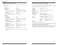
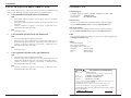
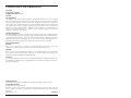
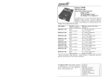
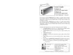
USER’S GUIDE
F-SM-MM-06
Stand-Alone Media Converter
• OC-12 ATM / SONET
• Singlemode to Multimode
Transition Networks F-SM-MM-06
Ethernet Media Converter extends ATM or
SONET over singlemode fiber-optic cable
up to 40 km.
Part Number
Port One - Fiber-Optic
F-SM-MM-06
SC, 1300 nm multimode SC, 1310 nm singlemode
2 km (1.2 miles)*
15 km (9.3 miles)*
Port Two - Fiber-Optic
F-SM-MM-06(XL)
SC, 1300 nm multimode SC ,1310 nm singlemode
2 km (1.2 miles)*
40 km (24.9 miles)*
* Typical maximum cable distance. Actual distance is dependent upon the
physical characteristics of the network. See the Cable Specifications on page 4
for more information on the cable length.
Optional Accessories (sold separately)
Part Number Description
SPS-1872-SA Optional External Power Supply; 18-72VDC Stand-Alone
Output: 12.6VDC, 1.0 A
SPS-1872-CC Optional External Power Supply; 18-72VDC Piggy-back;
Output: 12.6VDC, 1.0 A
E-MCR-03
12-Slot Media Converter Rack (includes universal internal power
supply) 17 x 15 x 5 in. (432 x 381 x 127 mm)
WMBL
Optional Wall Mount Brackets
Length: 4.0 in. (102 mm), Fits converter length: 4.7 in. (119 mm)
WMBV
Optional Vertical Mount Bracket; Length: 5.0 in. (127 mm)
WMBD
Optional DIN Rail Mount Bracket; Length: 5.0 in. (127 mm)
WMBD-F
Optional DIN Rail Mount Bracket (flat); Length: 3.3in. (84 mm)
Installation . . . . . . . . . . . . . . . . . .2
Operation . . . . . . . . . . . . . . . . . . .3
Cable Specifications . . . . . . . . . . .4
Technical Specifications . . . . . . . .5
Fault Isolation and Correction . . .6
Contact Us . . . . . . . . . . . . . . . . . .7
Compliance Information . . . . . . . .8
F-SM-MM-06
INSTALLATION
OPERATION
Installing the Cable
Using Status LEDs
FIBER
Use the status LEDs to monitor the Media Converter operation in the network.
1.
Locate or build fiber cable with male, two-stranded TX to RX connectors
installed at both ends.
Pwr
Steady LED indicates connection to external AC and DC power.
Link (left)
Steady LED indicates multimode fiber link connection.
Connect the fiber cables to the Media Converter as described:
• Connect the male TX cable connector the female TX port.
• Connect the male RX cable connector to the female RX port.
Link (right)
Steady LED indicates singlemode fiber link connection.
2.
3.
(TX)
Connect the fiber cables to the other device (another media converter,
hub, etc.) as described:
• Connect the male TX cable connector the female RX port.
• Connect the male RX cable connector to the female TX port.
Connect the fiber cable
to the Media Converter
as shown.
(RX)
(TX)
(RX)
PWR
Multimode
Link
Singlemode
Connect the fiber cable
to the other device
(media converter,
hub, etc.) as shown
RX
RX
TX
TX
Power the Media Converter
AC
1.
Install the power adapter cord to the back of the Media Converter.
2.
Connect the power adapter plug to AC power.
3.
Verify that the Media Converter is powered by observing the illuminated
LED power indicator light.
DC
Consult the User’s Guide for the Transition Networks SPS1872-xx DC External
Power Suppy for powering the Media Converter.
2
Tech Support: 800-260-1312 International: 952-941-7600 7am-6pm CST (GMT-6:00)
[email protected] -- Select the “Transition Now” Link for a Live Web Chat
3
F-SM-MM-06
CABLE SPECIFICATIONS
TECHNICAL SPECIFICATIONS
The physical characteristics must meet or exceed ANSI TI.646-1995, ITU G.957
specifications.
Bit Error Rate:
Multimode
For use with Transition Networks Model F-SM-MM-06 or equivalent
<10-10
Product is certified by the manufacturer to comply with DHHS Rule 21/CFR,
Subchapter J applicable at the date of manufacture.
1300 nm
Standards:
ANSI TI.646-1995, ITU G.957
Recommended:
Optional:
62.5/125 µm
100/140, 85/125, 50/125 µm
Data Rate:
622 Mb/s
Case Dimensions:
4.7" x 3.0" x 1.0" (119 mm x 76 mm x 25 mm)
Fiber Optic Transmitter Power:
Fiber Optic Receiver Sensitivity:
Link Budget:
Minimum cable distance*
Typical maximum cable distance*
min: -19.0 dBm
min: -26.0 dBm
7.0 dB
2 meters (6.6 ft)
2 km (1.2 miles)
Weight:
10 oz. (283 g) (approximate)
Power Consumption:
3.1 W
Power Supply
DC Output:
12VDC, 0.4 A (minimum)
minimum output regulation: 5%
Connector: 2.1mm barrel, center pin positive
MTBF
51,185 hours (MIL217F2 V5.0) (MIL-HDBK-217F)
124,339 hours (Bellcore7 V5.0)
max: -14.0 dBm
max: -14.0 dBm
Singlemode
Recommended:
9 µm
F-SM-MM-06
Fiber Optic Transmitter Power:
Fiber Optic Receiver Sensitivity:
Link Budget:
Minimum cable distance*
Typical maximum cable distance*
1310 nm
min: -15.0 dBm max: -8.0 dBm
min: -28.0 dBm max: -7.0 dBm
13.0 dB
2 meters (6.6 ft)
15 km (9.3 miles)
Environment:
Tmra*:
Storage Temp:
Humidity:
Altitude:
Warranty:
Lifetime
F-SM-MM-06(XL)
Fiber Optic Transmitter Power:
Fiber Optic Receiver Sensitivity:
Link Budget:
Minimum cable distance*
Typical maximum cable distance*
1310 nm
min: -3.0 dBm
max: +2.0 dBm
min: -29.0 dBm max: -7.0 dBm
26.0 dB
2 meters (6.6 ft)
40 km (24.9 miles)
CAUTION: Visible and Invisible Laser Radiation When Open. Do Not Stare
Into Beam Or View Directly With Optical Instruments.
0 to 50°C (32 to 122°F)
-20 to 85°C (-4 to 185°F)
10 to 90%, non condensing
0 to 10,000 feet
*Manufacturer’s rated ambient temperature.
CAUTION: Use of controls, adjustments or the performance of procedures
other than those specified herein may result in hazardous radiation exposure.
* Actual distance is dependent upon the characteristics of the network
installation.
4
Tech Support: 800-260-1312 International: 952-941-7600 7am-6pm CST (GMT-6:00)
[email protected] -- Select the “Transition Now” Link for a Live Web Chat
5
F-SM-MM-06
FAULT ISOLATION and CORRECTION
If the Media Converter fails, isolate and correct the failure by determining the
answers to the following questions and then taking the indicated action:
1.
Is the PWR LED on the Media Converter illuminated?
NO
•
•
•
Is the power adapter the proper type of voltage and cycle frequency
for the AC outlet?
Is the power adapter properly installed in the Media Converter and in
the outlet?
Contact Technical Support: US/Canada: 1-800-260-1312,
International: 00-1-952-941-7600.
YES
•
2.
Proceed to step 2.
Is the multimode Link LED (on the left) illuminated?
NO
•
•
•
Check the fiber cables for proper connection.
Verify that the TX and RX cables on the Media Converter are
connected to the RX and TX ports, respectively, on the other device.
Contact Technical Support: US/Canada: 1-800-260-1312,
International: 00-1-952-941-7600.
YES
•
3.
Proceed to step 3.
Is the singlemode Link LED (on the right) illuminated?
CONTACT US
Technical Support
Technical support is avialable 7:00 AM - 6:00 PM CST (GMT -6:00)
US and Canada:
1-800-260-1312
International:
00-1-952-941-7600
Transition Now
Chat live via the Web with Transition Networks Technical Support.
Log onto www.transition.com and click the Transition Now link.
Web-Based Seminars
Transition Networks provides seminars via live web-based training.
Log onto www.transition.com and click the Learning Center link.
E-Mail
Ask a question anytime by sending an e-mail to our technical support staff.
[email protected]
Address
Transition Networks
6475 City West Parkway
Minneapolis, MN 55344, USA
telephone:
952-941-7600
toll free:
800-526-9267
fax:
952-941-2322
NO
•
•
•
Check the fiber cables for proper connection.
Verify that the TX and RX cables on the Media Converter are
connected to the RX and TX ports, respectively, on the other device.
Contact Technical Support: US/Canada: 1-800-260-1312,
International: 00-1-952-941-7600.
YES
•
Contact Technical Support: US/Canada: 1-800-260-1312,
International: 00-1-952-941-7600.
DECLARATION OF CONFORMITY
Name of Mfg:
Transition Networks
6475 City West Parkway, Minneapolis MN 55344 USA
Model:
F-SM-MM-06 Series Media Converters
Part Number(s):
F-SM-MM-06, F-SM-MM-06(XL)
Regulation:
EMC Directive 89/336/EEC
Purpose: To declare that the F-SM-MM-06 to which this declaration refers is in
conformity with the following standards.
EMC-CISPR 22: 1985 Class A; EN 55022: 1988 Class A; EN 50082-1:1992;
EN 60950 A4:1997; IEC 801.2, 801.3, 801.4; IEC 950; 21 CFR subpart J
I, the undersigned, hereby declare that the equipment specified above conforms to the above
Directive(s) and Standard(s).
January 1, 1997
Stephen Anderson, Vice-President of Engineering
6
Tech Support: 800-260-1312 International: 952-941-7600 7am-6pm CST (GMT-6:00)
Date
[email protected] -- Select the “Transition Now” Link for a Live Web Chat
7
COMPLIANCE INFORMATION
UL Listed
C-UL Listed (Canada)
CISPR22/EN55022 Class A
CE Mark
FCC Regulations
This equipment has been tested and found to comply with the limits for a class A digital
device, pursuant to part 15 of the FCC rules. These limits are designed to provide reasonable
protection against harmful interference when the equipment is operated in a commercial
environment. This equipment generates, uses, and can radiate radio frequency energy and, if
not installed and used in accordance with the instruction manual, may cause harmful
interference to radio communications. Operation of this equipment in a residential area is
likely to cause harmful interference, in which case the user will be required to correct the
interference at the user's own expense.
Canadian Regulations
This digital apparatus does not exceed the Class A limits for radio noise for digital apparatus
set out on the radio interference regulations of the Canadian Department of Communications.
Le présent appareil numérique n'émet pas de bruits radioélectriques dépassant les limites
applicables aux appareils numériques de la class A prescrites dans le Règlement sur le
brouillage radioélectrique édicté par le ministère des Communications du Canada.
European Regulations
Warning
This is a Class A product. In a domestic environment this product may cause radio
interference in which case the user may be required to take adequate measures.
Achtung !
Dieses ist ein Gerät der Funkstörgrenzwertklasse A. In Wohnbereichen können bei Betrieb
dieses Gerätes Rundfunkstörungen auftreten, in weichen Fällen der Benutzer für
entsprechende Gegenmaßnahmen werantwortlich ist.
Attention !
Ceci est un produit de Classe A. Dans un environment domestique, ce produit risque de créer
des interférences radioélectriques, il appartiendra alors à l'utilsateur de prende les measures
spécifiques appropriées.
Trademark Notice
All trademarks and registered trademarks are the property of their respective owners.
Copyright Restrictions
© 1997 - 2003 Transition Networks.
All rights reserved. No part of this work may be reproduced or used in any form or by any
means - graphic, electronic, or mechanical - without written permission from Transition
Networks.
Printed in the U.S.A.
33055.C