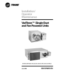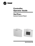
1
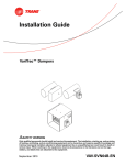
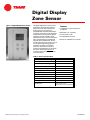
Digital Display Zone Sensor Figure 1: Digital Display Zone Sensor The digital display zone sensor has the functionality of the full-featured Trane DDC zone sensor with a liquid crystal display (LCD). The zone sensor is compatible withTrane VAV and VariTrac® controllers.The display can be toggled in the field from zone temperature to zone setpoint and can be viewed in either Fahrenheit or Celsius. A communications jack is provided forTrane portable edit terminal devices. Additionally, the On/ Cancel buttons allow the system to run in the occupied mode during nighttime operation. The ability to override to maximum and minimum airflow or position for field balancing is included in the sensor. Please visit trane.com or contact a localTrane representative for more information. Features LCD Readout of Zone Temperature or Setpoint Selectable °F or °C Display Communication Jack Occupied Mode Override Maximum and Minimum Override Table 1: Sensor Specifications ©2002 American Standard, Inc. All rights reserved Thermistor Resistance Rating 10k OHM at 77°F (25°C) Accuracy at 77°F (25°C) 0.4°F (0.2°C) Setpoint Resistance Rating 500 Ohms at 70°F (21.2°C) Display Zone Temperature Range 40 to 99°F (10 to 35°C) Display Setpoint Range 50 to 90°F (10 to 32°C) Operating Temperature 0 to 120°F (-18 to 49°C) Storage Temperature -20 to 130°F (-29 to 54°C) Humidity Range 5 to 95% non-condensing Power Supply 24 VAC Maximum VA load 4 VA Housing Material Rigid Vinyl Dimensions 4.5” x 2.8” x 1.1” (114 mm x 71 mm x 28 mm) VAV-SLB007-EN Table 2: Wiring Terminations at Sensor AVOID areas such as: Placement of the Sensor Behind doors Choose a mounting location on an interior wall near the return air grille, about five feet above the floor level, where air circulates freely and is of average temperature for the zone. On outside walls or walls facing uncontrolled areas In direct sunlight, or sources of radiant heat that could effect temperature measurement In line with discharge air from unit being controlled TB1-1 24 VAC Power Supply TB1-2 24 V Ground TB2-1 Zone Temperature TB2-2 Zone Sensor Ground TB2-3 Zone Setpoint TB3-1 Communication + TB3-2 Communication - Figure 2: Dimensional Data 2.8” (71 mm) ˚F ˚C MAX OVERRIDE UNNOCSETPOINT 3.3” (84 mm) 4.5” (114 mm) 2.1” ON (53 mm) CANCEL 1.1” (28 mm) Trane An American Standard Company www.trane.com For more information contact your local district office or e-mail us at comfort @trane.com Literature Order Number VAV-SLB007-EN File Number SB-TD-VAV-000-SLB007-EN-0602 Supersedes New Stocking Location La Crosse Trane has a policy of continuous product and product data improvement and reserves the right to change design and specifications without notice.