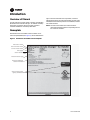
1
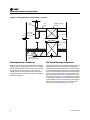
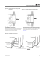
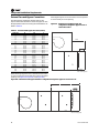
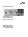
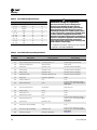
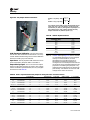
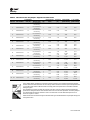
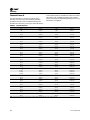
Installation, Operation
and Maintenance
Performance Climate Changer™ Air Handlers
Indoor and Outdoor Units
Sizes 3-120
SAFETY WARNING
Only qualified personnel should install and service the equipment. The installation, starting up, and
servicing of heating, ventilating, and air-conditioning equipment can be hazardous and requires specific
knowledge and training. Improperly installed, adjusted or altered equipment by an unqualified person could
result in death or serious injury. When working on the equipment, observe all precautions in the literature
and on the tags, stickers, and labels that are attached to the equipment.
October 2012
CLCH-SVX07C-EN
X-39641152010
Warnings, Cautions and Notices
Warnings, Cautions and Notices. Note that warnings,
cautions and notices appear at appropriate intervals
throughout this manual. Warnings are provide to alert
installing contractors to potential hazards that could result
in death or personal injury. Cautions are designed to alert
personnel to hazardous situations that could result in
personal injury, while notices indicate a situation that
could result in equipment or property-damage-only
accidents.
Your personal safety and the proper operation of this
machine depend upon the strict observance of these
precautions.
Read this manual thoroughly before operating or servicing
this unit.
ATTENTION: Warnings, Cautions and Notices appear at
appropriate sections throughout this literature. Read
these carefully:
Indicates a potentially hazardous
situation which, if not avoided, could
result in death or serious injury.
Indicates a potentially hazardous
CAUTIONs situation which, if not avoided, could
result in minor or moderate injury. It
could also be used to alert against
unsafe practices.
Indicates a situation that could result in
NOTICE: equipment or property-damage only
WARNING
must also be adhered to for responsible management of
refrigerants. Know the applicable laws and follow them.
WARNING
Proper Field Wiring and Grounding
Required!
All field wiring MUST be performed by qualified
personnel. Improperly installed and grounded field
wiring poses FIRE and ELECTROCUTION hazards. To
avoid these hazards, you MUST follow requirements for
field wiring installation and grounding as described in
NEC and your local/state electrical codes. Failure to
follow code could result in death or serious injury.
WARNING
Personal Protective Equipment (PPE)
Required!
Installing/servicing this unit could result in exposure to
electrical, mechanical and chemical hazards.
•
Before installing/servicing this unit, technicians
MUST put on all Personal Protective Equipment (PPE)
recommended for the work being undertaken.
ALWAYS refer to appropriate MSDS sheets and OSHA
guidelines for proper PPE.
•
When working with or around hazardous chemicals,
ALWAYS refer to the appropriate MSDS sheets and
OSHA guidelines for information on allowable
personal exposure levels, proper respiratory
protection and handling recommendations.
•
If there is a risk of arc or flash, technicians MUST put
on all Personal Protective Equipment (PPE) in
accordance with NFPA 70E or other country-specific
requirements for arc flash protection, PRIOR to
servicing the unit.
Important
Environmental Concerns!
Scientific research has shown that certain man-made
chemicals can affect the earth’s naturally occurring
stratospheric ozone layer when released to the
atmosphere. In particular, several of the identified
chemicals that may affect the ozone layer are refrigerants
that contain Chlorine, Fluorine and Carbon (CFCs) and
those containing Hydrogen, Chlorine, Fluorine and
Carbon (HCFCs). Not all refrigerants containing these
compounds have the same potential impact to the
environment. Trane advocates the responsible handling of
all refrigerants-including industry replacements for CFCs
such as HCFCs and HFCs.
Failure to follow recommendations could result in death
or serious injury.
Responsible Refrigerant Practices!
Trane believes that responsible refrigerant practices are
important to the environment, our customers, and the air
conditioning industry. All technicians who handle
refrigerants must be certified. The Federal Clean Air Act
(Section 608) sets forth the requirements for handling,
reclaiming, recovering and recycling of certain
refrigerants and the equipment that is used in these
service procedures. In addition, some states or
municipalities may have additional requirements that
© 2012 Trane All rights reserved
CLCH-SVX07C-EN
Warnings, Cautions and Notices
Ultraviolet (UV) Germicidal Irradiation Lights!
The United States Environmental Protection Agency (EPA)
believes that molds and bacteria inside buildings have the
potential to cause health problems in sensitive
individuals. If specified, Trane provides ultraviolet lights
(UV-C) as a factory-engineered and installed option in
select commercial air handling products for the purpose of
reducing microbiological growth (mold and bacteria)
within the equipment. When factory provided, polymer
materials that are susceptible to deterioration by the UV-C
light will be substituted or shielded from direct exposure
to the light. In addition, UV-C radiation can damage human
tissue, namely eyes and skin. To reduce the potential for
inadvertent exposure to the lights by operating and
maintenance personnel, electrical interlocks that
automatically disconnect power to the lights are provided
at all unit entry points to equipment where lights are
located.
WARNING
Equipment Damage From Ultraviolet (UV)
Lights!
Trane does not recommend field installation of
ultraviolet lights in its air handling equipment for the
intended purpose of improving indoor air quality. High
intensity C-band ultraviolet light is known to severely
damage polymer (plastic) materials and poses a
personal safety risk to anyone exposed to the light
without proper personal protective equipment (could
cause damage to eyes and skin). Polymer materials
commonly found in HVAC equipment that may be
susceptible include insulation on electrical wiring, fan
belts, thermal insulation, various fasteners and
bushings. Degradation of these materials can result in
serious damage to the equipment.
Trane accepts no responsibility for the performance or
operation of our air handling equipment in which
ultraviolet devices were installed outside of the Trane
factory.
CLCH-SVX07C-EN
3
Table of Contents
Warnings, Cautions and Notices . . . . . . . . . . 2
Outdoor Unit Weather Hoods . . . . . . . . . . .34
Introduction . . . . . . . . . . . . . . . . . . . . . . . . . . . . . 6
Overview of Manual . . . . . . . . . . . . . . . . . . . 6
Stacked Outdoor Units . . . . . . . . . . . . . . . . .34
Nameplate . . . . . . . . . . . . . . . . . . . . . . . . . . . . 6
Unit assembly . . . . . . . . . . . . . . . . . . . . . . .35
General Information . . . . . . . . . . . . . . . . . . . . . 7
Operating Environment . . . . . . . . . . . . . . . . 7
Vertical Seam Cap Installation . . . . . . . . .36
Unit Description . . . . . . . . . . . . . . . . . . . . . . . 7
Factory-Mounted Controls . . . . . . . . . . . . . 7
Pre-Packaged Solutions for Controls . . . . 7
Wiring . . . . . . . . . . . . . . . . . . . . . . . . . . . . . 8
Pre-Installation Requirements . . . . . . . . . . . . . 9
Receiving Checklist . . . . . . . . . . . . . . . . . . . . 9
Assembly hardware . . . . . . . . . . . . . . . . . .34
Flashing Installation . . . . . . . . . . . . . . . . . .37
Indoor Dual-Path SDU/Winterizer Assembly
. . . . . . . . . . . . . . . . . . . . . . . . . . . . . . . . . . . . .42
Horizontal SDU/Winterizer Air Handler
Assembly . . . . . . . . . . . . . . . . . . . . . . . . . .42
Vertical SDU/Winterizer Air Handler
Assembly . . . . . . . . . . . . . . . . . . . . . . . . . .43
External Raceway Assembly . . . . . . . . . . . .44
Resolving Shipping Damage . . . . . . . . . . . . 9
Component Installation Requirements . . . . .45
Diffuser Section . . . . . . . . . . . . . . . . . . . . . . .45
Storage Recommendations . . . . . . . . . . . . 10
Filter Section . . . . . . . . . . . . . . . . . . . . . . . . . .45
General Storage . . . . . . . . . . . . . . . . . . . . 10
Filter Installation . . . . . . . . . . . . . . . . . . . . .45
Long-Term Storage . . . . . . . . . . . . . . . . . 10
Filter Placement . . . . . . . . . . . . . . . . . . . . .46
Outdoor Storage Considerations . . . . . . 10
Fan Section . . . . . . . . . . . . . . . . . . . . . . . . . . .62
Preparing the Unit Site . . . . . . . . . . . . . . . . 10
Fan Isolation . . . . . . . . . . . . . . . . . . . . . . . .62
Roof Curb Installation Checklist . . . . . . . . . 11
Adjusting the Isolators . . . . . . . . . . . . . . . .62
Unit Dimensions and Weights . . . . . . . . . . . 12
Service Clearances . . . . . . . . . . . . . . . . . . . . 12
Seismic Application Requirements . . . . . . .63
Fans/Motors . . . . . . . . . . . . . . . . . . . . . . . . . 20
Anchor Pattern . . . . . . . . . . . . . . . . . . . . . .63
Starter/VFD Weights . . . . . . . . . . . . . . . . . 20
Hurricane Application Requirements . . . . .64
Motor Weights . . . . . . . . . . . . . . . . . . . . . 20
Miami/Dade County Hurricane-Certified Air
Handlers . . . . . . . . . . . . . . . . . . . . . . . . . . .64
Assembly Hardware . . . . . . . . . . . . . . . . . . 9
Installation - Mechanical . . . . . . . . . . . . . . . . 21
Lifting and Rigging . . . . . . . . . . . . . . . . . . . 21
Remove Shipping Tie-Downs . . . . . . . . . 21
General Lifting Considerations . . . . . . . . 22
Lifting Hoods and Pipe Cabinets . . . . . . . 24
Forklifting Considerations . . . . . . . . . . . . 24
Unit Placement and Assembly . . . . . . . . . . 25
Unit Placement . . . . . . . . . . . . . . . . . . . . . 25
4
Anchor Requirements . . . . . . . . . . . . . . . .63
Approved Method for Anchoring Unit . . .64
Hurricane Unit Anchorage . . . . . . . . . . . . .65
Gas Heat Installation . . . . . . . . . . . . . . . . .66
Pipe Cabinet Installation . . . . . . . . . . . . . .67
Pipe Cabinet Hurricane Anchorage . . . . .69
Damper Section . . . . . . . . . . . . . . . . . . . . . . .69
Damper Torque Requirements . . . . . . . . .70
Unit Assembly . . . . . . . . . . . . . . . . . . . . . 26
Opposed-Blade and Parallel-Blade Damper
. . . . . . . . . . . . . . . . . . . . . . . . . . . . . . . . . . .78
Ceiling Suspension . . . . . . . . . . . . . . . . . 26
Multizone Modules . . . . . . . . . . . . . . . . . . . .79
Shipping Gussets . . . . . . . . . . . . . . . . . . . 27
Duct Connections . . . . . . . . . . . . . . . . . . . . . .79
Section-to-Section Assembly . . . . . . . . . 27
Fan Discharge Connections . . . . . . . . . . . .79
Pipe Cabinet Installation . . . . . . . . . . . . . . . 32
Damper Connections . . . . . . . . . . . . . . . . .80
CLCH-SVX07C-EN
Table of Contents
Bottom Opening Duct Installation . . . . . . 81
Wiring . . . . . . . . . . . . . . . . . . . . . . . . . . . .117
Discharge Plenum Connections . . . . . . . 82
Transmitter Sizing . . . . . . . . . . . . . . . . . .117
Bell Mouth Discharge Connections . . . . 82
Transmitter Calibration . . . . . . . . . . . . . .117
Traq Damper Connections . . . . . . . . . . . . 83
Constant Factor K . . . . . . . . . . . . . . . . . . .118
External Face-and-Bypass Connections . 84
Maintenance . . . . . . . . . . . . . . . . . . . . . . .120
Other Connections . . . . . . . . . . . . . . . . . . 85
External Insulating Requirements . . . . . . .120
Coil Piping and Connections . . . . . . . . . . . . . 86
General Recommendations . . . . . . . . . . . . 86
Routine Maintenance . . . . . . . . . . . . . . . . . . .121
Maintenance Checklist . . . . . . . . . . . . . . . .121
Drain Pan Trapping . . . . . . . . . . . . . . . . . . . 86
Air Filters . . . . . . . . . . . . . . . . . . . . . . . . . . . .122
Steam Coil Piping . . . . . . . . . . . . . . . . . . . . 87
Throwaway Filters . . . . . . . . . . . . . . . . . .122
Water Coil Piping . . . . . . . . . . . . . . . . . . . . . 89
Permanent Filters . . . . . . . . . . . . . . . . . . .122
Refrigerant Coil Piping . . . . . . . . . . . . . . . . 90
Cartridge or Bag Filters . . . . . . . . . . . . . .122
Liquid Lines . . . . . . . . . . . . . . . . . . . . . . . . 91
Drain Pans . . . . . . . . . . . . . . . . . . . . . . . . . . .122
Suction Lines . . . . . . . . . . . . . . . . . . . . . . 92
Fans . . . . . . . . . . . . . . . . . . . . . . . . . . . . . . . .123
Installation - Electrical . . . . . . . . . . . . . . . . . . . 99
Inspecting and Cleaning Fans . . . . . . . . .123
Quick Connects . . . . . . . . . . . . . . . . . . . . 101
Bearing Set Screw Alignment . . . . . . . . .123
Controls Interface . . . . . . . . . . . . . . . . . . . . . . 104
Connecting the operator display . . . . . . . 104
Torque Requirements . . . . . . . . . . . . . . .124
Setting up the operator display . . . . . . . . 104
Motor Bearing Lubrication . . . . . . . . . . .124
Calibrating the operator display . . . . . . . 104
Fan Motor Inspection . . . . . . . . . . . . . . . .124
Adjusting brightness and contrast . . . . . 104
Coils . . . . . . . . . . . . . . . . . . . . . . . . . . . . . . . .125
External communications port . . . . . . . . 105
Steam and Water Coils . . . . . . . . . . . . . .125
Start-Up . . . . . . . . . . . . . . . . . . . . . . . . . . . . . . 106
Pre-Startup Checklist . . . . . . . . . . . . . . . . . 106
Refrigerant Coils . . . . . . . . . . . . . . . . . . . .125
General Checks . . . . . . . . . . . . . . . . . . . . 106
Moisture Purge Cycle . . . . . . . . . . . . . . . .126
Fan-Related Checks . . . . . . . . . . . . . . . . 106
Cleaning Non-Porous Surfaces . . . . . . . .127
Coil-Related Checks . . . . . . . . . . . . . . . . 106
Cleaning Porous Surfaces . . . . . . . . . . . .127
Motor-Related Checks . . . . . . . . . . . . . . 107
Ultraviolet (UV) Light Maintenance . . . . .128
Unit Operation . . . . . . . . . . . . . . . . . . . . . . 107
Cleaning the Bulbs . . . . . . . . . . . . . . . . . .128
Calculate Motor Voltage Imbalance . . . 107
Replacing the Bulbs . . . . . . . . . . . . . . . . .128
VFD Programming Parameters . . . . . . . 107
Disposal of Bulbs . . . . . . . . . . . . . . . . . . .128
Tension the Fan Belt . . . . . . . . . . . . . . . 109
Troubleshooting . . . . . . . . . . . . . . . . . . . . . . . .129
Fan Bearing Lubrication . . . . . . . . . . . . .124
Coil Winterization . . . . . . . . . . . . . . . . . . .126
Determine Fan Speed . . . . . . . . . . . . . . 110
Align Fan and Motor Sheaves . . . . . . . . 111
Check Multiple Belts . . . . . . . . . . . . . . . . 111
Airflow Measuring Systems . . . . . . . . . . . 111
Traq™ Dampers . . . . . . . . . . . . . . . . . . . 111
Fan Inlet Airflow Measuring System . . 117
CLCH-SVX07C-EN
5
Introduction
Overview of Manual
Use this manual to install, startup, operate, and maintain
the Performance Climate Changer™ air handler. Carefully
review the procedures discussed in this manual to
minimize installation and startup difficulties.
Nameplate
type of section and functional components, customer
tagging information, the unit serial number, the unit order
number, the build-section position for installation, and the
unit model number.
Note: The unit serial number and order number is
required when ordering parts or requesting service
for a Trane air handler.
Each Performance air handler section includes one or
more nameplate/label (see Figure 1), which identifies the
Figure 1. Performance air handler section nameplate
Trane order number
Unit level serial number
Service model number
Unit tagging
Section location
Functional section type
Notes and additional
section information
Agency listings and/or
agency certifications
6
CLCH-SVX07C-EN
General Information
General Information
Operating Environment
The Performance Climate Changer™ air handler is a
central station air handler for indoor and outdoor
applications. When considering the placement of the air
handler, it is important to consider the operating
environment. The acceptable ambient temperature range
for unit operation is -40ºF to 140ºF (-40ºC to 60ºC).
For heating applications, a special motor may be required
to withstand the higher temperatures. Motors with Class B
insulation are acceptable for ambient temperatures up to
104º F, while motors with Class F insulation can withstand
ambient temperatures to +140º F (60º C).
Note: Units with UL approval have a maximum ambient
temperature requirement of 104ºF. The customer
should provide adequate freeze protection for the
coils. See “Routine Maintenance” on page 121 for
more information.
Unit Description
The Performance Climate Changer air handler is designed
for a variety of controlled-air applications. The basic unit
consists of a fan, heating and/or cooling coils, filters, and
dampers.
Trane air handlers ship as complete assemblies or in subassemblies if shipping splits are required. Some assembly
is required when the unit ships in subassemblies.
A wide variety of components is available for Trane air
handlers, including numerous fan, coil, and filter options,
access sections, diffusers, discharge plenums, face-andbypass sections, UL-approved electric heat sections,
humidifiers, mixing boxes, moisture eliminator sections,
exhaust dampers, controls, blenders and airflow
monitoring stations.
For more information, refer to the following documents,
available from your local Trane sales engineer:
•
CLCH-PRC015-EN, Performance Climate Changer™ Air
Handler catalog
•
CLCH-PRC016-EN, Performance Climate Changer™ Air
Handler quick select
•
CLCH-SVN05A-EN, Roof Curbs for Performance
Climate Changer™ Air Handlers installation
instructions
•
CLCH-PRG003-EN, Performance Climate Changer™
Air handler guide specifications
•
CLCH-SLB017-EN, Performance Climate Changer™ Air
Handler sales brochure
•
CLCH-SVX08A-EN, Gas Heat in Performance Climate
Changer™ Air Handlers installation, operation, and
maintenance guide
CLCH-SVX07C-EN
Factory-Mounted Controls
Trane air handlers are available with a wide selection of
factory-mounted controls, including controllers, motor
starters, and variable frequency drives (VFD).
Most control components are mounted inside the unit.
Depending on the system configuration, this may include
damper actuators, dirty filter switches, averaging
temperature sensors, and low limit switches. VFDs,
starters, controllers, control transformers, static pressure
transducers, DC power supplies, and customer interface
relays will be in enclosures mounted on the inside of the
unit.
Small items that cannot be factory-mounted, such as
space temperature sensors, outside air temperature
sensors, and humidity sensors, will ship inside the control
enclosures, or packaged and shipped inside the fan or
mixing box section. Larger items are shipped inside the
fan section.
Note: All control valves ship directly to the “ship-to
address” from the vendor unless another address
is given on the Trane sales order.
All factory-mounted control systems (controls that are
factory-wired to a unit controller or termination strip)
ordered without starters or variable-frequency drives
(VFDs) are provided with 120 to 24 Vac control
transformers mounted and wired in the auxiliary control
panel. The customer must provide 120 Vac control power,
50/60 Hz, typically 3 amps for unit sizes 3 to 57 and 5 amps
for unit sizes 66 to 100. A dedicated 15-amp circuit is
recommended.
Factory-mounted control systems ordered with factorymounted starters or VFDs are supplied with line to 24 Vac
control transformers. No additional power wiring is
required.
Pre-Packaged Solutions for Controls
If the air handler has been selected using one of Trane’s
pre-packaged solutions options for controls, there are a
number of resources available to aid in commissioning
and start-up of the unit. These resources include
commissioning sheets, graphics and technical application
notes. The technical application notes include the control
sequencing, Trane Graphic Programming (TGP) and Rover
set-up files for the specific unit selected. These resources
are available through your local Trane sales office.
7
General Information
For a more in-depth understanding of controls, refer to the
following manuals:
•
For programmable MP580 controllers
– CNT-SVP01A-EN
•
For hardware installation
– CNT-SVN01A-EN
•
For Trane TR200 Drives
– BAS-SVX19A-EN
Wiring
WARNING
Proper Field Wiring and Grounding
Required!
All field wiring MUST be performed by qualified
personnel. Improperly installed and grounded field
wiring poses FIRE and ELECTROCUTION hazards. To
avoid these hazards, you MUST follow requirements for
field wiring installation and grounding as described in
NEC and your local/state electrical codes. Failure to
follow code could result in death or serious injury.
Entrances are generally provided for field-installation of
high and low voltage wiring through a pipe/nipple
connection in the unit depending on unit configuration
with or without factory-mounted controls. Before
installation, consider overall unit serviceability and
accessibility before mounting, running wires (power),
making penetrations, or mounting any components to the
cabinet.
Wiring to the air handler must be provided by the installer
and must comply with all national and local codes. The fan
motor nameplate includes a wiring diagram. If there are
any questions concerning the wiring of the motor, write
down the information on the motor nameplate and contact
your local Trane sales office.
8
CLCH-SVX07C-EN
Pre-Installation Requirements
Based on customer requirements, Trane air handlers can
ship as complete units or as individual sections to be field
assembled. Unit sizes 3-120 have an integral base frame
designed with the necessary number of lift points for safe
installation. Indoor air handlers sizes 3-30 are also shipped
with a shipping skid designed for forklift transport.
Unless otherwise specified, Performance indoor air
handlers ship in subassemblies if the total length of the
units exceeds 98 inches or if the total weight exceeds the
limits shown in Table 1. If either the maximum weight or
maximum length is exceeded, the unit will ship in multiple
pieces. See Table 2 for limits for outdoor air handlers.
•
Note: Items that cannot be factory-mounted should ship
inside the control enclosures or should be
packaged inside the fan or mixing box section.
•
Check all control devices attached to the unit exterior
and confirm that they are not damaged.
•
Manually rotate the fan wheel to ensure free
movement of the shaft, bearings, and drive.
•
Inspect the fan housing for any foreign objects.
•
If the unit is shipped in subassemblies, locate the
assembly hardware, which should be packaged and
shipped inside the fan or mixing box section.
•
Inspect and test all piping for possible shipping
damage. Nipples may be installed on coils at the
factory but should always be tightened and tested
before any connections are made. Rough handling
during shipping, in addition to other factors can cause
pipe connections to become loose.
Note: These limits are based on a four-point lift.
Table 1.
Shipping length and weight limitations for
indoor air handlers
Unit Size
Maximum Unit
Weight (lb.)
Maximum Unit
Length (in)
3–31
35, 36
40, 41
50–58
66-120
<2,500
<3,900
<4,300
<5,100
<8000
98
98
98
98
98
Table 2.
Shipping length and weight limitations for
outdoor air handlers
Unit Size
Minimum
Length (in.)
Maximum
Length (in.)
Maximum
Weight (lb.)
3–31
35-58
66-120
24.50
24.50
24.50
360.00
96.001
96.001
8,000
12,000
12,000
Notes:
1Some
specialty sections can be attached to the adjacent section
even if this causes length to be greater than 96 inches, up to
118.44 inches.
Receiving Checklist
Upon receipt of the air handler(s), a thorough inspection
should be performed to note any shipping damage that
may have occurred and that the shipment is complete. All
factory shipping protection should be removed
immediately to allow complete access for the inspection.
The shipping protection provided by the factory is for
transit protection only and should not be used as a jobsite
storage cover.
Note: Delivery cannot be refused. Trane is not
responsible for shipping damage.
•
Check all access doors to confirm that the latches and
hinges are not damaged.
•
Inspect the interior of each section for any internal
damage.
Note: Concealed damage must be reported within
15 days of receipt.
•
Inspect the coils for damage to the fin surface and/or
coil connections.
CLCH-SVX07C-EN
If the unit was ordered with factory-mounted controls,
locate all sensors.
Note: Trane will not be responsible for any leak at the field
connections. Coils have been factory pressure
tested before shipping.
Assembly Hardware
Trane air handlers ship with all necessary assembly
hardware and gasket material. This hardware is packaged
in either a clear plastic envelope or cardboard box and can
be found inside the fan, mixing box, or access section. If
there is not enough space inside the section, a crate or
pallet will be loaded onto the bed of the truck. Check the
Parts List on the Field Assembly drawing against the
contents of the crate. Do not proceed with unit assembly
until verification that all materials are present. Sometimes
it is necessary to use more than one section to ship
hardware. Please check all sections thoroughly before
contacting your local Trane sales engineer to report
missing hardware.
Resolving Shipping Damage
Trane air handlers ship freight-on-board (FOB), meaning
that the unit belongs to the customer the moment the
delivery truck leaves the factory. If damage has occurred to
the unit during shipment, follow these instructions:
Note: Trane is not responsible for shipping damage.
1. Make specific notation, describing the damage, on the
freight bill. Take photos of the damaged material if
possible.
2. Report all claims of shipping damage to the delivering
carrier immediately and coordinate carrier inspection
if necessary.
Note: Do not attempt to repair the unit without consulting
the delivering carrier.
9
Pre-Installation Requirements
3. Notify your Trane sales representative of the damage
and arrange for repair.
•
Note: Do not attempt to repair the unit without consulting
the Trane sales representative.
4. Keep the damaged material in the same location as it
was received.
Note: It is the receiver's responsibility to provide
reasonable evidence that concealed damage was
not incurred after delivery.
Storage Recommendations
NOTICE:
Corrosion!
Use only canvas tarps to cover air handlers. Plastic
tarps can cause condensation to form in and on the
equipment, which could result in corrosion damage or
wet storage stains.
Note: All factory shipping protection should be removed.
This wrapping is for transit protection only and
should not be used for jobsite storage.
Indoor air handlers and/or field-installed accessories that
must be stored for a period of time before installation must
be protected from the elements. A controlled indoor
environment is recommended for proper storage.
Outdoor air handlers require no special protection for
storage before installation. Keep the equipment in the
original container for protection and ease of handling.
Note: The warranty does not cover damage to the unit or
controls due to negligence during storage.
Outdoor Storage Considerations
Outdoor storage is not recommended for units that will be
installed indoors. However, when outdoor storage is
necessary, several things must be done to prevent
damage:
Note: Keep the equipment on the original wooden blocks/
skid for protection and ease of handling.
•
Select a well-drained area, preferably a concrete pad or
blacktop surface.
•
Place the unit on a dry surface or raised off the ground
to assure adequate air circulation beneath the unit and
to assure no portion of the unit will contact standing
water at any time.
•
Loosen the belt tension on the drive belts.
•
Cover the unit securely with a canvas tarp.
•
Do not stack units.
•
Do not pile other material on the unit.
Preparing the Unit Site
•
Ensure the installation site can support the total weight
of the unit (see “Unit Dimensions and Weights” on
page 12 for approximate section weights; refer to the
unit submittals for actual weights).
•
Allow sufficient space for adequate free air and
necessary service access (see “Service Clearances”
on page 12). Refer to submittals for specific
minimums.
•
Allow room for supply and return piping, ductwork,
electrical connections, and coil removal.
•
Ensure there is adequate height for condensate drain
requirements. See “Drain Pan Trapping” on page 86.
General Storage
The unit controller and all other electrical/electronic
components should be stored in conditions of
-20ºF to 120°F and 5 to 95 percent relative humidity, noncondensing. Electrical components are not moisturetolerant. Factory protective coverings should be removed
prior to storage.
Long-Term Storage
For longer periods of storage, allow proper clearance
around the unit to perform periodic inspection and
maintenance of the equipment.
Check the motor lubrication; remove and clean grease
plugs and check for the presence of moisture in the
grease. If moisture is present, remove the motor and
send it to an authorized repair shop for bearing
inspection/replacement. If no moisture if present, refer
to the motor manufacturer’s lubrication
recommendation for proper lubrication.
Note: If unit is installed in a mechanical room on a pad,
inadequate height may necessitate core-drilling
the floor to attain proper trap height. Insufficient
height could inhibit condensate drainage and
result in flooding the unit and/or equipment room.
While the unit is in storage:
•
Every two weeks, rotate the fan and motor shaft 30
revolutions by hand. Check for free rotation.
•
Every six months, check fan shaft bearings and grease
lines. Add grease using a manual grease gun following
the lubrications recommendations in “Fan Bearing
Lubrication” on page 124.
10
CLCH-SVX07C-EN
Pre-Installation Requirements
NOTICE:
Microbial Growth!
Figure 2.
The floor or foundation must be level and the
condensate drain at the proper height for proper coil
drainage and condensate flow. Standing water and wet
surfaces inside the equipment can become an
amplification site for microbial growth (mold), which
could cause odors and damage to the equipment and
building materials.
•
Provide adequate lighting for maintenance personnel
to perform maintenance duties.
•
Provide permanent power outlets in close proximity to
the unit for installation and maintenance.
•
Depending upon job requirements, the customer may
need to provide 120 Vac power to the unit controller.
Refer to submittals for more information. A dedicated
15-amp circuit is recommended.
•
•
•
Screw securing roof
felt to rigid insulation
or 2 x 10
Flashing
(field-supplied)
Confirm the roof curb or foundation of the mounting
platform is level and large enough to accommodate
the unit. Refer to the unit submittals for specific
dimensions.
•
Wiring for the air handler must be provided by the
installer and must comply with all national and local
electrical codes.
Cross section of typical curb installation on
new construction
Roofing felt
(field-supplied)
4 x 4 cant
(field-supplied)
Roof deck
Support channels
1. Verify that the roof structure can adequately support
the combined weight of the unit and curb assembly.
2. Ensure that the selected installation location provides
sufficient service and operational clearances.
3. Remove any twist within the curb due to roof supports
and square the curb.
If the unit integral base frame ceiling suspension
provisions are not used, the installer/contractor must
provide a ceiling-suspended mounting frame
designed to support the length, width, and weight of
the entire air-handling unit. See “Ceiling Suspension”
on page 26 for more information.
4. Level the curb.
Rooftop curb-mounted units must be sealed tightly to
the curb. Use proper sealants and roof-to-curb sealing
techniques to prevent water and air leakage. Refer to
CLCH-SVN05A-EN Roof Curbs for Performance
Climate Changer™ Air Handlers Installation
Instructions.
8. Bring field supplied roofing felt up to the top of the curb
nailing strips. Nail felt into place.
Note: Preparation of the roof curb or pier mount and roof
openings should be completed prior to lifting the
unit to the roof.
Roof Curb Installation Checklist
5. Secure the curb to the roof support members.
6. Install 2-inch thick boards or rigid insulation around the
curb.
7.
Install cant strips around the curb.
9. Install field supplied flashing under the lip of the curb
flanges and over the felt.
10. Apply sealant to the four corners.
11. Caulk all joints between the curb and the roof.
Attach the gasket material to the curb’s top flanges (entire
perimeter) and to the supply and return air duct opening
panel flanges.
See CLCH-SVN05A-EN Roof Curbs for Performance
Climate Changer™ Air Handlers Installation Instructions
for information on installing roof curbs.
It is recommended that the curb be installed directly on the
support members and fastened to the supports using tack
welds or other equivalent methods. Properly supported
decking should be installed inside the air handler section
of the curb when this method is used. See Figure 2.
CLCH-SVX07C-EN
11
Unit Dimensions and Weights
Note: For specific dimensional and weight information, refer to the unit submittals. The dimensions and weights in this
manual are approximate. Trane has a policy of continuous product and product data improvement and reserves
the right to change design and specifications without notice.
Service Clearances
provides enough room to replace the heat exchanger in
the event of failure. The section side panels must be
removed to access the heat exchanger. Refer to Table 3 for
service clearance recommendations for the air handler.
A minimum clearance of the section width plus 12 inches
on the access door side of the gas heat section is
recommended for routine maintenance. This clearance
Figure 3. Service Clearance
Filter mixing box
Coil
VFD
UV
lights
A
B
C
Fan
D
Gas heat
E
Access
door
F
Table 3.
Service clearance dimensions (inches)
3
4
6
8
A (filter)
Component
48
48
48
48
48
48
48
48
48
48
48
48
B (coil)
48
59
59
66
77
82
87
87
95
77
95
77 109
87 115
96 128
96 141 110 141 110 156 156 170 197
C (UV Lights)
48
48
48
48
48
48
48
48
48
48
48
48
48
48
48
48
48
48
48
48
48
48
52
56
58
58
43
59
59
63
75
81
83
83
58
75
58
75
83
83
75
59
83
83
83
83
83
83
83
83
75
83
61
61
61
61
61
61
61
61
64
64
64
64
64
64
64
64
64
64
64
64
64
64
64
64
64
64
48
48
48
48
48
48
48
48
48
48
48
48
48
48
48
48
48
48
48
48
48
48
48
48
48
48
48
51
54
58
61
60
51
66
51
66
58
66
60
70
60
77
66
77
66
93
93 101 101
C (Catalytic Air
Cleaner)
D (external starter
or VFD)
D (internal starter
or VFD)
E (fan)
F (gas heat - Ext
Vestibule)
F (gas heat - Int
Vestibule)
10 12 14 17 21 22 25 26 30 31 35 36 40 41 50 51 57 58 66 80 100 120
48
48
48
48
48
48
48
48
48
48
52
56
58
58
48
48
48
n/a n/a
89
90 108 100 100 105 115 n/a 115 n/a 118 n/a 136 n/a 140 n/a 156 n/a 156 n/a 170 179 180 n/a
n/a n/a
56
63
74
79
84
84
92 n/a
92 n/a 106 n/a 112 n/a 125 n/a 138 n/a 138 n/a 153 153 167 194
Note: At a minimum, the above clearance dimensions are recommended on one side of the unit for regular service and maintenance. Refer to as-built
submittal for locations of items such as filter access doors, coil, piping connections, motor locations, hoods, pipe cabinets, etc. Sufficient clearance
must be provided on all sides of unit for removal of access panels, plug panels, or section-to-section attachment brackets. Clearance for starters, VFDs,
or other high-voltage devices must be provided per NEC requirements.
Note: For specific dimensional and weight information, refer to the unit submittals. The dimensions and weights in this manual are approximate. Trane has
a policy of continuous product and product data improvement and reserves the right to change design and specifications without notice.
12
CLCH-SVX07C-EN
Unit Dimensions and Weights
Table 4.
Section dimensions (inches) and weights (pounds) - unit sizes 3-30
Nominal airflow
1500
2000
3000
4000
5000
6000
7000
8500
10,500
11,000
12,500
13,000
15,000
Airflow at 625 fpm
2169
3475
4338
4581
6075
8331
9025
11,806
13,456
13,194
16,944
18,231
19,025
Unit size
Height - indoor unit
Width
Height for outdoor unit
includes base drip lip
Weight add for outdoor unit
(lbs/in. of unit length)
3
4
6
8
10
12
14
17
21
22
25
26
30
29.00
29.00
35.25
37.75
37.75
41.50
41.50
49.00
52.75
67.25
61.50
85.50
61.50
31.50
44.00
44.00
50.50
61.50
66.50
72.00
72.00
80.00
61.50
80.00
61.50
93.50
36.25
36.38
42.63
45.13
45.13
49.25
49.25
56.75
60.50
n/a
69.25
n/a
69.25
1.66
1.91
1.91
2.04
2.27
2.40
2.51
2.51
2.68
n/a
2.68
n/a
2.94
10.00
10.00
10.00
10.00
10.00
10.00
10.00
10.00
10.00
10.00
10.00
10.00
10.00
48.05
57.43
60.55
66.67
74.92
80.55
84.67
88.41
96.28
89.63
100.65
98.73
110.78
14.00
14.00
14.00
14.00
14.00
14.00
14.00
14.00
14.00
14.00
14.00
14.00
14.00
Access or blank
-Small horizontal
-Medium horizontal
-Extended-medium horizontal
-Medium-large horizontal
-Large horizontal or turning
-Extra-large horizontal or
turning
-Ducted inlet or ducted
outlet section
Blender
59.91
71.18
75.25
82.74
92.66
99.61
104.57
109.45
119.10
111.84
124.79
123.71
136.97
19.00
19.00
19.00
19.00
19.00
19.00
19.00
19.00
19.00
19.00
19.00
19.00
19.00
74.73
88.37
93.62
102.82
114.83
123.43
129.44
135.74
147.62
139.60
154.97
154.93
169.71
24.50
24.50
24.50
26.50
26.50
26.50
26.50
24.50
24.50
26.50
24.50
26.50
24.50
121.60
107.28
113.84
132.94
148.08
159.18
166.74
164.66
178.99
170.14
188.17
189.27
205.72
34.00
34.00
34.00
36.00
36.00
36.00
36.00
36.00
34.00
36.00
46.00
46.00
46.00
137.75
164.85
179.46
208.50
235.01
257.70
271.35
293.42
314.60
315.97
413.45
428.50
457.18
36.00
41.00
41.00
44.00
42.50
42.50
42.50
44.00
50.25
50.25
56.50
56.50
56.50
143.68
188.92
205.18
240.63
263.83
288.68
303.68
335.49
407.29
395.09
476.83
494.06
525.93
10.00
10.00
10.00
10.00
10.00
10.00
10.00
10.00
10.00
10.00
10.00
10.00
10.00
48.10
57.40
60.50
66.70
74.90
80.50
84.70
88.40
96.30
89.60
100.60
98.70
110.80
19.00
24.50
24.50
26.50
36.00
36.00
36.00
36.00
34.00
30.500
46.00
36.00
46.00
94.86
132.71
146.30
173.34
238.64
264.12
276.73
303.71
323.59
300.15
427.13
385.06
470.25
52.00
52.00
52.00
52.00
55.00
58.00
58.00
58.00
56.00
651.00
694.00
Cool Dry Quiet (CDQ)
Desiccant Dehumidification 495.00
792.00 1011.00 1165.00 1326.00 1390.00 1793.00
n/a
56.00
1876.00
n/a
58.00
2029.00
Coils
-Small horizontal (with 4-row
UW)
10.00
10.00
10.00
10.00
10.00
10.00
10.00
10.00
10.00
10.00
10.00
10.00
10.00
116.10
148.55
174.35
205.79
244.49
285.13
307.44
352.47
433.37
433.22
502.46
523.01
572.50
-Medium horizontal (with 8row UW)
14.00
14.00
14.00
14.00
14.00
14.00
14.00
14.00
14.00
14.00
14.00
14.00
14.00
168.65
220.23
265.58
318.97
382.53
450.07
488.32
569.79
700.27
690.67
817.63
840.58
941.48
-Extended-medium horizontal
(with 8-row UW)
19.00
19.00
19.00
19.00
19.00
19.00
19.00
19.00
19.00
19.00
19.00
19.00
19.00
185.58
239.53
286.06
341.16
406.80
476.00
516.35
599.24
737.96
721.58
858.03
878.74
985.30
-Medium-large horizontal
(with 10-row W)
24.50
24.50
24.50
26.50
26.50
26.50
26.50
24.50
24.50
26.50
24.50
26.50
24.50
270.61
359.79
433.08
554.88
656.63
777.26
-Large horizontal or vertical
(with 10-row W)
34.00
34.00
34.00
36.00
36.00
36.00
302.77
396.45
471.99
597.03
702.74
826.53
36.00
41.00
41.00
44.00
42.50
42.50
42.50
44.00
50.25
295.00
364.00
413.00
480.00
563.00
622.00
666.00
731.00
876.00
-Electric Heat Coil
884.93 1013.57 1262.10 1175.58 1478.66 1503.93 1503.93
36.00
36.00
34.00
36.00
46.00
46.00
46.00
938.18 1081.30 1333.70 1234.32 1652.36 1652.73 1652.73
n/a
46.00
1012.00
n/a
56.50
1244.00
Integral-face-and-bypass coil
-Less than 4 rows
-4 rows
Controls section (includes
largest available VFD)
CLCH-SVX07C-EN
n/a
26.50
26.50
26.50
26.50
26.50
26.50
26.50
26.50
26.50
n/a
355.20
367.21
470.21
541.93
585.86
619.66
733.14
792.88
858.31
43.00
43.00
43.00
43.00
n/a
43.00
43.00
43.00
43.00
43.00
n/a
543.54
560.74
725.48
835.34
901.70
26.50
26.50
26.50
805.52 1047.84 940.46
43.00
43.00
43.00
950.23 1131.90 1216.48 1313.83 1399.66 1613.03 1439.40
28.50
28.50
28.50
28.50
28.50
28.50
28.50
28.50
28.50
28.50
28.50
28.50
28.50
184.00
208.00
253.00
272.00
295.00
315.00
327.00
350.00
428.00
419.00
453.00
464.00
487.00
13
Unit Dimensions and Weights
Table 4.
Section dimensions (inches) and weights (pounds) - unit sizes 3-30
Unit size
Diffuser
3
4
6
8
10
12
14
17
21
22
25
26
30
10.00
10.00
10.00
14.00
14.00
14.00
14.00
14.00
14.00
14.00
19.00
19.00
19.00
45.70
55.08
58.20
80.39
90.31
97.26
102.22
107.10
116.75
109.49
152.62
152.58
167.36
Discharge plenum
-Horizontal
-Vertical
Energy Wheel
34.00
34.00
34.00
36.00
36.00
36.00
36.00
36.00
34.00
36.00
46.00
46.00
46.00
135.40
162.50
177.11
206.15
232.66
255.35
269.00
291.07
312.25
313.62
411.10
426.15
454.83
36.00
41.00
41.00
44.00
42.50
42.50
42.50
44.00
50.25
159.90
211.48
233.54
275.69
306.29
339.58
358.68
401.43
486.37
52.00
52.00
52.00
55.00
58.00
58.00
58.00
56.00
609.00
663.00
765.00
n/a
911.00 1085.00 1208.00 1269.00 1484.00
n/a
n/a
56.50
570.00
56.00
1595.00
n/a
n/a
56.50
634.27
58.00
1868.00
Face-and-Bypass Dampers
-Face-and-bypass
-External face-and-bypass
-Internal face-and-bypass or
face damper only
19.00
19.00
19.00
19.00
19.00
19.00
19.00
19.00
19.00
19.00
19.00
19.00
19.00
105.60
129.06
141.70
157.63
178.68
199.15
209.53
224.50
248.05
137.25
265.62
152.58
291.36
19.00
19.00
19.00
19.00
19.00
19.00
19.00
19.00
19.00
22.00
19.00
27.75
19.00
122.68
155.15
167.79
190.70
219.68
241.45
255.80
270.77
300.08
153.91
317.53
207.22
353.22
19.00
19.00
19.00
19.00
19.00
19.00
19.00
19.00
19.00
19.00
19.00
19.00
19.00
107.95
140.46
149.91
174.82
203.43
227.60
241.91
255.18
291.55
137.25
306.62
152.58
341.36
42.50
42.50
44.00
50.25
Fan
-Belt-drive plenum fan with
motor
-Housed FC fan with motor
-Housed AF/BC fan with motor
-Direct-drive plenum fan with
motor
36.00
41.00
41.00
44.00
42.50
397.87
538.34
631.36
682.55
875.00
951.91 1069.39 1239.89 1443.56
36.00
41.00
41.00
44.00
42.50
42.50
368.77
449.75
544.28
589.00
721.69
882.15
36.00
41.00
41.00
44.00
42.50
42.50
378.87
467.35
574.68
649.40
849.71
920.08
42.50
44.00
50.25
n/a
50.25
56.50
1494.52
56.50
n/a
56.50
56.50
1751.34
56.50
904.21 1054.64 1329.38 1295.80 1487.55 1511.37 1710.85
42.50
44.00
50.25
50.25
56.50
56.50
56.50
942.14 1098.21 1432.10 1444.53 1572.28 1609.10 1797.21
36.00
41.00
41.00
44.00
42.50
42.50
42.50
373.16
516.35
535.05
692.86
795.54
912.52
936.26
44.00
50.25
50.25
56.50
56.50
56.50
991.99 1380.92 1237.09 1541.05 1600.04 1652.91
Filters
-Side load 2-in. angled
-Side load 4-in. angled
-Side load cartridge 12-in. or
short bag 18-in.
-Side load 2-in. flat
-Side load 4-in. flat
-Side load 2-in. and 4-in.
combination flat
-Long bag 30-in.
-Front-load HEPA
-Front-load cartridge
-Front-load short bag
14
24.50
24.50
24.50
26.50
26.50
26.50
26.50
24.50
24.50
24.50
24.50
24.50
24.50
134.55
163.83
175.66
202.44
225.96
251.82
265.94
314.12
347.50
348.70
403.70
418.53
454.19
24.50
24.50
24.50
26.50
26.50
26.50
26.50
24.50
24.50
24.50
24.50
24.50
24.50
141.89
176.87
192.86
209.64
247.16
254.22
273.54
352.07
379.13
361.27
409.37
470.37
465.65
24.50
24.50
24.50
26.50
26.50
26.50
26.50
24.50
24.50
24.50
24.50
24.50
24.50
125.03
159.79
176.46
220.46
234.88
284.12
303.60
335.02
365.40
342.50
439.69
440.65
479.36
14.00
14.00
14.00
14.00
14.00
14.00
14.00
14.00
14.00
14.00
14.00
14.00
14.00
70.27
86.53
91.98
103.59
117.74
133.81
141.07
148.02
165.52
160.19
182.07
177.12
198.93
14.00
14.00
14.00
14.00
14.00
14.00
14.00
14.00
14.00
14.00
14.00
14.00
14.00
249.73
81.56
104.62
114.08
117.09
143.40
142.66
154.67
202.82
213.64
189.17
217.75
254.10
19.00
19.00
19.00
19.00
19.00
19.00
19.00
19.00
19.00
19.00
19.00
19.00
19.00
100.62
128.19
139.09
144.56
174.73
185.69
201.37
252.57
268.17
252.01
288.98
326.16
326.58
36.00
41.00
41.00
44.00
42.50
42.50
42.50
44.00
50.25
50.25
46.00
40.00
46.00
159.54
203.31
223.70
269.26
289.43
330.97
349.19
382.94
461.96
395.90
488.89
462.06
523.37
40.00
40.00
40.00
40.00
40.00
40.00
40.00
40.00
40.00
40.00
40.00
40.00
40.00
240.36
262.50
346.16
368.01
407.75
439.62
452.92
569.28
692.30
595.47
750.47
837.36
822.10
40.00
40.00
40.00
40.00
40.00
40.00
40.00
40.00
40.00
40.00
40.00
40.00
40.00
215.15
237.79
285.59
310.12
341.11
386.04
399.01
470.25
525.86
468.47
580.13
552.53
651.47
45.00
45.00
45.00
45.00
45.00
45.00
45.00
45.00
45.00
45.00
45.00
45.00
45.00
222.35
246.75
279.75
306.39
335.16
369.65
383.67
432.15
473.60
487.79
518.05
573.98
566.55
CLCH-SVX07C-EN
Unit Dimensions and Weights
Table 4.
Section dimensions (inches) and weights (pounds) - unit sizes 3-30
Unit size
3
4
- 200 MBH
n/a
n/a
- 300 MBH
n/a
n/a
- 360 MBH
n/a
- 560 MBH
6
8
10
12
14
17
21
57.00
60.00
60.00
22
25
26
30
n/a
n/a
n/a
n/a
n/a
n/a
n/a
n/a
Gas heat
57.00
57.00
59.00
57.00
752.92
797.85
852.48
912.57
n/a
n/a
n/a
n/a
n/a
77.00
73.00
68.00
71.00
69.00
937.05 1011.83 1074.91
73.00
73.00
901.27
953.49
n/a
n/a
n/a
n/a
n/a
n/a
n/a
n/a
n/a
n/a
- 700 MBH
n/a
n/a
n/a
n/a
n/a
n/a
n/a
- 860 MBH
n/a
n/a
n/a
n/a
n/a
n/a
n/a
n/a
- 1000 MBH
n/a
n/a
n/a
n/a
n/a
n/a
n/a
n/a
1093.23 1131.38 1127.89 1211.08 1264.50
71.00
69.00
1191.99 1246.59
83.00
75.00
1479.92 1503.43
81.00
1606.36
87.00
1364.25
n/a
n/a
n/a
n/a
n/a
69.00
1348.04
65.00
1307.47
75.00
1599.35
81.00
1711.24
90.00
1497.35
n/a
n/a
n/a
n/a
n/a
66.00
1298.88
66.00
1441.79
76.00
1745.65
76.00
1804.77
85.00
1560.01
Humidifier
-Building Steam
-Atmospheric Steam
14.00
14.00
14.00
14.00
14.00
14.00
14.00
14.00
14.00
14.00
14.00
14.00
14.00
125.00
146.00
165.00
184.00
226.00
269.00
286.00
324.00
354.00
368.00
398.00
500.00
452.00
14.00
14.00
14.00
14.00
14.00
14.00
14.00
14.00
14.00
14.00
14.00
14.00
19.00
127.00
168.00
178.00
203.00
252.00
276.00
312.00
339.00
396.00
344.00
432.00
396.00
528.00
Mixing box
-with angled filters
34.00
34.00
34.00
36.00
36.00
36.00
36.00
36.00
34.00
36.00
46.00
46.00
46.00
137.75
164.85
179.46
208.50
235.01
257070
271.35
293.42
314.60
315.97
413.45
428.50
457.18
36.00
41.00
41.00
44.00
42.50
42.50
42.50
44.00
50.25
51.00
56.50
191.06
247.07
272.06
321.58
356.08
396.49
418.78
463.57
555.65
549.18
646.61
-reduced length with side/top/ 23.40
back/bottom airfoil damper
131.80
23.40
23.40
23.40
23.40
23.40
28.40
28.40
28.40
158.30
177.90
202.80
231.60
257.60
298.40
328.40
370.10
61.00
61.00
66.00
71.00
71.00
71.00
82.00
-with front/back Traq and top
Traq dampers
n/a
28.40
408.10
n/a
n/a
56.50
715.15
32.50
485.80
Multizone
- 3-deck vertical discharge
n/a
n/a
- 2-deck vertical discharge
n/a
n/a
-3-deck horizontal discharge
n/a
n/a
-2-deck horizontal discharge
n/a
n/a
1125.00 1313.00 1671.00 1899.00 2063.00 2211.00 2757.00
61.00
763.00
52.00
61.00
66.00
71.00
71.00
71.00
82.00
899.00 1099.00 1266.00 1380.00 1526.00 1882.00
52.00
52.00
57.00
57.00
57.00
72.00
1031.00 1219.00 1511.00 1729.00 1892.00 2034.00 2603.00
52.00
52.00
701.00
832.00
52.00
57.00
57.00
57.00
72.00
982.00 1145.00 1253.00 1396.00 1755.00
n/a
n/a
n/a
n/a
82.00
2991.00
82.00
2108.00
72.00
2829.00
72.00
1975.00
n/a
n/a
n/a
n/a
82.00
3425.00
82.00
2413.00
72.00
3267.00
72.00
2264.00
Silencer
-3 ft
38.00
38.00
38.00
38.00
38.00
38.00
38.00
38.00
38.00
38.00
38.00
38.00
38.00
198.00
256.00
286.00
319.00
359.00
442.00
461.00
512.00
573.00
562.00
699.00
659.00
800.00
62.00
62.00
62.00
62.00
62.00
62.00
62.00
62.00
62.00
62.00
62.00
62.00
62.00
308.00
391.00
436.00
483.00
541.00
678.00
704.00
780.00
873.00
Trane Catalytic Air Cleaning 36.00
System (TCACS)
334.73
36.00
36.00
36.00
36.00
36.00
36.00
36.00
36.00
36.00
36.00
36.00
36.00
367.14
389.21
434.66
470.05
497.59
514.12
544.30
599.38
690.80
665.11
777.83
711.12
14.00
14.00
14.00
14.00
14.00
14.00
14.00
14.00
14.00
76.02
93.64
98.69
120.26
135.22
146.68
155.07
162.95
179.84
-5 ft
UV light
CLCH-SVX07C-EN
858.00 1073.00 1005.00 1215.00
n/a
14.00
188.71
n/a
14.00
218.33
15
Unit Dimensions and Weights
Table 4.
Section dimensions (inches) and weights (pounds) - unit sizes 3-30
Sections below are for outdoor units only
Unit size
3
4
6
8
10
12
14
17
21
22
25
26
30
Diagonal economizer
46.00
49.00
50.00
48.00
53.00
53.00
57.00
52.00
63.00
187.00
231.00
256.00
276.00
334.00
365.00
407.00
414.00
534.00
46.00
49.00
50.00
48.00
53.00
53.00
57.00
52.00
63.00
204.00
247.00
271.00
290.00
349.00
378.00
426.00
431.00
555.00
19.00
19.00
19.00
19.00
19.00
19.00
19.00
19.00
19.00
93.30
113.30
124.30
140.20
159.60
176.70
186.80
204.00
229.10
-Back inlet hood with airfoil and
Traq dampers
22.25
44.00
44.00
50.38
61.50
66.38
71.88
72.00
79.88
22.00
45.00
47.00
47.00
52.00
69.00
74.00
74.00
74.00
-Side inlet hood with airfoil and
Traq dampers
20.00
20.00
20.00
20.00
22.88
22.88
31.38
25.75
29.13
17.00
17.00
22.00
22.00
31.00
42.00
50.00
50.00
50.00
20.00
20.00
20.00
20.00
22.88
22.88
31.38
25.75
29.13
12.00
12.00
16.00
16.00
21.00
29.00
30.00
30.00
30.00
45.50
49.00
49.50
48.00
53.00
53.00
56.50
52.00
62.50
41.00
37.00
45.00
61.00
68.00
76.00
137.00
174.00
179.00
-with airfoil dampers
-with airfoil damper and one
side Traq damper
Exhaust damper section for
outdoor unit
n/a
n/a
n/a
57.00
548.00
57.00
565.00
19.00
250.50
n/a
n/a
n/a
63.00
649.00
63.00
689.00
19.00
280.40
Hoods
-Exhaust hood with airfoil
damper
-Economizer inlet hood
n/a
n/a
n/a
n/a
79.88
128.00
25.75
84.00
25.75
59.00
57.00
214.00
n/a
n/a
n/a
n/a
93.38
166.00
27.88
96.00
27.88
67.00
62.50
224.00
Pipe cabinet weight
15 inches long, 36 inches deep 104.00
104.00
116.00
120.00
120.00
127.00
127.00
141.00
148.00
n/a
164.00
n/a
24 inches long, 36 inches deep 122.00
122.00
135.00
140.00
140.00
147.00
147.00
162.00
170.00
n/a
187.00
n/a
187.00
48 inches long, 36 inches deep 169.00
169.00
184.00
191.00
191.00
200.00
200.00
218.00
228.00
n/a
249.00
n/a
249.00
96 inches long, 36 inches deep 263.00
263.00
284.00
293.00
293.00
305.00
305.00
331.00
343.00
n/a
373.00
n/a
373.00
Note:
164.00
1Nominal airflow is based on 500 fpm through a nominal coil (i.e. 500xunit size 8=4000 cfm). 2Airflow@625 fpm through the flat filter (maximum filter velocity).
3Height includes standard 2.5-inch base frame for sizes 3-57 and 6-inch base frame for sizes 66-120. 4Height includes 6-inch base frame for sizes 3-120.5Variable
lengths available from 14-96 inches. 6Fan section weights include the heaviest fan with the largest ODP motor available. 7Nominal length and height shown for
discharge plenums. Variable plenum height and length is available from 0.5 to 1.5 of nominal. 8Access section required with humidifiers for dispersion distance.
Table 5.
Section dimensions (inches) and weights (pounds) - unit sizes 31-120
Nominal airflow
15,500
17,500
18,000
20,000
20,500
25,000
25,500
28,500
29,000
33,000
40,000
50,000
60,000
Airflow at 625 fpm
22,138
23,263
25,000
25,519
30,138
34,375
34,306
39,581
39,722
47,225
53,475
65,106
76,388
Unit size
31
35
36
40
41
50
51
57
58
66
80
100
120
Height - indoor unit
85.50
67.25
89.00
67.25
104.00
75.75
104.00
85.50
116.25
92.50
107.50
119.75
119.75
Width
72.00
100.00
80.00
112.50
80.00
125.50
93.50
125.50
93.50
140.50
140.50
154.50
182.00
n/a
75.00
n/a
75.00
n/a
84.38
n/a
94.13
n/a
97.63
112.63
124.88
124.88
n/a
3.02
n/a
3.28
n/a
3.73
n/a
6.12
n/a
2.57
2.57
2.80
3.25
n/a
n/a
n/a
n/a
Height for outdoor unit
includes base drip lip
Weight add for outdoor unit
(lbs/in. of unit length)
Access or blank
-Small horizontal
-Medium horizontal
-Extended-medium horizontal
-Medium-large horizontal
-Large horizontal or turning
-Extra-large horizontal or
turning
16
10.00
10.00
10.00
10.00
10.00
10.00
10.00
10.00
10.00
106.61
211.11
207.98
227.92
224.38
254.69
242.54
265.35
255.92
14.00
14.00
14.00
14.00
14.00
14.00
14.00
14.00
14.00
15.00
15.00
15.00
15.00
133.18
241.53
238.68
260.24
257.35
290.28
277.55
302.41
292.80
430.36
449.60
493.59
549.13
19.00
19.00
19.00
19.00
19.00
19.00
19.00
19.00
19.00
19.00
19.00
19.00
19.00
166.39
279.57
277.04
300.64
298.56
334.76
321.32
348.74
338.89
476.36
497.88
545.85
605.56
26.50
24.50
29.50
24.50
29.50
24.50
29.50
24.50
29.50
24.50
24.50
24.50
24.50
202.93
321.40
319.24
345.09
343.89
410.37
369.46
427.50
389.59
574.11
600.46
656.89
725.47
49.00
54.00
60.00
60.00
46.00
48.00
46.00
48.00
46.00
48.00
46.00
48.00
46.00
467.28
514.42
509.00
557.22
561.11
639.24
615.72
682.26
661.42
n/a
n/a
n/a
n/a
63.75
624.86
n/a
63.75
675.12
n/a
68.50
809.42
907.93 1036.33 1242.40 1387.96
n/a
n/a
n/a
n/a
CLCH-SVX07C-EN
Unit Dimensions and Weights
Table 5.
Section dimensions (inches) and weights (pounds) - unit sizes 31-120
Unit size
-Ducted inlet or ducted
outlet section
Blender
31
35
36
40
41
50
51
57
58
66
80
100
120
10.00
10.00
10.00
10.00
10.00
10.00
10.00
10.00
10.00
10.00
10.00
10.00
10.00
106.60
211.10
208.00
227.90
224.40
254.70
242.50
265.30
255.90
372.90
389.30
428.30
478.60
40.00
48.00
48.00
48.00
48.00
48.00
54.00
48.00
48.00
49.00
54.00
60.00
60.00
449.80
540.76
495.07
593.46
616.31
675.51
656.33
731.75
718.81
n/a
n/a
n/a
10.00
10.00
10.00
Cool Dry Quiet (CDQ)
Desiccant Dehumidification
n/a
56.00
2914.00
n/a
56.00
3122.00
n/a
59.00
4224.00
970.30 1112.23 1345.03 1567.62
n/a
n/a
n/a
n/a
n/a
n/a
n/a
n/a
15.00
15.00
15.00
15.00
Coils
-Small horizontal (with 4-row
UW)
10.00
10.00
10.00
10.00
10.00
10.00
594.43
690.59
675.23
754.61
792.51
934.27
-Medium horizontal (with 8row UW)
14.00
14.00
14.00
14.00
14.00
14.00
968.56 1094.27 1095.29 1219.78 1290.73 1561.92 1523.08 1759.58 1686.19 2220.94 2558.94 3094.04 3638.44
922.65 1044.33 1014.74
14.00
14.00
14.00
19.00
19.00
19.00
19.00
19.00
19.00
19.00
19.00
19.00
19.00
19.00
19.00
-Extended-medium horizontal 19.00
(with 8-row UW)
1009.31 1148.70 1138.74 1279.06 1337.01 1613.56 1572.75 1813.06 1738.19 2275.46 2615.73 3163.21 3712.02
26.50
24.50
29.50
24.50
29.50
24.50
29.50
24.50
29.50
24.50
24.50
24.50
24.50
-Medium-large horizontal
(with 10-row W)
1737.73 1955.08 2017.86 2216.68 2355.51 2754.49 2791.28 3215.01 3116.00 3876.05 4488.82 5499.42 6713.50
-Large horizontal or vertical
(with 10-row W)
1896.66 2131.70 2161.23 2401.84 2508.26 2985.19 2955.21 3454.40 3287.59
46.00
-Electric Heat Coil
n/a
48.00
63.75
1666.00
46.00
n/a
48.00
63.75
1825.00
46.00
n/a
48.00
68.50
2267.00
46.00
n/a
48.00
48.00
2297.00
46.00
n/a
n/a
49.00
2857.00
n/a
n/a
n/a
n/a
n/a
n/a
29.50
29.50
29.50
Integral-face-and-bypass coil
-Less than 4 rows
-4 rows
Controls section (includes
largest available VFD)
Diffuser
26.50
29.50
29.50
29.50
29.50
29.50
29.50
29.50
29.50
29.50
1190.19 1129.66 1407.86 1168.40 1449.00 1793.80 1640.15 1956.80 1817.25 2322.61 2378.60 2865.77 2936.42
43.00
43.00
43.00
43.00
43.00
1836.97 1677.52 2148.28 1720.20 2196.84
n/a
n/a
n/a
n/a
28.50
28.50
28.50
28.50
28.50
28.50
28.50
28.50
28.50
496.00
637.00
649.00
674.00
698.00
745.00
747.00
787.00
790.00
n/a
n/a
n/a
n/a
28.50
28.50
28.50
28.50
964.00 1031.00 1146.00 1266.00
19.00
24.50
24.50
24.50
24.50
24.50
24.50
24.50
24.50
27.50
37.25
37.25
37.25
164.04
319.05
316.89
342.74
341.54
381.33
367.11
397.35
387.24
571.76
715.78
781.92
860.66
46.00
49.00
54.00
60.00
60.00
Discharge plenum
-Horizontal
46.00
48.00
46.00
48.00
46.00
48.00
46.00
48.00
464.93
627.24
621.68
677.47
682.71
772.27
745.34
821.10
n/a
n/a
n/a
n/a
n/a
n/a
n/a
n/a
n/a
n/a
n/a
n/a
n/a
n/a
19.00
19.00
19.00
-Vertical
n/a
Energy Wheel
n/a
63.75
876.48
61.00
2403.00
n/a
n/a
63.75
949.58
65.00
2742.00
n/a
n/a
68.50
1136.53
65.00
3111.00
798.32 1058.35 1198.64 1423.88 1585.80
Face-and-Bypass Dampers
-Face-and-bypass
-External face-and-bypass
-Internal face-and-bypass or
face damper only
19.00
19.00
19.00
19.00
19.00
19.00
19.00
19.00
19.00
19.00
164.04
473.39
274.69
556.23
296.21
630.10
318.97
714.61
336.54
888.33
27.75
39.00
27.75
22.00
27.75
22.00
27.75
22.00
27.75
22.00
222.16
566.46
341.83
660.36
368.32
740.29
395.56
831.66
973.60 1093.88 1205.53
39.00
39.00
39.00
417.20 1256.07 1348.84 1498.11 1643.69
19.00
19.00
19.00
19.00
19.00
19.00
19.00
19.00
19.00
19.00
164.04
502.53
274.69
575.62
296.21
678.20
318.97
714.61
336.54
888.33
19.00
19.00
19.00
954.26 1082.84 1194.50
Fan
-Belt-drive plenum fan with
motor
-Housed FC fan with motor
-Housed AF/BC fan with motor
CLCH-SVX07C-EN
n/a
73.25
53.50
2368.54
63.75
n/a
80.50
53.50
2740.37
63.75
n/a
80.50
57.50
3263.68
68.50
n/a
88.00
59.50
3599.82
68.50
n/a
88.00
61.00
63.00
73.75
82.25
4062.62 4745.62 6223.51 7341.11
84.00
92.00
96.00
96.00
1832.18 2400.18 2423.46 2603.08 2771.01 3151.89 3312.75 3235.63 3414.05 4201.67 4922.58 5297.62 5600.08
73.25
63.75
80.50
63.75
80.50
68.50
88.00
68.50
88.00
84.00
92.00
96.00
96.00
1979.55 2429.71 2568.99 2695.61 2863.54 3221.42 3382.28 3305.16 3483.58 4311.38 5101.29 6025.44 6891.90
17
Unit Dimensions and Weights
Table 5.
Section dimensions (inches) and weights (pounds) - unit sizes 31-120
Unit size
31
35
36
40
41
50
51
57
58
66
80
100
120
63.75
80.50
63.75
80.50
68.50
88.00
68.50
88.00
84.00
92.00
96.00
96.00
-Direct-drive plenum fan with 73.25
motor
1673.71 2057.87 2804.47 2406.73 3039.54 3469.95 4268.88 3545.86 4349.06 4903.24 5456.86 7176.65 7382.51
Filters
-Side load 2-in. angled
-Side load 4-in. angled
-Side load cartridge 12-in. or
short bag 18-in.
-Side load 2-in. flat
-Side load 4-in. flat
-Side load 2-in. and 4-in.
combination flat
-Long bag 30-in.
-Front-load HEPA
24.50
24.50
24.50
24.50
24.50
27.50
24.50
27.50
24.50
469.97
593.86
562.37
649.06
652.32
770.02
688.86
797.89
777.14
24.50
24.50
24.50
24.50
24.50
27.50
24.50
27.50
24.50
477.66
594.02
567.56
631.64
663.25
768.20
747.25
805.97
778.73
24.50
24.50
24.50
24.50
24.50
27.50
24.50
27.50
487.55
681.24
637.25
668.25
762.69
878.57
874.81
934.14
24.50
27.50
27.50
27.50
27.50
989.00 1088.02 1157.16 1282.20
27.50
27.50
27.50
27.50
999.89 1105.14 1201.91 1338.65
27.50
27.50
27.50
27.50
980.36 1239.99 1364.91 1746.31 1903.54
14.00
14.00
14.00
14.00
14.00
14.00
14.00
14.00
14.00
15.00
15.00
15.00
15.00
198.17
319.66
322.85
358.18
358.29
408.69
392.33
438.52
426.12
598.12
637.02
716.56
817.63
14.00
14.00
14.00
14.00
14.00
14.00
14.00
14.00
14.00
15.00
15.00
15.00
15.00
241.97
359.20
350.39
375.13
404.69
451.33
461.82
498.71
476.21
657.87
729.15
803.46
913.90
19.00
19.00
19.00
19.00
19.00
19.00
19.00
19.00
19.00
19.00
19.00
19.00
19.00
322.00
476.00
484.13
504.37
570.61
600.40
646.20
671.64
667.97
853.08
37.25
37.25
37.25
37.25
37.25
37.25
37.25
37.25
37.25
37.25
505.93
657.41
700.77
716.04
802.78
826.72
883.10
906.56
40.00
40.00
40.00
40.00
40.00
40.00
40.00
40.00
874.09
981.02 1078.09 1165.92
37.25
37.25
37.25
944.63 1094.61 1270.51 1393.17 1549.80
40.00
40.00
40.00
40.00
40.00
985.62 1176.01 1128.46 1267.90 1397.21 1449.89 1520.35 1561.45 1845.81 2141.38 2553.97 2924.72
40.00
40.00
40.00
40.00
637.18
867.68
796.62
922.78
45.00
45.00
45.00
45.00
45.00
45.00
45.00
622.53
750.89
778.04
799.75
885.35
917.08
968.65
- 200 MBH
n/a
n/a
n/a
n/a
n/a
n/a
n/a
n/a
n/a
n/a
n/a
n/a
n/a
- 300 MBH
n/a
n/a
n/a
n/a
n/a
n/a
n/a
n/a
n/a
n/a
n/a
n/a
n/a
- 360 MBH
n/a
n/a
n/a
n/a
n/a
n/a
n/a
n/a
n/a
n/a
n/a
n/a
- 560 MBH
n/a
n/a
n/a
n/a
n/a
n/a
n/a
n/a
n/a
n/a
n/a
n/a
74.00
n/a
n/a
-Front-load cartridge
-Front-load short bag
40.00
40.00
40.00
40.00
40.00
40.00
40.00
40.00
40.00
931.37 1093.06 1061.94 1173.89 1168.54 1449.48 1671.46 1923.09 2155.95
45.00
45.00
45.00
45.00
45.00
45.00
979.84 1048.59 1231.49 1365.35 1538.95 1696.33
Gas heat
- 700 MBH
n/a
- 860 MBH
n/a
- 1000 MBH
n/a
66.00
1402.11
66.00
1594.61
73.00
1895.19
80.00
2046.29
80.00
1723.73
101.00
n/a
n/a
n/a
n/a
1468.07
75.00
1804.11
75.00
2098.72
81.00
1844.68
105.00
n/a
n/a
n/a
n/a
- 1250-1750 MBH
n/a
- 2000 MBH
n/a
n/a
n/a
n/a
-2400 MBH
n/a
n/a
n/a
n/a
2540.84
n/a
64.00
2717.94
n/a
64.00
1853.53
74.00
2190.52
74.00
2280.52
77.00
2325.57
106.00
3264.84
114.00
3758.71
n/a
n/a
n/a
n/a
n/a
n/a
n/a
64.00
1900.53
74.00
2241.91
74.00
2331.91
77.00
2082.86
106.00
2942.76
114.00
3430.29
n/a
n/a
n/a
n/a
n/a
n/a
n/a
n/a
74.00
2490.63
74.00
2580.63 2198.81
74.00
74.00
n/a
n/a
84.00
92.00
2300.63 1918.81 3156.04 3125.34
109.00
109.00
92.00
102.00
3309.39 2949.68 3878.54 3886.60
112.00
112.00
109.00
109.00
3688.33 3320.33 4503.52 4391.21
118.00
112.00
121.00
119.00
3890.31 3455.33 4715.85 4668.51
Humidifier
-Building Steam
-Atmospheric Steam
18
14.00
14.00
14.00
14.00
14.00
14.00
14.00
14.00
561.00
544.00
622.00
599.00
684.00
782.00
773.00
897.00
14.00
15.00
15.00
15.00
15.00
807.00 1123.00 1215.00 1363.00 1551.00
19.00
19.00
19.00
19.00
19.00
19.00
19.00
19.00
19.00
471.00
581.00
508.00
665.00
570.00
724.00
683.00
803.00
742.00
19.00
19.00
19.00
19.00
977.00 1078.00 1265.00 1492.00
CLCH-SVX07C-EN
Unit Dimensions and Weights
Table 5.
Section dimensions (inches) and weights (pounds) - unit sizes 31-120
Unit size
31
35
36
40
41
50
51
57
58
66
80
100
120
49.00
54.00
60.00
60.00
Mixing box
-with angled filters
46.00
48.00
46.00
48.00
46.00
48.00
46.00
48.00
46.00
467.28
519.12
513.70
561.92
565.81
653.36
629.45
653.36
675.14
-with front/back Traq and top
Traq dampers
n/a
-reduced length with side/top/
back/bottom airfoil damper
n/a
63.75
966.49
35.50
708.50
n/a
n/a
63.75
1073.80
38.50
795.10
n/a
n/a
68.50
1261.78
41.50
947.60
n/a
n/a
68.50
1365.59
41.50
1022.70
n/a
n/a
946.02 1077.83 1287.99 1433.55
84.00
92.00
96.00
96.00
1907.28 2151.42 2473.12 2790.48
41.50
41.50
47.00
53.00
1328.50 1453.60 1731.30 2025.40
Multizone
- 3-deck vertical discharge
n/a
- 2-deck vertical discharge
n/a
-3-deck horizontal discharge
n/a
-2-deck horizontal discharge
n/a
92.00
4263.00
92.00
2965.00
78.00
4020.00
78.00
2725.00
n/a
n/a
n/a
n/a
92.00
4732.00
92.00
3267.00
78.00
4471.00
78.00
3006.00
n/a
n/a
n/a
n/a
96.00
5739.00
96.00
3986.00
78.00
5276.00
78.00
3633.00
n/a
n/a
n/a
n/a
n/a
n/a
n/a
n/a
n/a
n/a
n/a
n/a
n/a
n/a
n/a
n/a
n/a
n/a
n/a
n/a
n/a
n/a
n/a
n/a
n/a
n/a
n/a
n/a
38.00
38.00
38.00
38.00
38.00
38.00
38.00
Silencer
-3 ft
-5 ft
38.00
38.00
38.00
826.00
918.00
951.00
62.00
62.00
62.00
38.00
38.00
62.00
62.00
62.00
62.00
62.00
62.00
62.00
62.00
62.00
62.00
1272.00 1335.00 1478.00 1439.00 1558.00 1795.00 1759.00 1945.00 2030.00 2313.00 2555.00 3230.00 3786.00
Trane Catalytic Air Cleaning 36.00
System (TCACS)
825.55
UV