1
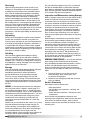
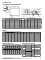
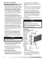
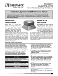
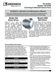
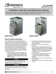
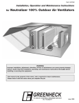
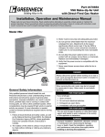
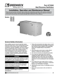
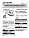
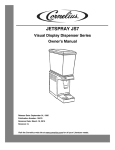
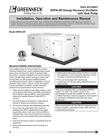
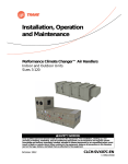
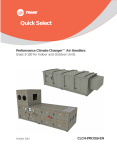
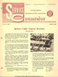
Part #464496 Low-Profile Fan Coil ® Installation, Operation and Maintenance Manual Please read and save these instructions. Read carefully before attempting to assemble, install, operate or maintain the product described. Protect yourself and others by observing all safety information. Failure to comply with instructions could result in personal injury and/or property damage! Retain instructions for future reference. Model LFC General Safety Information Only qualified personnel should install this unit. Personnel should have a clear understanding of these instructions and should be aware of general safety precautions. Improper installation can result in electric shock, possible injury due to coming in contact with moving parts, as well as other potential hazards. Other considerations may be required if high winds or seismic activity are present. If more information is needed, contact a licensed professional engineer before moving forward. 1. Follow all local electrical and safety codes, as well as the National Electrical Code (NEC), the National Fire Protection Agency (NFPA), where applicable. Follow the Canadian Electric Code (CEC) in Canada. DANGER Always disconnect power before working on or near a unit. Lock and tag the disconnect switch or breaker to prevent accidental power up. 2. The rotation of the wheel is critical. It must be free to rotate without striking or rubbing any stationary objects. 3. Motor must be securely and adequately grounded. 4. Do not spin fan wheel faster than the maximum cataloged fan rpm. Adjustments to fan speed significantly affects motor load. If the fan RPM is changed, the motor current should be checked to make sure it is not exceeding the motor nameplate amps. 5. Do not allow the power cable to kink or come in contact with oil, grease, hot surfaces, or chemicals. Replace cord immediately if damaged. 6. Verify that the power source is compatible with the equipment. 7. Never open blower access doors while the fan is running. CAUTION When servicing the unit, motor may be hot enough to cause pain or injury. Allow motor to cool before servicing. 1 Model LFC Low-Profile Fan Coil ® Receiving Upon receiving the product, check to make sure all items are accounted for by referencing the bill of lading to ensure all items were received. Inspect each crate for shipping damage before accepting delivery. Notify the carrier if any damage is noticed. The carrier will make notification on the delivery receipt acknowledging any damage to the product. All damage should be noted on all the copies of the bill of lading which is countersigned by the delivering carrier. A Carrier Inspection Report should be filled out by the carrier upon arrival and reported to the Traffic Department. If damaged upon arrival, file claim with carrier. Any physical damage to the unit after acceptance is not the responsibility of Greenheck Fan Corporation. Unpacking Verify that all required parts and the correct quantity of each item have been received. If any items are missing, report shortages to your local representative to arrange for obtaining missing parts. Sometimes it is not possible that all items for the unit be shipped together due to availability of transportation and truck space. Confirmation of shipment(s) must be limited to only items on the bill of lading. Handling Units are to be rigged and moved by the lifting brackets provided or by the skid when a forklift is used. Location of brackets varies by model and size. Handle in such a manner as to keep from scratching or chipping the coating. Damaged finish may reduce ability of unit to resist corrosion. Storage Units are protected against damage during shipment. If the unit cannot be installed and operated immediately, precautions need to be taken to prevent deterioration of the unit during storage. The user assumes responsibility of the unit and accessories while in storage. The manufacturer will not be responsible for damage during storage. These suggestions are provided solely as a convenience to the user. INDOOR — The ideal environment for the storage of units and accessories is indoors, above grade, in a low humidity atmosphere which is sealed to prevent the entry of blowing dust, rain, or snow. Temperatures should be evenly maintained between 30°F (-1°C) and 110°F (43°C) (wide temperature swings may cause condensation and “sweating” of metal parts). All accessories must be stored indoors in a clean, dry atmosphere. Remove any accumulations of dirt, water, ice, or snow and wipe dry before moving to indoor storage. To avoid “sweating” of metal parts allow cold parts to reach room temperature. To dry parts and packages use a portable electric heater to get rid of any moisture build up. Leave coverings loose to permit air circulation and to allow for periodic inspection. 2 Model LFC Low-Profile Fan Coil The unit should be stored at least 3½ in. (89 mm) off the floor on wooden blocks covered with moisture proof paper or polyethylene sheathing. Aisles between parts and along all walls should be provided to permit air circulation and space for inspection. Inspection and Maintenance during Storage While in storage, inspect fans once per month. Keep a record of inspection and maintenance performed. If moisture or dirt accumulations are found on parts, the source should be located and eliminated. At each inspection, rotate the fan wheel by hand ten to fifteen revolutions to distribute lubricant on motor. Every three months, the fan motor should be energized. If paint deterioration begins, consideration should be given to touch-up or repainting. Fans with special coatings may require special techniques for touch-up or repair. Machined parts coated with rust preventive should be restored to good condition promptly if signs of rust occur. Immediately remove the original rust preventive coating with petroleum solvent and clean with lint-free cloths. Polish any remaining rust from surface with crocus cloth or fine emery paper and oil. Do not destroy the continuity of the surfaces. Wipe thoroughly clean with Tectyl® 506 (Ashland Inc.) or the equivalent. For hard to reach internal surfaces or for occasional use, consider using Tectyl® 511M Rust Preventive or WD-40® or the equivalent. REMOVING FROM STORAGE — As units are removed from storage to be installed in their final location, they should be protected and maintained in a similar fashion, until the equipment goes into operation. Prior to installing the unit and system components, inspect the unit assembly to make sure it is in working order. 1. Check all fasteners, set screws on the fan, wheel, bearings, drive, motor base, and accessories for tightness. 2. Rotate the fan wheel(s) by hand and assure no parts are rubbing. Service Clearance Units require service clearance for: • filter replacement • coil and drain pan inspection - cleaning, and replacement • motor and drive inspection - maintenance and replacement Access panels are provided for inspection and cleaning of unit components. Allow service clearance of 26 inches for removal of filters. Allow a service clearance equal to the unit width for removal of coils and drain pan. ® Table of Contents Lifting Instructions Installation Unit Layout . . . . . . . . . . . . . . . . . . . . . . . . . . . . . . .3 Lifting / Hanging Instructions. . . . . . . . . . . . . . . . . 3 Dimensions / Weights. . . . . . . . . . . . . . . . . . . . . . . 4 Filter Sizes / Quantity. . . . . . . . . . . . . . . . . . . . . . . 4 Coil Dimensions . . . . . . . . . . . . . . . . . . . . . . . . . 5-6 Start-Up System Start-Up. . . . . . . . . . . . . . . . . . . . . . . . . . . 7 Troubleshooting Blower. . . . . . . . . . . . . . . . . . . . . . . . . . . . . . . . . . . Motor Overamps. . . . . . . . . . . . . . . . . . . . . . . . . . . Insufficient / Too Much Airflow. . . . . . . . . . . . . . . . Excessive Noise or Vibration. . . . . . . . . . . . . . . . . Greenheck’s Low-Profile Fan Coil (LFC) should be lifted by the factory supplied lifting lugs or frame rails and a spreader bar (by others) to prevent damage from occurring to the equipment (see Figure 1). Avoid twisting or uneven lifting of equipment. Do not lift equipment by coil connections or headers. The unit must remain upright during lifting. All access doors and panels must be closed during lifting to avoid damage. 8 8 8 8 Spreader Bar Frame Rails Start-Up Coil Module. . . . . . . . . . . . . . . . . . . . . . . . . . . . 9-10 Drain Pan / Drain Trap . . . . . . . . . . . . . . . . . . . . . 10 Maintenance Fan. . . . . . . . . . . . . . . . . . . . . . . . . . . . . . . . . . . . . 11 Coil. . . . . . . . . . . . . . . . . . . . . . . . . . . . . . . . . . . . . 12 Drain Pan. . . . . . . . . . . . . . . . . . . . . . . . . . . . . . . . 12 Reference Lifting Lugs Start-Up Documentation. . . . . . . . . . . . . . . . . . . . 12 Maintenance Log . . . . . . . . . . . . . . . . . . . . . . 13-15 Warranty . . . . . . . . . . . . . . . . . . . . . . . . . Backcover Figure 1 Hanging Instructions Unit Layout Airflow 4 The LFC should be hung by the factory supplied lifting lugs or field supplied frame rails as shown respectively in Figures 2 and 3. All hanging brackets must be used to mount the unit. The LFC is available with both external neoprene and spring isolation options. 5 6 3 2 5 1 1. Fan Section 2. Coil Section • Chilled Water • DX Coils Figure 2 • Hot Water • Steam Coils 3. Inlet Filter Vertical inlet filter with quarter-turn fasteners 4. Lifting Lugs/Hanging Brackets Six (6) lifting lugs for each unit 5. Side Access Panels Right and left access to each unit. (Image shows panels removed). Figure 3 6. 11⁄4 inch knockout is provided for the recommended electrical wiring penetration or disconnect switch. ® Model LFC Low-Profile Fan Coil 3 Unit Dimensions F B A C H G E K J D I Top View Unit Size 15 20 25 30 45 50 65 85 w/o Filter 40 40 40 45 45 48 52 52 I w/ 2 in. Filter 42 42 42 47 47 50 54 54 Elevation View w/ 4 in. Filter 44 44 44 49 49 52 56 56 J K Width 8.0 11.0 13.0 15.5 14.25 16.75 21.75 21.75 11.0 14.0 16.0 18.5 18.5 21.0 26.0 26.0 38 38 38 38 50 50 50 62 Inlet Height Width 9.0 36 12.0 36 14.0 36 16.5 36 16.5 48 19.0 48 24.0 48 24.0 60 Outlet Height Width 4.0 6.75 6.5 6.75 8.0 8.5 9.0 9.0 9.0 10.0 10.25 10.0 12.0 12.75 12.0 15.0 All dimensions are in inches. Weights Unit Size 15 20 25 30 45 50 65 85 Fan w/ Drain Pan Fan Motor Total 128 50 178 151 50 201 175 60 235 199 60 259 250 75 325 316 75 391 405 75 480 450 100 550 1 Row 2 Row 4 Row 6 Row 8 Row 2 in. Vertical Filter 4 in. Vertical Filter 25 32 38 45 51 58 64 71 31 41 51 61 70 80 90 100 44 61 77 94 110 127 143 160 60 83 106 129 152 175 198 221 75 105 135 165 195 225 255 285 5 6 8 9 11 12 14 15 8 10 13 15 17 19 22 24 All weights are shown in pounds (lbs.) Motor weights may vary depending on enclosure type and horsepower. Mounting Dimensions Unit Size 15 20 25 30 45 50 65 85 A 40 40 40 45 45 48 52 52 Horizontal Hanging B C D E F 18.25 19.75 38 43 1 19 19 38 43 1 19 19 38 43 1 19 24 38 43 1 19 24 50 55 1 19 27 50 55 1 19 31 50 55 1 19 31 62 67 1 All dimensions are in inches. Filter Sizes and Quantity G 0.5 0.5 0.5 0.5 0.5 0.5 0.5 0.5 H 2.5 2.5 2.5 2.5 2.5 2.5 2.5 2.5 Size 15 20 25 30 45 50 65 85 Filter Size 9 x 18 12 x 12 12 x 24 14 x 18 16 x 16 16 x 20 16 x 24 18 x 24 24 x 24 12 x 24 24 x 24 Qty 2 Face Area (ft 2) 1.8 1 2.5 2 3.0 1 3.4 2 2 2 1 2 4.8 5.4 7.2 8.9 All dimensions are in inches. 4 Model LFC Low-Profile Fan Coil ® Coil Dimensions Hot Water • 1 and 2 Row Unit Size B 15 B Copper Sweat 3 Airflow Outlet A 3.75 0.75 2 1 1.5 Drain Connection 0.25 vent and drain supplied. Right side connection shown. Hot Water • 4 Row 3 Airflow Outlet A 3.75 0.75 2 1 1.5 Drain Connection 0.25 vent and drain supplied. Right side connection shown. Steam • 1 and 2 Row NOTE Fluid enters the coil from the bottom connection (Inlet) and exits from the top (Outlet). 3 Airflow Outlet A C 2 1.5 Right side connection shown. 0.75 1 Drain Connection A B 15 7.63 0.75 20 10.13 0.75 25 12.63 0.875 30 15.13 0.875 45 15.13 0.875 50 17.63 1.375 65 22.63 1.375 85 22.63 1.375 All dimensions are in inches. NOTE With airflow from left to right, the fluid enters the coil from the bottom connection (Inlet) and exits from the top (Outlet). The other two coil connections should be capped off (Cap). Unit Size B Steel MPT 7.63 0.75 20 10.13 0.75 25 12.63 0.875 30 15.13 0.875 45 15.13 0.875 50 17.63 1.125 65 22.63 1.375 85 22.63 1.375 All dimensions are in inches. Unit Size B Copper Sweat ® A A B 15 7.0 1.5 20 6.94 1.5 25 8.19 2.5 30 9.44 2.5 45 9.44 2.5 50 10.69 2.5 65 13.19 2.5 85 13.19 2.5 All dimensions are in inches. C 3.81 3.56 3.81 3.56 3.56 4.81 3.56 3.56 NOTE Steam enters the coil from the center connection (Inlet) and exits from the bottom (Outlet). Model LFC Low-Profile Fan Coil 5 Chilled Water • 4, 6 or 8 Row Unit Size B Copper Sweat B Copper Sweat Airflow 3 Airflow 3 Outlet B Copper Sweat Airflow Outlet 3 A A Outlet 3.75 A 0.75 3.75 2 0.75 1 Drain Connection 21.5 1 Drain Connection 1.5 0.75 shown. 0.25 vent and drain supplied. 3.75 Right side connection 2 1 Drain Connection 1.5 Direct Expansion (DX) • Single Circuit • 4, 6 or 8 Row Airflow 3 Airflow 3 B Copper Sweat B Copper Sweat C Airflow Copper Sweat 3 C Copper B Sweat A Copper Sweat A 3.75 C 3.75 Copper Sweat Outlet Outlet 0.75 2 21.5 A 1 1.5 3.75 0.751 Drain Connection Drain Connection Outlet 4 row A B 15 7.63 0.75 0.75 1/1 1.375 03/13/2009 20 10.13 0.75 0.75 1/1 1.375 25 12.63 0.875 0.875 1.375 Chilled Water 8 Row 30 15.13 0.8754,6 or 0.875 1.375 1/1B (8 Row) Chilled 4,6 or0.875 8Row) Row A Water B (4 Row) B (6 Unit Size 45 15.13 0.875 1.375 LCF-15 7.63 A 0.75 0.75 1.375 B (4 Row) 1.375 B (6 Row) B (8 Row) Unit Size 50 17.63 1.375 1.625 LFC-20 10.13 0.75 0.75 1.375 LCF-15 7.63 0.75 0.75 1.375 LFC-25 12.63 0.875 0.875 1.375 65 22.63 1.375 1.375 1.625 LFC-20 10.13 0.75 0.75 1.375 Water0.875 4,6 or 80.875 Row 1.375 LFC-30Chilled 15.13 LFC-25 12.63 0.875 0.875 1.375 LFC-45 15.13 0.875 0.875 1.375 85 22.63 1.375 1.375 1.625 LFC-30 15.13 0.875 0.875 1.375 A B (4 Row) B (6 Row) B (8 Row) Unit Size LFC-50 17.63 1.375 1.375 1.625 LFC-45 15.13 0.875 0.875 1.375 22.63 All dimensionsLFC-65 are in inches. 1.375 1.375 1.625 LCF-15 7.63 0.75 0.75 1.375 LFC-50 LFC-85 LFC-20 LFC-65 LFC-25 LFC-85 LFC-30 LFC-45 0.75 2 17.63 22.63 10.13 22.63 12.63 22.63 15.13 15.13 17.63 22.63 22.63 1.375 1.375 0.75 1.375 0.875 1.375 0.875 0.875 1.375 1.375 1.375 1.375 1.375 0.75 1.375 0.875 1.375 0.875 0.875 1.375 1.375 1.375 1.625 1.625 1.375 1.625 1.375 1.625 1.375 1.375 1.625 1.625 1.625 NOTE With airflow from left to right, the fluid enters the coil LFC-50 LFC-65 from the bottom connection (Inlet) and exits from the LFC-85 top (Outlet). The other two coil connections should be capped off (Cap) Unit Size A 4 row B 6 row C B 8 row C B C 15 5.75 0.625 0.625 0.625 0.625 0.625 1.375 (DX)-Single Circuit-4,6 or 8 Row 20 7.0 Direct 0.625 Expansion 0.625 0.625 0.625 0.625 1.375 Direct Expansion (DX)-Single Circuit-4,6 or 8 Row B (6 Row) B (8 Row) B (4 Row) C (6 C (4 Row) Unit Size A 25 8.0 0.875 1.375 0.875 1.375 0.875 1.375Row) MSCF-15 5.75A 0.625 0.625 0.625 0.625 0.625 B (6 Row) B (8 Row) B (4 Row) C (6 Row) C (4 Row) Unit Size 30 9.5 0.875 1.375 0.875 1.375 0.875 MSCF-20 7.0 0.625 0.625 1.375 0.625 0.625 0.625 MSCF-15 5.75 0.625 0.625 0.625 0.625 0.625 MSCF-25 1.375 1.375 8.0 0.875 0.875 0.875 45 9.5 0.875 1.375 0.875 1.375 MSCF-20 0.625 0.625 1.375 0.625 0.625 0.625 0.875 MSCF-30 Direct Expansion (DX)-Single Circuit-4,6 or 8 Row 1.375 1.375 9.57.0 0.875 0.875 0.875 MSCF-25 1.375 1.375 8.0 0.875 0.875 0.875 MSCF-45 1.375 1.375 9.5 0.875 0.875 1.625 0.875 50 10.75 0.875 1.375 1.125 1.375 0.875 MSCF-30 9.5 MSCF-50 B1.125 (60.875 Row) B0.875 (80.875 Row) B0.875 (40.875 Row) C1.375 (61.375 Row) C1.375 (41.375 Row) Unit Size 10.75 A MSCF-45 1.375 1.375 9.5 0.875 0.875 0.875 1.375 1.375 13.00 1.125 1.125 1.125 65 13.00 MSCF-65 1.125 1.375 1.125 1.375 1.125 1.625 MSCF-15 5.75 0.625 0.625 0.625 0.625 0.625 MSCF-50 1.375 1.375 10.75 0.875 1.125 0.875 MSCF-85 1.375 1.375 13.00 1.125 1.125 1.125 MSCF-20 7.0 0.625 0.625 0.625 0.625 0.625 MSCF-65 1.375 1.375 1.125 13.00 1.125 1.125 1.625 1.125 1.375 85 13.00 1.125 1.375 1.125 MSCF-25 1.375 1.375 8.0 0.875 0.875 0.875 MSCF-85 1.375 1.375 13.00 1.125 1.125 1.125 MSCF-30 1.375 1.375 9.5 0.875 0.875 0.875 All dimensions are in inches. MSCF-45 1.375 1.375 9.5 0.875 0.875 0.875 MSCF-50 10.75 13.00 13.00 1.375 0.875 1.125 1.375 0.875 1.125 1.125 1.375 1.375 1.125 NOTE 1.125 1.375 1.375 1.125 1.125 With airflow from left to right, the fluid enters the coil from the center connection (Inlet) and exits from the bottom (Outlet). The other coil connections should be capped off (Cap). MSCF-65 MSCF-85 Distributor hookup is done inside module through 2-inch access hole. 1 1.5 Drain Connection Right side connection shown. JOHNSONRI JOHNSONRI 03/13/2009 6 03/13/2009 row 8 row JOHNSONRI B B C (8 R 1.3 C 1.3 1.3 1.3 1.3 C1.6 (8 1.6 1 1.6 1 1 1 1 1 1 1 Direct ExpansionAirflow (DXI) • Dual Circuit with 50/50 Face Interlaced Construction • 4, 6 or 8 Row 3 Direct Expansion (DXI)-Dual Circuit with 50/50 Face Airflow 3 C Copper Sweat Unit Size C Copper Sweat Airflow D Copper Sweat D Copper C Sweat 3.75 D Copper Sweat3.75 A B A Outlet Outlet 0.75 2 21.5 1.5 3.75 B A 0.751 Drain Connection 1 Drain Connection Outlet 0.75 2 1.5 1 Drain Connection Distributor hookup is done inside module through 2-inch access hole. Right side connection shown. 6 Model LFC Low-Profile Fan Coil B MSCF-30 Unit Size C 12.00A 12.00 12.00 13.50 12.00 17.00 13.50 17.00 17.00 A 17.00 12.00 12.00 13.50 17.00 17.00 7.00 B 7.00 7.00 7.75 7.00 9.50 7.75 9.50 9.50 B 9.50 7.00 7.00 7.75 9.50 9.50 D C 0.625 C (4 Row) 0.625 0.625 0.625 0.625 0.875 0.625 0.875 C (40.875 Row) 0.875 0.625 0.625 0.625 0.875 0.875 D 0.625 D (4 Row) 0.625 0.625 0.625 0.625 0.875 0.625 0.875 D (40.875 Row) 0.875 0.625 0.625 0.625 0.875 0.875 C 0.625 C (6 Row) 0.625 0.625 0.625 0.625 0.875 0.625 0.875 C (60.875 Row) 0.875 0.625 0.625 0.625 0.875 0.875 D 0.875 D (6 Row) 0.875 0.875 0.875 0.875 1.125 0.875 1.125 D (61.125 Row) 1.125 0.875 0.875 0.875 1.125 1.125 0.625 C (8 Row) 0.625 0.625 0.625 0.625 0.875 0.625 0.875 C (80.875 Row) 0.875 0.625 0.625 0.625 0.875 0.875 Direct Expansion (DXI)-Dual Circuit with 50/50 Face 12.00 7.00 0.625 0.625 Construction-4,6 0.625 0.875 0.625 Interlaced or 0.875 8 Row MSCF-45 MSCF-30 MSCF-50 MSCF-45 MSCF-65 MSCF-50 MSCF-85 MSCF-65 Unit Size 3 B Copper Sweat A Interlaced(DXI)-Dual Construction-4,6 or 8 Row Direct Expansion Circuit with 50/50 Face 4 row C (4 Row)Construction-4,6 6D (4row 8 or row RowC (8 Row) C (6 Row) Row) D (68Row) A Interlaced B Unit Size 30 45 12.00 7.00 0.625 MSCF-85 50 13.50 7.75 0.625 MSCF-30 MSCF-45 65 17.00 9.50 0.875 MSCF-50 MSCF-65 85 17.00 9.50 0.875 MSCF-85 All dimensions are in inches. 0.625 0.625 0.875 0.875 0.625 0.625 0.875 0.875 0.875 0.875 1.125 1.125 0.625 0.625 0.875 0.875 0.875 1.125 1.125 1.125 D( D D NOTE LFC COIL D The first suction header on the entering air side of LFC COIL D the coil is circuited to the top distributor. With airflow from left to right, the fluid enters the coil from the LFC COIL D center connection (Inlet) and exits from the bottom (Outlet). The other coil connections should be capped off (Cap). ® System Start-Up 4. Air Volume Check and Measurement For proper unit function and safety, follow everything in this start-up procedure in the order presented. This is to be done after the electrical connections are complete. PRE-START CHECK LIST 1. Disconnect and lock-out all power switches to fan. 2. Check all fasteners, set screws and locking collars on the fan, bearings, drive, motor base and accessories for tightness. 3. Rotate the fan wheel by hand and assure no parts are rubbing. 4. Check the V-belt drive for proper alignment and tension. special tools required • Voltage Meter • Tachometer • Amperage Meter 1. Check Voltage Before starting the unit, compare the supplied voltage with the unit’s nameplate voltage and the motor voltage. Units are not provided with thermal overload protection unless a control center has been ordered with the unit or the motor has been selected with thermal overload protection. Along with the building balance, the unit’s air volume (cfm) should be measured and compared with its rated air volume. This unit is flexible for varying air volume, but the actual air volume should be known for making final adjustments. The most accurate way to measure the air volume is by using the pitot traverse method in the ductwork away from the blower. Other methods can be used, but should be proven and accurate. To adjust the air volume, change the fan rpm or the system losses. See Troubleshooting section in this guide. 5. Measure Motor Voltage, Amperage and Fan RPM All access doors must be installed. Measure and record the input voltage and motor amperage(s). To measure the fan RPM, the blower door will need to be removed. Minimize measurement time because the motor may over amp with the door removed. Compare measured amps to the motor nameplate full load amps and correct if over amping. See the Troubleshooting section in this guide. 2. Check Blower Rotation R R If the blower is rotating in the wrong direction, the unit will move some air, but T IO N T IO N TA TA perform properly. To will not O O AIRFLOW check the rotation, open the blower access door and run AIRFLOW the blower momentarily to determine the rotation. To reverse the rotation, turn the power off and use the following procedure: • For single phase units, rewire the motor per the instructions on the motor. • For three phase units, interchange any two power leads. This can be done at the motor starter. 3. Check for Vibration Check for unusual noise, vibration or overheating of bearings. Excessive vibration maybe experienced during initial start-up. Left unchecked, excessive vibration can cause a multitude of problems, including structural and/or component failure. Many conditions can be discovered by careful observation. If the problem is wheel unbalance, in-place balancing can be done providing there is access to the fan wheel. Generally, fan vibration and noise is transmitted to other parts of the building by the ductwork. If noise is an issue, we recommend using heavy canvas connections on the inlet of the fan. Refer to the Troubleshooting section of this manual if a problem develops. ® Model LFC Low-Profile Fan Coil 7 Troubleshooting Symptom Blower fails to operate Motor overamps Insufficient airflow Too much airflow Excessive noise or vibration 8 Possible Cause Corrective Action Blown fuse or open circuit breaker Replace fuse or reset circuit breaker and check amps Broken fan belt Replace Defective motor or capacitor Replace Motor starter overloaded Reset starter and check amps Airflow too high Check airflow and adjust drives if needed Static pressures are higher or lower than design If higher, ductwork should be improved If lower, fan RPMs should be lower Blower rotation is incorrect Check rotation and correct Motor voltage incorrect Check motor nameplate and supplied voltage Motor horsepower too low See specifications and catalog for fan curves to determine if horsepower is sufficient Shorted windings in motor Replace motor Mixing box damper not fully open Adjust damper linkage or replace damper motor System static pressure too high Improve ductwork to eliminate losses using good duct practices Blower speed too low Check for correct drives and RPMs with catalog data Mixing box dampers closed Open and adjust Dirty or clogged filters Clean or replace Leaks in ductwork Repair Elbows, or other obstructions may restrict fan outlet Correct or improve ductwork Belt slippage Adjust belt tension Blower fan speed too high Check for correct fan RPM Filter(s) not in place Install filters Insufficient static pressure (airflow resistance) Induce static pressure into system ductwork Wheel rubbing on housing Center wheel Loose wheel on shaft Tighten wheel setscrew Loose motor or blower sheave Tighten sheave setscrew Belts too loose Adjust belt tension after 24 hours of operation Belts too tight Loosen to maintain 3/8 inch deflection per ft. of span between sheaves Worn belt Replace Motor base or blower loose Tighten mountings bolts Worn bearings Replace Bearing and drive alignment Realign Motor out of balance Replace Wheel out of balance Replace or rebalance Sheaves eccentric or out-of-balance Replace or rebalance Accumulation of material on wheel Clean wheel and housing Model LFC Low-Profile Fan Coil ® Start-Up of Coil Module Hot Water, Chilled Water Coils 1. Piping should be in accordance with accepted industry standards. Pipework should be supported independently of the coils. Water pipes are copper with sweat connections. USE WET TOWEL TO AVOID BURNING COIL CONNECTION GROMMETS. When installing coupling, do not apply undue stress to the connection extending through the unit. Use a back-up pipe wrench to avoid breaking the weld between coil connection and header. 2. Connect the water supply to the bottom connection on the air-leaving side and the water return to the top connection on the air-entering side. The extra bottom connection can be used for an auxiliary manual drain connection, and the extra top connection may be used for an automatic air vent or the extra connections can be capped. To ensure proper venting, an external air vent in the piping is recommended. Connecting the supply and/or return in any other manner will result in very poor performance. CAP UNUSED CONNECTIONS. 3. The air vent at the uppermost point should be temporarily opened during system start-up to release all of the air from the coil. To maintain heat transfer capacity, periodically vent any air in the coil. Vent is to be located behind the connections side access door. 4. Water coils are not normally recommended for use with entering air temperatures below 40°F. No control system can be depended on to be 100% safe against freeze-up with water coils. Glycol solutions or brines are the only safe media for operation of water coils with low entering air conditions. WARNING Continuous water circulation through the coil at all times is highly recommended. 5. Pipe sizes for the system must be selected on the basis of the head (pressure) available from the circulation pump. Piping should be in accordance with accepted industry standards. 6. For chilled water coils, the condensate drain pipe should be sized adequately to ensure the condensate drains properly. See Drain Pan Traps section and related drawing. Direct Expansion (DX) Coils 1. Piping should be in accordance with accepted industry standards. Pipework should be supported independently of the coils. Undue stress should not be applied at the connection to coil headers. ® 2. The condensate drain pipe should be sized adequately to ensure the condensate drains properly. See Drain Pan Traps section and related drawing. 3. When connecting suction and liquid connections, make sure the coil is free from all foreign material. Make sure all joints are tight and free of leakage. 4. Dual circuits are recommended to be run by two compressors. One compressor with the appropriate valves and piping can be used but is not recommended. Greenheck does not supply compressor or condensing units, for further instruction on DX coil installation and operation, contact your compressor and/or condenser manufacturer. DXI coils have dual connections and should be used with two compressors. WARNING Standard unit insulation of 1.5 lbs. density has an insulation R-value of 3.7. For applications where the unit discharge temperatures are below 55°F. and the unit is installed in a warm, humid environment, additional insulation may need to be applied to the exterior of the unit to prevent condensation. Steam Coils Application Recommendations Satisfactory operation and service life are best ensured when coils are installed with proper piping, trap and support arrangement. The following notes and drawing are recommended for the coil unit installation and operation. General am Ste Return Main Main Strainer 1. Provide Gate Valve separate Control Valve Modulating Two-Position supports and hangers for the unit and the piping. Float & Thermostat Trap Check Valve Vacuum Breaker 2. Be certain that adequate piping flexibility is provided. Stresses resulting from expansion of closely coupled piping and coil arrangement can cause serious damage. Model LFC Low-Profile Fan Coil 9 Steam Coils, General - continued Freezing Conditions (entering air below 35°F) 3. Standard steam coils are pitched in the casings when installed for horizontal airflow. The casing must be level after the unit is installed for proper condensate drainage. If condensate is not removed, the coil will suffer from water hammering and will have a shortened life. On vertical airflow applications, the coils must be pitched when installed. 1. 5 PSI steam must be supplied to the coil at all times. 4. Do not reduce pipe size at the coil return connection. Carry return connection size through the dirt pocket, making the reduction at the branch leading to the trap. 5. It is recommended that vacuum breakers be installed on all applications to prevent retaining condensate in the coil. Generally, the vacuum breaker is to be connected between the coil inlet and the return main. The vacuum breaker should be open to the atmosphere and the trap design should allow venting of large quantities of air. 6. Do not attempt to lift condensate when using modulating or on-off control. 2. Modulating valves are not recommended. Control should be by means of face and bypass dampers. 3. Provision should always be made to thoroughly mix fresh air and return air before it enters the coil on return air units. Also, temperature control elements must be properly located to obtain true air mixture temperatures. 4. As additional protection against freeze-up, the trap should be installed sufficiently—far below the coil to provide an adequate hydrostatic head to ensure removal of condensate during an interruption in the steam pressure. Estimate 3 feet for each 1 PSI of trap differential required. 5. On start-up, admit steam to coil ten minutes before admitting outdoor air. 6. Provision must be made to close fresh air dampers if steam supply pressure falls below minimum specified. 7. Do not reduce the pipe size leaving the coil. Drain Pan / Drain Trap Traps Drain lines and traps should be run full size from the drain pan connection. Drain pans should have drain lines and traps to permit the condensate from the coils to drain freely. On all units with drain pans, the trap depth and the distance between the trap outlet and the drain pan outlet should be twice the static pressure (P) in the drain pan section under normal operation to assure the trap remains sealed. 1. Size traps in accordance with the manufacturer’s recommendations. Be certain that the required pressure differential will always be available. DO NOT UNDERSIZE. 2. Float and thermostatic or bucket traps are recommended for low pressure steam. On high pressure systems, bucket traps are normally recommended. The thermostatic traps should be used only for air venting. 3. Bucket traps are recommended for use with on-off control only. 4. Locate traps at least 12 inches below the coil return connection. 2P = minimum 2P = minimum Controls 1. On high pressure installations, a two-position steam valve with a face and bypass arrangement is preferred where modulating control is required. Drain Pan / Drain Trap 2. Modulating valves must be sized properly. DO NOT UNDERSIZE. 10 Model LFC Low-Profile Fan Coil ® Fan Maintenance Greenheck recommends these procedures to ensure trouble free operation of this unit. It is especially important to maintain heater units for clean and efficient operation. Most unit failures can Cbe attributed l oc k wi s e to poor setup or poor maintenance. CORRECT A record of maintenance performed on this unit should be kept. This information will provide essential information if problems areWRONG encountered. A section at WRONG WRONG the back of this manual is provided for recording the unit’s maintenance history. CAUTION When performing any maintenance on this unit, be sure that the power is disconnected and cannot be accidentally turned on. The control center disconnect can be locked in the off position. Two Weeks after Start-Up Belts - Belts tend to stretch after a period of time. They should be periodically checked for wear and tightness. Approximately 3/8 inch Belt Span Deflection = Belt Span 64 of deflection per ft. of span between sheaves is standard for belt tightness. When replacing belts, use the same type as supplied NOTE: For motors of 1 hp or less a smaller sliding base bracket with the unit. Matched is used to attach to blower. belts should always be used on units with multigroove pulleys. Replacement of belts can be accomplished by loosening the motor to the point where the belts can be removed by hand. Do not force belts on or off as this may cause breakage of cords leading to premature belt failure. Belts should be adjusted as above. Yearly Bearings — Most bearings are permanently lubricated and require no further lubrication under normal use. Normal use being considered -20ºF to 120ºF and in a relatively clean environment. Some bearings are relubricatable and will need to be regreased depending on fan use. Check your bearings for grease fittings to find out what type of bearing you have. If your fan is not being operated under normal use, bearings should be checked monthly for lubrication. Motors — Motor maintenance is generally limited to cleaning and lubrication (where applicable). Cleaning should be limited to the exterior surfaces only. Removing dust and grease buildup on motor housing assures proper motor cooling. Greasing of motors is intended only when grease fittings are provided. Many fractional motors are permanently lubricated and require no further lubrication. Motors supplied with grease fittings should be greased in accordance with manufacturer’s recommendations. When motor temperature does not exceed 104ºF (40ºC), the grease should be replaced after 2000 hours of running time as a general rule. Wheels — Wheels require very little attention when moving clean air. Occasionally, oil and dust may accumulate on the wheel causing imbalance. When this occurs the wheel and housing should be cleaned to assure smooth and safe operation. Inspect fan impeller and housing for fatigue, corrosion or wear. Routinely check all fasteners, set screws and locking collars on the fan, bearing, drive, motor base and accessories for tightness. Every Three (3) Months Filters - The filter in the unit should be inspected at least every three (3) months. Depending on the environment, filters could require changing or cleaning more or less often. The filters can be slid out of either side of the unit. If washable filters are installed, they can be washed in warm soapy water. An adhesive spray can be applied to increase filter efficiency. If disposable filters are installed, check by holding up to a light source. If light cannot pass through the filter, it should be replaced. Replacement filters should be of the same manufacturer and size. When reinstalling filters, be sure to install with the airflow in the correct direction indicated on the filter. ® Model LFC Low-Profile Fan Coil 11 Coil Maintenance Start-Up Documentation Coils must be clean to obtain maximum performance. Check once a year under normal operating conditions and, if dirty, brush or vacuum clean. Soiled fins reduce the capacity of the coil, demand more energy from the fan, and create an environment for odor and bacteria to grow and spread through the conditioned zone. High pressure water (400 psi or less) may be used to clean coils with fin thickness over 0.006 inches thick. Test the spray pressure over a small corner of the coil to determine if the fins will withstand the spray pressure. Job Information For coils with fragile fins or high fin density, foaming chemical sprays and washes are available. Many coil cleaners contain harsh chemicals, so they must be used with caution by qualified personnel only. Care must be taken not to damage the coils, including fins, while cleaning. CAUTION Fin edges are sharp. Winterizing Coils Coil freeze-up can be caused by such things as air stratification and failure of outdoor air dampers and/ or preheat coils. Routine draining of water cooling coils for winter shutdown cannot be depended upon as insurance against freeze-up. Severe coil damage may result. It is recommended that all coils be drained as thoroughly as possible and then treated in the following manner. Fill each coil independently with an antifreeze solution using a small circulating pump and again thoroughly drain. Check freezing point of antifreeze before proceeding to next coil. Due to a small amount of water always remaining in each coil, there will be diluting effect. The small amount of antifreeze solution remaining in the coil must always be concentrated enough to prevent freeze-up. NOTE: Carefully read instructions for mixing antifreeze solution used. Some products will have a higher freezing point in their natural state than when mixed with water. Job Name _ _________________________________ Address _ _________________________________ City ________________ _State ______ Zip_ ___________ Phone Number _ _________________________________ Contact Person _ _________________________________ Start-Up Company Information Service Oranization________________________________ Address ________________________________ City ________________ _State ______ Zip_ ___________ Phone Number ________________________________ Fax Number ________________________________ Start-Up Date ________________________________ Start-Up Personnel Name___________________________ Nameplate Information Unit Model Number________________________________ Volts_________________ Hertz_________ Phase ________ Amps________________Mark ________________________ Fan rpm______________ Unit Serial Number ________________________________ Field Start-Up Documentation oCheck blower rotation oCheck air volume (cfm) __________ Design __________ Actual oActual motor voltage oActual motor hertz oActual motor phase oActual motor amps Drive oFan RPM Range _ _________ _ _________ _ _________ _ _________ Volts Hertz Phase Amps __________ Minimum __________ Maximum Drain Pan Maintenance Drain pans in any air conditioning unit will have some moisture in them, therefore, algae and other organisms will grow due to airborne spores and bacteria. Periodic cleaning is necessary to prevent this buildup from plugging the drain and causing the drain pan to overflow. Inspect twice a year to avoid the possibility of overflow. Also, drain pans should be kept clean to prevent the spread of disease. Cleaning should be performed by qualified personnel. 12 Model LFC Low-Profile Fan Coil ® Maintenance Log Date___________________ Time______________ AM/PM Date___________________ Time______________ AM/PM Notes:___________________________________________ Notes:___________________________________________ _________________________________________________ _________________________________________________ _________________________________________________ _________________________________________________ _________________________________________________ _________________________________________________ _________________________________________________ _________________________________________________ Date___________________ Time______________ AM/PM Date___________________ Time______________ AM/PM Notes:___________________________________________ Notes:___________________________________________ _________________________________________________ _________________________________________________ _________________________________________________ _________________________________________________ _________________________________________________ _________________________________________________ _________________________________________________ _________________________________________________ Date___________________ Time______________ AM/PM Date___________________ Time______________ AM/PM Notes:___________________________________________ Notes:___________________________________________ _________________________________________________ _________________________________________________ _________________________________________________ _________________________________________________ _________________________________________________ _________________________________________________ _________________________________________________ _________________________________________________ Date___________________ Time______________ AM/PM Date___________________ Time______________ AM/PM Notes:___________________________________________ Notes:___________________________________________ _________________________________________________ _________________________________________________ _________________________________________________ _________________________________________________ _________________________________________________ _________________________________________________ _________________________________________________ _________________________________________________ Date___________________ Time______________ AM/PM Date___________________ Time______________ AM/PM Notes:___________________________________________ Notes:___________________________________________ _________________________________________________ _________________________________________________ _________________________________________________ _________________________________________________ _________________________________________________ _________________________________________________ _________________________________________________ _________________________________________________ Date___________________ Time______________ AM/PM Date___________________ Time______________ AM/PM Notes:___________________________________________ Notes:___________________________________________ _________________________________________________ _________________________________________________ _________________________________________________ _________________________________________________ _________________________________________________ _________________________________________________ _________________________________________________ _________________________________________________ ® Model LFC Low-Profile Fan Coil 13 Maintenance Log Date___________________ Time______________ AM/PM Date___________________ Time______________ AM/PM Notes:___________________________________________ Notes:___________________________________________ _________________________________________________ _________________________________________________ _________________________________________________ _________________________________________________ _________________________________________________ _________________________________________________ _________________________________________________ _________________________________________________ Date___________________ Time______________ AM/PM Date___________________ Time______________ AM/PM Notes:___________________________________________ Notes:___________________________________________ _________________________________________________ _________________________________________________ _________________________________________________ _________________________________________________ _________________________________________________ _________________________________________________ _________________________________________________ _________________________________________________ Date___________________ Time______________ AM/PM Date___________________ Time______________ AM/PM Notes:___________________________________________ Notes:___________________________________________ _________________________________________________ _________________________________________________ _________________________________________________ _________________________________________________ _________________________________________________ _________________________________________________ _________________________________________________ _________________________________________________ Date___________________ Time______________ AM/PM Date___________________ Time______________ AM/PM Notes:___________________________________________ Notes:___________________________________________ _________________________________________________ _________________________________________________ _________________________________________________ _________________________________________________ _________________________________________________ _________________________________________________ _________________________________________________ _________________________________________________ Date___________________ Time______________ AM/PM Date___________________ Time______________ AM/PM Notes:___________________________________________ Notes:___________________________________________ _________________________________________________ _________________________________________________ _________________________________________________ _________________________________________________ _________________________________________________ _________________________________________________ _________________________________________________ _________________________________________________ Date___________________ Time______________ AM/PM Date___________________ Time______________ AM/PM Notes:___________________________________________ Notes:___________________________________________ _________________________________________________ _________________________________________________ _________________________________________________ _________________________________________________ _________________________________________________ _________________________________________________ _________________________________________________ _________________________________________________ 14 Model LFC Low-Profile Fan Coil ® Maintenance Log Date___________________ Time______________ AM/PM Date___________________ Time______________ AM/PM Notes:___________________________________________ Notes:___________________________________________ _________________________________________________ _________________________________________________ _________________________________________________ _________________________________________________ _________________________________________________ _________________________________________________ _________________________________________________ _________________________________________________ Date___________________ Time______________ AM/PM Date___________________ Time______________ AM/PM Notes:___________________________________________ Notes:___________________________________________ _________________________________________________ _________________________________________________ _________________________________________________ _________________________________________________ _________________________________________________ _________________________________________________ _________________________________________________ _________________________________________________ Date___________________ Time______________ AM/PM Date___________________ Time______________ AM/PM Notes:___________________________________________ Notes:___________________________________________ _________________________________________________ _________________________________________________ _________________________________________________ _________________________________________________ _________________________________________________ _________________________________________________ _________________________________________________ _________________________________________________ Date___________________ Time______________ AM/PM Date___________________ Time______________ AM/PM Notes:___________________________________________ Notes:___________________________________________ _________________________________________________ _________________________________________________ _________________________________________________ _________________________________________________ _________________________________________________ _________________________________________________ _________________________________________________ _________________________________________________ Date___________________ Time______________ AM/PM Date___________________ Time______________ AM/PM Notes:___________________________________________ Notes:___________________________________________ _________________________________________________ _________________________________________________ _________________________________________________ _________________________________________________ _________________________________________________ _________________________________________________ _________________________________________________ _________________________________________________ Date___________________ Time______________ AM/PM Date___________________ Time______________ AM/PM Notes:___________________________________________ Notes:___________________________________________ _________________________________________________ _________________________________________________ _________________________________________________ _________________________________________________ _________________________________________________ _________________________________________________ _________________________________________________ _________________________________________________ ® Model LFC Low-Profile Fan Coil 15 Warranty Greenheck warrants this equipment to be free from defects in material and workmanship for a period of one year from the shipment date. Any units or parts which prove defective during the warranty period will be replaced at our option when returned to our factory, transportation prepaid. Motors are warranted by the motor manufacturer for a period of one year. Should motors furnished by Greenheck prove defective during this period, they should be returned to the nearest authorized motor service station. Greenheck will not be responsible for any removal or installation costs. As a result of our commitment to continuous improvement, Greenheck reserves the right to change specifications without notice. Greenheck Catalog IAH Series (MSCF-FC • MSCF-BI • LFC‑C • VFC-FC • VFCD-FC) provides additional information describing the equipment, fan performance, available accessories, and specification data. AMCA Publication 410-96, Safety Practices for Users and Installers of Industrial and Commercial Fans, provides additional safety information. This publication can be obtained from AMCA International, Inc. at www.amca.org. ® Phone: (715) 359-6171 • Fax: (715) 355-2399 • E-mail: [email protected] • Web site: www.greenheck.com LFC,Low-Profile Rev. 1, August Fan2004 Coil, Rev. 1, August 2004 16 464496 • LFC Copyright 2004 © Greenheck Fan Corporation