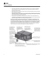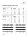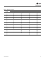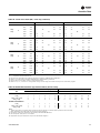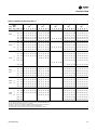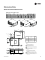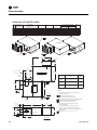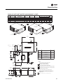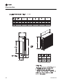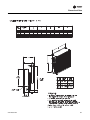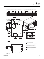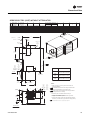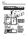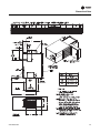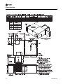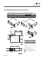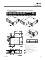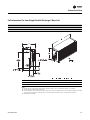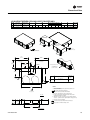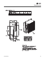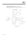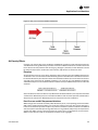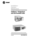
1
Product Catalog VariTrane™ Products Parallel and Series Fan-Powered VPCF, VPWF, VPEF, VSCF, VSWF, VSEF, LPCF, LPWF, LPEF, LSCF, LSWF, LSEF Variable-Air-Volume (VAV) System RA EA OA supply fan PA VAV box cooling coil variablespeed drive thermostat SA July 2013 VAV-PRC012-EN Introduction Fan-powered units offer energy savings due to intermittent fan control.The fan energizes only in heating mode when the space needs heat. Additional energy savings are obtained by using warm plenum air for free reheat. Motor heat is never wasted in parallel units.They are an excellent choice when minimal zone heating is needed. Figure 1. Parallel fan-powered terminal unit (L) & series fan-powered terminal units (R) Figure 2. Low height series: LSCF (L) & low height series: LSWF (R) Figure 3. Low height series: LSEF (L) & low height parallel: LPCF (R) Figure 4. Low height parallel: LPWF (L) & low height parallel: LPEF (R) Revision Summary VAV-PRC012-EN (16 Jul 2013). Updated proportional water valve design. VAV-PRC012-EN (27 June 2013). Updated controls information. Updated dimensions for units with attenuators. Trademarks Earthwise, VariTrane, VariTrac,Trane and theTrane logo are trademarks ofTrane in the United States and other countries. All trademarks referenced in this document are the trademarks of their respective owners. BACnet is a registered trademark of American Society of Heating, Refrigerating and AirConditioning Engineers (ASHRAE); LONMARK and LonTalk are registered trademarks of Echelon Corporation. © 2013Trane All rights reserved VAV-PRC012-EN Table of Contents Features and Benefits . . . . . . . . . . . . . . . . . . . . . . . . . . . . . . . . . . . . . . . . . . . . . . 5 Agency Certifications . . . . . . . . . . . . . . . . . . . . . . . . . . . . . . . . . . . . . . . . . . . . . . 13 Model Number Descriptions . . . . . . . . . . . . . . . . . . . . . . . . . . . . . . . . . . . . . . . . 15 Selection Procedure . . . . . . . . . . . . . . . . . . . . . . . . . . . . . . . . . . . . . . . . . . . . . . . 17 Performance Data . . . . . . . . . . . . . . . . . . . . . . . . . . . . . . . . . . . . . . . . . . . . . . . . 24 Parallel Fan-Powered Terminal Units . . . . . . . . . . . . . . . . . . . . . . . . . . . . . . 24 Series Fan-Powered Terminal Units . . . . . . . . . . . . . . . . . . . . . . . . . . . . . . . 35 Low Height Parallel Fan-Powered Terminal Units . . . . . . . . . . . . . . . . . . . . 47 Low Height Series Fan-Powered Terminal Units . . . . . . . . . . . . . . . . . . . . . 53 Electrical Data . . . . . . . . . . . . . . . . . . . . . . . . . . . . . . . . . . . . . . . . . . . . . . . . . . . . 59 Parallel Fan-Powered Terminal Units . . . . . . . . . . . . . . . . . . . . . . . . . . . . . . 59 Series Fan-Powered Terminal Units . . . . . . . . . . . . . . . . . . . . . . . . . . . . . . . 63 Low Height Parallel Fan-Powered Terminal Units . . . . . . . . . . . . . . . . . . . . 68 Low Height Series Fan-Powered Terminal Units . . . . . . . . . . . . . . . . . . . . . 70 Acoustics Data . . . . . . . . . . . . . . . . . . . . . . . . . . . . . . . . . . . . . . . . . . . . . . . . . . . 76 Parallel Fan-Powered Terminal Units . . . . . . . . . . . . . . . . . . . . . . . . . . . . . . 76 Series Fan-Powered Terminal Units . . . . . . . . . . . . . . . . . . . . . . . . . . . . . . . 85 Low Height Parallel Fan-Powered Terminal Units . . . . . . . . . . . . . . . . . . . . 92 Low Height Series Fan-Powered Terminal Units . . . . . . . . . . . . . . . . . . . . . 98 Dimensional Data . . . . . . . . . . . . . . . . . . . . . . . . . . . . . . . . . . . . . . . . . . . . . . . . 103 Parallel Fan-Powered Terminal Units . . . . . . . . . . . . . . . . . . . . . . . . . . . . . 103 Series Fan-Powered Terminal Units . . . . . . . . . . . . . . . . . . . . . . . . . . . . . . 109 Low Height Parallel Fan-Powered Terminal Units . . . . . . . . . . . . . . . . . . . 123 Low Height Series Fan-Powered Terminal Units . . . . . . . . . . . . . . . . . . . . 134 Mechanical Specifications: Fan-Powered . . . . . . . . . . . . . . . . . . . . . . . . . . . . 142 DDC Controls . . . . . . . . . . . . . . . . . . . . . . . . . . . . . . . . . . . . . . . . . . . . . . . . . . . 147 Control Logic . . . . . . . . . . . . . . . . . . . . . . . . . . . . . . . . . . . . . . . . . . . . . . . . . 147 DDC Remote Heat Control Options . . . . . . . . . . . . . . . . . . . . . . . . . . . . . . . 148 Tracer™ UC400 and UC210 Programmable BACnet Controllers . . . . . . . 152 Trane DDC VAV Controller Logic . . . . . . . . . . . . . . . . . . . . . . . . . . . . . . . . . 154 Flow Tracking Control . . . . . . . . . . . . . . . . . . . . . . . . . . . . . . . . . . . . . . . . . . 157 Tracer™ Programmable BACnet Controller — Unit Control Module . . . . 158 Trane LonMark DDC VAV Controller . . . . . . . . . . . . . . . . . . . . . . . . . . . . . . 160 Trane DDC VAV Controller Logic . . . . . . . . . . . . . . . . . . . . . . . . . . . . . . . . . 162 VAV-PRC012-EN 3 Flow Tracking Control . . . . . . . . . . . . . . . . . . . . . . . . . . . . . . . . . . . . . . . . . . 165 LonMark™ Direct Digital Controller—Unit Control Module . . . . . . . . . . . 166 Direct Digital Controller—Unit Control Module . . . . . . . . . . . . . . . . . . . . . 169 Wireless Comm Interface (WCI) . . . . . . . . . . . . . . . . . . . . . . . . . . . . . . . . . . 170 Wireless Receiver/Wireless Zone Sensor . . . . . . . . . . . . . . . . . . . . . . . . . . 172 DDC Zone Sensor . . . . . . . . . . . . . . . . . . . . . . . . . . . . . . . . . . . . . . . . . . . . . 173 CO2 Wall Sensor and Duct CO2 Sensor . . . . . . . . . . . . . . . . . . . . . . . . . . . . 174 DDC Zone Sensor with LCD . . . . . . . . . . . . . . . . . . . . . . . . . . . . . . . . . . . . . 176 Zone Occupancy Sensor . . . . . . . . . . . . . . . . . . . . . . . . . . . . . . . . . . . . . . . . 177 Factory or Field Wired Auxiliary Temperature Sensor . . . . . . . . . . . . . . . 178 Control Relay . . . . . . . . . . . . . . . . . . . . . . . . . . . . . . . . . . . . . . . . . . . . . . . . . 178 Two-Position Water Valve . . . . . . . . . . . . . . . . . . . . . . . . . . . . . . . . . . . . . . 179 Proportional Water Valve . . . . . . . . . . . . . . . . . . . . . . . . . . . . . . . . . . . . . . . 180 Differential Pressure Transducer . . . . . . . . . . . . . . . . . . . . . . . . . . . . . . . . . 181 Transformers . . . . . . . . . . . . . . . . . . . . . . . . . . . . . . . . . . . . . . . . . . . . . . . . . 182 Trane Actuator – 90 Second at 60 Hz Drive Time . . . . . . . . . . . . . . . . . . . . 183 Belimo Actuator – 95 Second Drive Time . . . . . . . . . . . . . . . . . . . . . . . . . . 184 Trane Spring Return Actuator . . . . . . . . . . . . . . . . . . . . . . . . . . . . . . . . . . . 185 VariTrane DDC Retrofit Kit . . . . . . . . . . . . . . . . . . . . . . . . . . . . . . . . . . . . . . 186 Retrofit Kit Actuator . . . . . . . . . . . . . . . . . . . . . . . . . . . . . . . . . . . . . . . . . . . 186 Silicon-Controlled Rectifier (SCR) . . . . . . . . . . . . . . . . . . . . . . . . . . . . . . . . 187 Pneumatic Controls . . . . . . . . . . . . . . . . . . . . . . . . . . . . . . . . . . . . . . . . . . . . 188 Controls Specifications . . . . . . . . . . . . . . . . . . . . . . . . . . . . . . . . . . . . . . . . . 203 Application Considerations . . . . . . . . . . . . . . . . . . . . . . . . . . . . . . . . . . . . . . . . 208 VAV System . . . . . . . . . . . . . . . . . . . . . . . . . . . . . . . . . . . . . . . . . . . . . . . . . . 208 Parallel vs. Series . . . . . . . . . . . . . . . . . . . . . . . . . . . . . . . . . . . . . . . . . . . . . 211 Low-Temperature Air . . . . . . . . . . . . . . . . . . . . . . . . . . . . . . . . . . . . . . . . . . 213 Energy Savings & System Controls . . . . . . . . . . . . . . . . . . . . . . . . . . . . . . . 216 Control Types . . . . . . . . . . . . . . . . . . . . . . . . . . . . . . . . . . . . . . . . . . . . . . . . 218 Flow Measurement and Control . . . . . . . . . . . . . . . . . . . . . . . . . . . . . . . . . 221 Reheat Options . . . . . . . . . . . . . . . . . . . . . . . . . . . . . . . . . . . . . . . . . . . . . . . 224 Insulation . . . . . . . . . . . . . . . . . . . . . . . . . . . . . . . . . . . . . . . . . . . . . . . . . . . . 226 Acoustics . . . . . . . . . . . . . . . . . . . . . . . . . . . . . . . . . . . . . . . . . . . . . . . . . . . . 226 Duct Design . . . . . . . . . . . . . . . . . . . . . . . . . . . . . . . . . . . . . . . . . . . . . . . . . . 230 Best Practices . . . . . . . . . . . . . . . . . . . . . . . . . . . . . . . . . . . . . . . . . . . . . . . . . 231 Unit Conversions . . . . . . . . . . . . . . . . . . . . . . . . . . . . . . . . . . . . . . . . . . . . . . 232 Additional VAV System and Product References . . . . . . . . . . . . . . . . . . . . 233 4 VAV-PRC012-EN Features and Benefits VariTrane™– VAV Leadership VariTrane variable-air-volume (VAV) units lead the industry in quality and reliability and are designed to meet the specific needs of today’s applications.This generation of VariTrane units builds upon the history of quality and reliability and expands the products into the most complete VAV offering in the industry. Parallel Fan-powered units offer energy savings due to intermittent fan control.The fan energizes only in heating mode when the space needs heat. Additional energy savings are obtained by using warm plenum air for free reheat. Motor heat is never wasted in parallel units.They are an excellent choice when minimal zone heating is needed. Series fan-powered units have fans which are always energized in occupied mode.They are common in applications such as conference rooms, cafeterias, etc., that desire constant airflow rates at all conditions. Low-height parallel units provide the energy savings of an intermittent fan with the flexibility of an 11"–11.5” casing height.This is a good choice for tight plenum spaces. Low-height series units have been used for years in projects with strict plenum height requirements. Units are available in 11.0" height. Energy Efficient Earthwise™ Systems Figure 5. Rooftop VAV (office building) A significant consumer of energy in commercial buildings is heating and air conditioning. One of the most energy-efficient HVAC solutions is the VAV system.This inherent system efficiency, along with high-quality, affordable DDC controls, has steadily increased demand for VAV systems over the years. VAV systems save significant energy, are able to deliver the required amount of ventilation air, and provide reliable occupant comfort. Energy saving features must go beyond a simpleVAV unit to incorporateVAV unit level and system level control strategies like: • VAV-PRC012-EN Ventilation Optimization-Combines demand-controlled ventilation (using either a time-of-day schedule, an occupancy sensor, or a carbon dioxide sensor) at the zone level with ventilation reset at the system level to deliver the required amount of outdoor air to each zone, while minimizing costly over-ventilation. 5 Features and Benefits • Fan Pressure Optimization- reduces supply fan energy by as much as 40% by intelligently reducing the pressure in the air distribution system to the lowest possible level without impacting occupant comfort. • Night setback reduces energy consumption during unoccupied periods by raising or lowering space temperature setpoints. • Supply AirTemperature Reset-reduces overall system energy use (balancing reduced cooling and reheat energy with increased fan energy) by raising the supply air temperature at part load, while avoiding elevated space humidity levels. • Electrically Commutated Motors (ECM) improve the efficiency of fan-powered VAV units. • LowTemperature Air Distribution can decrease overall system energy use by reducing airflows and the fan energy needed to move that air through the system. To determine the potential energy savings a VAV system can bring to your applications,Trane offers energy-modeling software like System Analyzer™ andTRACE 700®. WhenTRACE™ was introduced into the HVAC industry in 1972, the HVAC design and analysis program was the first of its kind and quickly became a defacto industry standard. It continues to grow with the industry meeting requirements for ASHRAE Standard 140, ASHRAE 90.1, and the LEED® Green Building Rating System and has now been approved by the IRS to certify energy savings for building owners. Contact your localTrane Sales Engineer for additional information. Control Flexibility—Trane factory installs more VAV controllers than any other manufacturer in the industry. In addition to Trane DDC controls and simple factory-mounting of non-Trane VAV controllers, Trane now offers a LonMark™ controller that is completely factory-commissioned to maximize installation quality and system reliability. Labor savings are maximized with Trane factory-commissioned controllers. Accurate Flow Ring—Housed and recessed within the air valve to provide flow ring handling/shipping protection. The patented flow ring provides unmatched airflow measurement accuracy. Rugged Air Valve—Trane air valves are heavy gage steel with a continuously welded seam to limit inlet deformation. This provides consistent and repeatable airflow across the flow ring with performance you can count on. Technologically Advanced "S Units— New super-quiet (SQ fan/motor/wheel assemblies engineered as an air deliver system to provide the most efficient design available in industry. For quiet comfort y can trust, rely on Trane SQ u Service Friendly: * Internal shaft visible through control box Tough Interlocking Panels— Rug cover sight hole for and rigidity are assured with Tra blade orientation patent-pending interlocking pan verification. * Same-side NEC jumpback clearance— provides all high- and low-voltage components on the same side to minimize field labor. Superior Metal Encapsulated * SQ fan-powered units have VariTrane Units are complete improved accessability to encapsulated edges to arrest internal components. Sliding fibers and prevent erosion in panels are standard which improve safety and allow Optional Narrow Corridor unit servicing with a single configuration — designed to minimize building Full Range of Insulation—Whether seeking optimal acoustical perf technician. material expenses by squeezing more into less space. or cleanability, Trane has a complete line of insulation options, incl Meets all NEC jumpback clearance requirements double-wall, matte-faced, foil-faced, closed cell, etc. for these extra-tight areas. Narrow Corridor Configuration not pictured here. Refer to Series Fan-Powered dimensional data for reference drawings. 6 VAV-PRC012-EN Features and Benefits Construction UL-listed products— Safety and reliability are vital in commercial construction. All VariTrane units are completely listed in accordance with UL -1995 as terminal units.This listing includes the VAV terminal with electric heaters. Additionally, all insulation materials pass UL 25/50 smoke and flame safety standards. AHRI Certified Performance— All VariTrane units are AHRI certified. AHRI 880 guarantees the pressure drop, flow performance, and acoustical performance provided is reliable and has been tested in accordance with industry accepted standards. AHRI 885 uses AHRI 880 performance and applies accepted industry methods to estimate expected “NC” sound levels within the occupied space. Casing Design— Interlocking Panels—VariTrane products are manufactured in the most state-of-the-art VAV facility in the world.The patent-pending interlocking panels are designed using integral I-beam construction technology.This limits deformation and creates tremendous product rigidity. An additional benefit is a smooth unit exterior with few exposed screws—ideal for exposed ceiling applications. VariTrane units are designed for use in systems that operate up to 5" w.c. of inlet pressure. Metal Encapsulated Edges—AllVariTrane units are complete with encapsulated edges to arrest cut fibers and prevent insulation erosion into the airstream.This is the standard of care in applications concerned with fiberglass erosion or projects with either double-wall or externally wrapped duct work. TheTrane Air Valve—is at the heart of VariTrane terminal units.This is where airflow is measured and controlled. Repeatability and ruggedness is vital.VariTrane products are the most rugged and reliable available. 18-gage Cylinder—limits deformation or damage during shipment and job site handling, and provides even airflow distribution across the flow ring for unmatched airflow measurement accuracy. Continuously Welded Seam — an automated weld process creates the highest quality continuous seam, which is “right” every time.The welded seam improves air valve rigidity and creates consistent and repeatable airflow across the flow measurement device.The result is a truly round cylinder every time, with no flat spots caused by lower quality crimping and riviting technologies. Flow Ring—TheTrane flow ring is time tested to perform under the most demanding conditions. Additionally,Trane’s patented flow ring is recessed within the air valve cylinder to reduce the potential for damage during job site handling and installation. VAV-PRC012-EN 7 Features and Benefits External Shaft—The simple design provides controller flexibility and is designed to facilitate actuator field replacement. Position Indicator—The position indicator shows current air valve position to aid in system commissioning. Many times this can be seen from the floor without climbing a ladder. External Actuator—This feature increases serviceability, control system compatibility, and actuator clutch access for simplified commissioning. Indoor Air Quality (IAQ) Features The oil embargo of the early 1970s created an energy crisis, which resulted in tighter buildings, and reduced ventilation rates. A fallout issue of tighter building construction was poor indoor air quality.This heightened IAQ awareness. IAQ issues have been featured in publications from the smallest towns to the largest cities. System design should consider applicable ventilation and IAQ standards.(See your localTrane Sales Engineer or visit www.trane.com for additional information). Good indoor air quality results from units and systems which: • Provide the required amount of ventilation air to each zone during all operating conditions • Limit particulates from entering occupied spaces • Allow proper access for periodic cleaning. Note: Access made easy on new VariTrane units, as shown on this Series Fan-Powered unit. VariTrane units are designed with simplified access and a full line of insulation options including: Matte-faced—Typical industry standard with reduced first cost. Closed-cell—This insulation has an R-value and performance equivalent to matte-faced insulation. The main difference is the reduction of water vapor transmission. Closed-cell is designed for use in installations with a high chance of water formation. (It has been used to coat the exterior of chiller evaporator barrels for many years.) Foil-faced—A fiberglass insulation with a thin aluminum coating on the air stream side to prevent fibers from becoming airborne.The aluminum lining is acceptable for many applications, however it is not as rugged as double-wall Double-wall—Premium insulation often used in many health care applications with insulation locked between metal liners.This eliminates the possibility for insulation entering the airstream and allows for unit interior wipe-down as needed. VariTrane VAV units are the most prepared IAQ units in the industry. The end result is a reliable product designed for peak performance, regardless of job site conditions or handling. 8 VAV-PRC012-EN Features and Benefits Tracer™ Building Automation System Tracer Building Automation System assures comfort within your building. Building controls have a bigger job description than they did a few years ago. It’s no longer enough to control heating and cooling systems and equipment. Sophisticated buildings require smarter technology that will carry into the future. Tracer™ controls provide the technology platform – mobile, easy-to-use, cloud-based, scalable and open - for the next generation of data-driven, technology-enabled services that are creating high performance buildings. With aTraneTracer Building Automation System, you’ll: • Reduce operating costs through energy management strategies • Consistently provide occupant comfort • Enjoy reliable operation with standard, pre-engineered and pretested applications • Easily troubleshoot and monitor either on site or from a remote location • Reduce installation time and simplify troubleshooting Whether factory-mounted or field-installed,Trane offers a wide range of controllers to suit virtually any application.These units are compatible with a variety of building types and can be used for new construction or renovation.Through extensive usability testing internally and with building operators, we’ve designed our controls for real world ease of use. (Additional control options and sequence-of-operations are located in the “Controls” section.) Trane VAV UCM DDC Controller DDC (communicating electronic)—DDC controllers are today’s industry standard. DDC controllers provide system-level data used to optimize overall SYSTEM performance. Variables such as occupied/unoccupied, minimum and maximum cfm and temperature, valve position, ventilation fraction, etc. are available on a simple twistedshielded wire pair. For additional information, see “Industry Issues: Energy Efficiency”. Note: One of many Trane DDC Control Options which are factory-installed, wired, calibrated, and fully tested before shipment. Trane DDC controllers provideTrane-designed solid-state electronics intended specifically for VAV temperature control in space comfort applications. DDC control capabilities include: • Pressure-independent (PI) operation—Provides airflow required by the room thermostat to maintain occupant comfort.The controller automatically adjusts valve position to maintain required airflow. Minimum and maximum airflow is factory-set and field-adjustable. • Factory-set airflow and temperature setpoints • Most advanced system integration in the industry. Tracer VV550 LonTalk™ Controllers LonTalk™ Controller Trane now offers a full line of LonTalk™ controllers designed for simple integration into ANY system which can communicate via the LonMark Space Comfort Control (SCC) protocol.These controllers are also completely factory-commissioned. VAV-PRC012-EN 9 Features and Benefits Tracer BACnet™ Controllers Trane now offers a full line of BACnet controllers designed for simple integration into any system which can communicate via the BACnet protocol.These controllers are factory-commissioned and shipped ready to be installed. UC210 BACnet Controller UC400 BACnet Controller Trane Wireless Comm Interface (WCI) WCI controller Provides wireless communication between theTracer SC, Tracer Unit Controllers, and BACnet™ Communication Interface (BCI) modules. TheTrane WCI is the perfect alternative toTrane’s BACnet wired communication links (for example – Comm links between aTracer SC andTracer UC400). Eliminating communication wire used between terminal products, zone sensors, and system controllers has substantial benefits. • Installation time and associated risks are reduced. • Projects are completed with fewer disruptions. • Future re-configurations, expansions, and upgrades are easier and more cost effective. Trane Wireless Zone Sensor Wireless Zone Sensor Provides wireless communication between the Unit Controller and the zone sensor.This is an alterntive to the wired zone sensor when access and routing of communicaiton cable is an issue. It also allows very flexible mounting and relocation of zone sensors 10 VAV-PRC012-EN Features and Benefits Pneumatic Controller Pneumatic Controller Pneumatic—Pneumatic controllers provide proven reliability and performance. A full line of options provide: • Highest quality PVR available, which maximizes zone temperature control. Pressure-independent operation • AllVariTrane pneumatic controllers use the patented flow sensor input to provide the most accurate performance available. Binary Input Controller Integration Options (Interfacing with other control systems) - Trane offers three ways to interface with other control systems. 1. UseTrane LonMark, factory-commissioned VAV controllers 2. UseTrane Binary Input Controller (BIC). BIC allows system control through binary logic.This means that a control system on an existing campus, or those seeking “Analog noncommunicating control” can control aTrane DDCVAV unit via basic binary contact closures, like relays, etc.This can be a cost effective interface option where a fullTrane DDC VAV System is not available. 3. UseTrane BACnet™ factory-commissioned VAV controllers. Factory-installed vs. Factory-commissioned: The terms factory-installed and factory-commissioned are often used interchangeably.Trane takes great pride in being the industry leader in factory-commissioned DDC controllers. Table differentiates these concepts. Factory-commissioned controllers provide the highest quality and most reliable units for yourVAV system. Additional testing verifies proper unit operation including occupied/unoccupied airflow, temperature setpoints, communication link functionality, and output device functionality.The benefits of factory-commissioning are standard on VariTrane terminal units withTrane DDC controls.This means that factory-commissioned quality on VariTrane VAV units is now available on ANY manufacturer’s control system that can communicate using the LonMark Space Comfort Control (SCC) protocol. (See Controls section for complete listing of variables which are communicated. Table 1. Factory-installed vs. factory-commissioned Factory-installed Factory-commissioned Transformer installed (option) X X Wires terminated in reliable/consistent setting X X Controller mounted X X Electric heat contactors and fan relay wired X X VAV-PRC012-EN 11 Features and Benefits Table 1. Factory-installed vs. factory-commissioned Factory-installed Factory-commissioned Testing of electric heat contactors and fan relay X Controller addressing and associated testing X Minimum & Maximum airflows settings (occupied/unoccupied) X Minimum & Maximum temperature setpoints (occupied/unoccupied) X Minimum ventilation requirements X Thumbwheel enable/disable X Heating offset X Wireless communications modules (WCI) X Wireless zone sensor X X Indoor Air Quality Management During Construction LEED wrap option is a pressure sensitive covering that prevents contamination of the VAV box during the construction phase. It is utilized to seal all openings without constraining the installation process. Trane VAV Systems - Proven Performance Trane is the industry leader in VAV systems, including factory-commissioned controls and integration with other control systems.This leadership began with customers seeking the most reliable VAV products in the industry.The solution was factory-commissioned controls (see Factory-installed vs. Factory-commissioned). Since then, it has blossomed to include optimized system control strategies. Control strategies are often made more complicated than necessary. VariTrane DDC controls simplify control strategies by pre-engineering control logic and sequencing into the controller.This information is available via a twisted-shielded wire pair, and accessible via aTraneTracer™ SC building automation system. Data is easily accessed via a computer workstation. Optimized system control strategies, such as ventilation optimization, fan-pressure optimization, and optimal start/stop, are pre-engineered in VariTrane™ unit-level DDC controllers and theTracer SC building automation system. This allows aTrane VAV system to meet or exceed the latest ASHRAE 90.1 Energy Efficiency standards. Pre-engineered controls allow consistent, high quality installations which are very repeatable.The end result is PROVEN control strategies you can rely on to perform. For more information on these and other control strategies, contact your localTrane Sales Office, or visit www.trane.com. Purchasing VAV controllers and VAV hardware from a single manufacturer provides a single contact for all HVAC system related questions. 12 VAV-PRC012-EN Agency Certifications There are numerous regulations and standards in the industry that determine the construction and performance parameters for VAV terminal units. Some of the more important of those standards and regulations are listed below, along with a brief description of what each one addresses. American Society of Heating, Refrigerating and Air-conditioning Engineers (ASHRAE) - 41.1 ASHRAE - 41.2 ASHRAE - 41.3 These standards specify methods for temperature measurement (41.1), laboratory airflow measurement (41.2), and pressure measurement (41.3). While none of these standards specifically discusses VAV air terminals, they discuss topics that are aspects of terminal box systems. Therefore, some engineers will include these standards in their specifications as a primer on accepted measurement techniques. ASHRAE - 62 This standard specifies the minimum ventilation rates and indoor air quality that are acceptable for occupied spaces. ASHRAE - 111 This standard calls out procedures to be followed for testing and balancing HVAC systems. It includes descriptions of the equipment used, procedures followed, and field changes that must be made when a system is balanced. Air-Conditioning, Heating and Refrigeration Institute (AHRI) AHRI 880 This standard sets forth classifications, performance testing requirements, and test results reporting requirements for air terminal units.The standard contains very detailed procedures that are to be followed for the testing and certification program associated with this standard.This is one of the most commonly referenced standards in the VAV terminal unit industry.The AHRI-880 certification program is designed to police the accuracy of documented performance for terminal units.The certification program requires a sampling of at least four units be tested annually.The tested units are chosen at random by AHRI and sent to an independent laboratory for the testing. The performance is tested at one specific operating condition.The operating characteristics tested include discharge and radiated sound power (for the damper and, in the case of fan-powered boxes, the fan), wide-open damper pressure drop, and fan motor amp draw. VariTrane terminal units are certified according to AHRI-880. AHRI 885 This document provides a procedure to estimate sound pressure levels in an occupied space.The standard accounts for the amount of sound pressure in the space due to the VAV air terminal, diffusers and their connecting low pressure ductwork. While sound generated from the central system fan and ductwork may be a significant factor in determining the sound pressure level in the room, this standard does not address those factors. It focuses solely on theVAV terminal and items downstream of it.This standard is related to AHRI-880 by using sound power determined using AHRI-880 methodology as a starting point for the AHRI-885 procedure. Underwriter’s Laboratory (UL) 1995 Underwriter’s Laboratory is an independent testing agency that examines products and determines if those products meet safety requirements. Equipment manufacturers strive to meet UL guidelines and obtain listing and classifications for their products because customers recognize UL approval as a measure of a safely designed product. VariTrane VAV air terminals are listed per UL-1995, Heating and Cooling Equipment.The terminals are listed as an entire assembly. VAV-PRC012-EN 13 Agency Certifications National Fire Protection Association NFPA 70 This standard is also known as the National Electrical Code (NEC).The Code gives standards for installation of wiring and electrical equipment for most types of commercial and residential buildings. It is often referred to inVAV air terminal specifications when fan-powered boxes, electric heat or electric controls are included. NFPA 90A This standard does not speak directly to VAV air terminals but does discuss central system considerations pertaining to a fire and/or smoke condition.The standard discusses safety requirements in design and construction that should be followed to keep the air-handling system from spreading a fire or smoke.The standard specifies practices that are intended to stop fire and smoke from spreading through a duct system, keep the fire-resistive properties of certain building structures (fire walls, etc.) intact, and minimize fire ignition sources and combustible materials. 14 VAV-PRC012-EN Model Number Descriptions Digit 1, 2—Unit Type VP = VS = LP = LS = VariTrane™ Fan-Powered Parallel VariTrane Fan-Powered Series VariTrane Fan-Powered Low-Height Parallel VariTrane Fan-Powered Low-Height Series Digit 3—Reheat C = E = W = Cooling Only Electric Heat Hot Water Heat Digit 4—Development Sequence F = Sixth Digit 5, 6—Primary Air Valve 05 = 06 = 08 = 10 = 12 = 14 = 16 = RT = Note: 5" inlet (350 max cfm) 6" inlet (500 max cfm) 8" inlet (900 max cfm) 10" inlet (1400 max cfm) 12" inlet (2000 max cfm) 14" inlet (3000 max cfm) 16" inlet (4000 max cfm) 8" x 14" inlet (1800 max CFM) 10, 12, 14, 16 Not Available on LowHeight Digit 7, 8—Secondary Air Valve 00 = N/A Digit 9—Fan P Q R S T U V W X = = = = = = = = = 02SQ fan (500 nominal cfm) 03SQ fan (1100 nominal cfm) 04SQ fan (1350 nominal cfm) 05SQ fan (1550 nominal cfm) 06SQ fan (1850 nominal cfm) 07SQ fan (2000 nominal cfm) 08SQ Fan (500 nominal cfm) 09SQ Fan (900 nominal cfm) 10SQ Fan (1800 nominal cfm) Digit 10, 11—Design Sequence ** = Factory assigned Digit 12, 13, 14, 15—Controls DD01= DD02= DD03= DD04= DD05= DD07= DD11= DD12= DD13= DD14= DD15= DD17= DD23= DD28= Cooling Only Control N.C. On/Off Hot Water Prop. Hot Water Staged On/Off E-Heat Pulse Width Mod of E-Heat N.O. On/Off Hot Water VV550 DDC Controller - Cooling Only VV550 DDC Ctrl w/N.C. On/Off HW Valve VV550 DDC Ctrl w/Prop. HW Valve VV550 DDC Ctrl - On/Off Electric Heat VV550 DDC Ctrl w/Pulse Width Modulation VV550 DDC Ctrl w/N.O. On/Off HW Valve VV550 DDC- Basic plus- Local (Electric heat- PWM) Remote (Staged EH) VV550 DDC-Basic plus- Local VAV-PRC012-EN (Water heat- N.O. 2-position) Remote (Water- N.O. 2-position) DD29= VV550 DDC-Basic plus- Local (Water heat- N.C. 2-position) Remote (Water- N.C. 2-position) DD30= VV550 DDC-Basic plus- Local (Water heat- N.O. 2-position) Remote (Water- N.C. 2-position) DD31= VV550 DDC-Basic plus- Local (Water heat- N.C. 2-position) Remote (Water- N.O. 2-position) DD32= VV550 DDC-Basic plus- Local (Electric heat- Staged) Remote (Staged EH) DD41= UC400 DDC-Basic (No water or electric heat) DD42= UC400 DDC-Basic (Water heatNormally Closed- 2 position) DD43= UC400 DDC-Basic (Water heatModulating) DD44= UC400 DDC-Basic (Electric heatstaged) DD45= UC400 DDC-Basic (Electric heatPWM) DD47= UC400 DDC-Basic (Water heatNormally Opened- 2 position) DD53= UC400 DDC-Basic plus- Local (Electric heat- PWM) Remote (Staged EH) DD58= UC400 DDC-Basic plus- Local (Water heat- N.O. 2-position) Remote (Water- N.O. 2-position) DD59= UC400 DDC-Basic plus- Local (Water heat- N.C. 2-position) Remote (Water- N.C. 2-position) DD60= UC400 DDC-Basic plus- Local (Water heat- N.O. 2-position) Remote (Water- N.C. 2-position) DD61= UC400 DDC-Basic plus- Local (Water heat- N.C. 2-position) Remote (Water- N.O. 2-position) DD62= UC400 DDC-Basic plus- Local (Electric heat- Staged) Remote (Staged EH) DD65= Basic (Electric Heat- Modulating SCR) DD66= Basic plus – Local (Electric heat – Modulating SCR) Remote (Staged EH) DD71= UC210 DDC-Basic (Cooling only) DD72= UC210 DDC-Basic (Water heat-nc 2pos) DD73= UC210 DDC-Basic (Water heat-Modulating) DD74= UC210 DDC-Basic (Electric heat-staged) DD75= UC210 DDC-Basic (Electric heat-pwm) DD77= UC210 DDC-Basic (Water heat-NO 2pos) DD83= UC210 DDC-Basic+ Local (Electric heat-pwm) Remote (Staged) DD84= UC210 DDC-Basic+ Local (Water heat Modulating) Remote (Water-NC 2pos) DD85= UC210 DDC-Basic+ Local (Water heat Modulating) Remote (Water-NO 2pos) DD86= UC210 DDC-Basic+ Local (Water heat NO 2pos) Remote (Water-Modulating) DD87= UC210 DDC-Basic+ Local (Water heat NC 2pos) Remote (Water-Modulating) DD88= UC210 DDC-Basic+ Local (Water heat NO 2pos) Remote (Water-NO 2pos) DD89= UC210 DDC-Basic+ Local (Water heat NC 2pos) Remote (Water-NC 2pos) DD90= UC210 DDC-Basic+ Local (Water heat NO 2pos) Remote (Water-NC 2pos) DD91= UC210 DDC-Basic+ Local (Water heat NC 2pos) Remote (Water-NO 2pos) DD92= UC210 DDC-Basic+ Local (Electric heat-staged) Remote (Staged) DD95= UC210 DDC-Ctrl w/Modulating SCR DD96= UC210 DDC-SpaceTemp Ctrl w/ Local SCR & Remote Stge Elec Heat DD00= Trane Actuator Only ENCL= Shaft Only in Enclosure ENON= Shaft Out Side for Electric Units FM00= Other Actuator and Control FM01= Trane supplied actuator, other control PN00= N.O. Actuator and Linkage Only PN05= N.O. 3000 Series, RA Stat PN51= Pneumatic normally open w/3011,DPS fan PN52= Pneumatic normally open w/3011, DPM fan PNON= Shaft Out Side for Pneumatic Units N.C. = Normally-closed N.O. = Normally-opened DA Stat = Direct-acting pneumatic t-stat (by others) RA Stat = Reverse-acting pneumatic t-stat (by others) PN = Pneumatic FM = Factory installation of customersupplied controller PVR = Pneumatic Volume Regulator Digit 16—Insulation A B D F G = = = = = 1/2” Matte-faced 1" Matte-faced 1" Foil-faced 1" Double-wall 3/8” Closed-cell Digit 17—Motor Type D E = = PSC Motor High-efficiency motor (ECM) 15 Model Number Descriptions Digit 18—Motor Voltage Digit 26—Electric Heat Voltage Digit 35—Wireless Sensors 1 2 3 4 5 0 = A = B = C = D = E = F = G = H = J = K = Note: 0 1 = = 2 = = = = = = 115/60/1 277/60/1 347/60/1 208/60/1 230/50/1 Digit 19—Outlet Connection 1 2 = = Flanged Slip & Drive Digit 20—Attenuator 0 = W = No Attenuator With Attenuator Digit 21—Water Coil 0 1 2 3 4 5 6 A B C = = = = = = = = = = D = E = F = Note: None 1-Row–Plenum inlet installed RH 2-Row–Plenum inlet installed RH 1-Row–Discharge installed, LH 1-Row–Discharge installed, RH 2-Row–Discharge installed, LH 2-Row–Discharge installed, RH1 1-Row–Premium water coil inlet 2-Row–Premium water coil inlet 1-Row–Premium hot coil on discharge, LH 1-Row–Premium hot coil on discharge, RH 2-Row–Premium hot coil on discharge, LH 2-Row–Premium hot coil on discharge, RH 1- and 2-row not available with Low-Height Digit 22—Electrical Connections L = R = W = X = Note: Left (Airflow hitting you in the face) Right (Airflow hitting you in the face) Narrow Corridor LH, Hi-Volt Inlet Facing Narrow Corridor RH, Hi-Volt Inlet Facing (W & X) Fan Powered Series Only Digit 27, 28, 29—Electric Heat kW = 0 = 1 = 2 = 3 = Note: = = = = None Factory Mounted DTS HW Valve Harness Both DTS & HW Valve Harness None 1 Stage 2 Stages Equal 3 Stages Equal 3 not available with Low Height 0 = 1 = 2 = 3 = 4 = 5 = 6 = Note: None 24-volt magnetic 24-volt mercury PE with magnetic PE with mercury SCR heat UC400 SCR heat FMTD/ENCL/DD00 SCR cannot be selected with the following configuration: • KW > 10, 208 volt 3 phase, Low Height • KW > 22, 480 volt 3 phase, Low Height • Voltage = 575 volt Digit 32—Airflow Switch 0 = W = None With Digit 33—Not Used Digit 25—Power Fuse 0 0 = W = Digit 34—Actuator 16 0 1 2 3 Digit 31—Contactors Digit 24—Disconnect Switch None With Digit 36—Pre-Wired Factory Solutions Digit 30—Electric Heat Stages N/A (provided as standard) 0 = None W = With Electric Reheat w/ door interlocking power disconnect, Cooling Only and Water Reheat w/ toggle disconnect Note: None Factory Mounted Wireless Receiver (Sensor Assembly) Wireless Comm Interface Modular FM All sensors selected in accessories 000 = None 050 = 0.5 kW 010 = 1.0 kW 015 = 1.5 kW 260 = 26.0 kW Note: Electric Heat Voltage 0.5 to 8.0 kW–½ kW increments 8.0 to 18.0 kW –1 kW increments 18.0 to 46.0 kW–2 kW increments Digit 23—Transformer 0 None 208/60/1 208/60/3 240/60/1 277/60/1 480/60/1 480/60/3 347/60/1 575/60/3 380/50/3 120/60/1 K not available with Low Height 0 A = = = N/A Standard Belimo actuator VAV-PRC012-EN Selection Procedure This section describes elements and process required to properly select fan-powered VAV terminals, and includes a specific examples. Selection procedure is iterative in nature which makes computer selection desirable. Selection of fan-powered VAV terminals involves four elements: • Air valve selection • Heating coil selection • Fan size and selection • Acoustics Note: Use the same procedures for selecting Low-Height Fan-Powered Units. Air Valve Selection Provided in the Performance Data—Air Pressure Requirements section of the catalog is the unit air pressure drop at varying airflows.To select an air valve, determine the airflow required at design cooling. Next, select an air valve diameter that will allow proper airflow modulation, (a velocity of 1600 – 2000 FPM is recommended). Keep in mind that modulation below 300 FPM is not recommended. Proper selection requires defining the minimum valve airflow (in either heating or cooling) and maintaining at least 300 FPM through the air valve.The minimum is typically set based on ventilation requirements. If zone ventilation does not come through the VAV unit, a minimum valve position can also be zero. Heating Coil Selection Supply Air Temperature The first step required when selecting a heating coil is to determine the heating supply air temperature to the space, calculated using the heat transfer equation. A recommended value is 90°F, although values between 85°F and 95°F are common. Discharge air temperatures that exceed 20 degrees above space temperature are not recommended for proper diffuser operation. Air temperature difference is defined as the heating supply air temperature to the space minus the winter room design temperature.The zone design heat loss rate is denoted by the letter Q. Supply air temperature to the space equals the leaving air temperature (LAT) for the terminal unit. Coil Leaving Air Temperature Once the terminal unit LAT is determined, the heating requirements for the coil can be calculated. The leaving air temperature for the coil of a parallel fan-powered terminal unit varies based on the type of unit installed heat being selected. Series unit leaving air temperatures do not vary because in each case the coil is located on the unit discharge. Electric coil LAT equals terminal unit LAT because the coil is located on the unit discharge. Hot water coils can be located on either the discharge or, for maximum system efficiency, the plenum inlet when located on the entering air side of the fan. Coil LAT is calculated using a mixing equation. Given the unit heating airflow and LAT, minimum primary airflow at its supply air temperature, and the volume of heated plenum air, the leaving air temperature for the hot water coil can be determined (see the unit selection example that follows for more details). Coil Entering Air Temperature The entering air temperature (EAT) to the coil also varies based on the coil position on the unit for parallel units.The unit heat is mounted on the discharge of a series unit.Therefore the EAT equals the temperature of blended primary and plenum air. Parallel electric coils are mounted on the unit discharge. Hot water coils can be mounted on the discharge or on the plenum inlet. Plenum inlet mounting creates a more efficient VAV system.This is because the parallel fan is energized only when in heating mode, and thus, when in cooling mode, the water coil is not in the airstream. The EAT for discharge mounted coils equals the temperature of blended primary air and plenum air. For plenum inlet mounted water coils, the EAT equals the plenum air temperature. VAV-PRC012-EN 17 Selection Procedure Capacity Requirement Once both coil EAT and LAT are determined, the heat transfer (Q) for the coil must be calculated using the heat transfer equation. For electric heat units, the Q value must be converted from Btu to kW for heater selection.The required kW should be compared to availability charts in the performance data section for the unit selected. For hot water heat units, reference the capacity charts in the performance data section for the required heat transfer Q and airflow to pick the appropriate coil. Fan Size and Selection Fan Airflow Fan airflow is determined by calculating the difference between the unit design heating airflow and minimum primary airflow. Fan External Static Pressure Fan external static pressure is the total resistance experienced by the fan, which may include downstream ductwork and diffusers, heating coils, and sound attenuators. As total airflow varies so will static pressure, making calculation of external static pressure dependent on unit type. In many applications of parallel terminals, a minimum primary airflow must be maintained to meet ventilation requirements.This primary airflow contributes to the total resistance experienced by the fan and should be accounted for in all components downstream of the fan itself, including electric coils. Hot water coils positioned on the fan inlet are not affected by the additional primary airflow.The static pressure resistance experienced by the fan due to the hot water coil is based on fan airflow only, not the total heating airflow. With series fan-powered terminal units, all airflow passes through the fan. External static pressure requirements are the sum of the individual component pressure retirements at the design airflow of the unit. Fan Motor Type The fan motor type that will be used for the unit will need to be known before fan selection can begin.The ECM motor offers more efficient operation than the standard single-speed PSC motor and will use different fan curves. Because series fans operate in both heating and cooling mode, payback is typically 2–3 years for the premium ECM option. Refer to the Features and Benefits section to determine which motor is more appropriate for the unit Selection Once fan airflow and external static pressure are determined, reference the fan curves in the performance data section. Cross plot both airflow and external static pressure on each applicable graph. A selection between the minimum and maximum airflow ranges for the fan is required. It is common to identify more than one fan that can meet the design requirements.Typically, selection begins with the smallest fan available to meet capacity. If this selection does not meet acoustical requirements, upsizing the fan and operating it at a slower speed can be done for quieter operation. Acoustics Air Valve Generated Noise To determine the noise generated by the air valve, two pieces of information are required; design airflow and design air pressure drop.The design air pressure drop is determined by taking the difference between design inlet and static pressure (the valve’s most over-pressurized condition) and external static pressure at design cooling flow.This represents a worst-case operating condition for the valve. 18 VAV-PRC012-EN Selection Procedure Fan Generated Noise To determine fan noise levels, fan airflow, external static pressure and speed information is required. Evaluation Elements For parallel fan-powered terminal units, the air valve and fan operation must be evaluated separately because these operations are not simultaneous. For Series fan-powered units, the air valve and fan are evaluated together because they have simultaneous operation. Access the appropriate acoustics table(s) of the catalog and determine the sound power and NC prediction for both the discharge and radiated paths. It is important to understand that discharge air noise is generally not a concern with fan-powered terminals. Radiated noise from the unit casing typically dictates the noise level of the space. If the entire unit or any element of it is generating noise in excess of the Noise Criteria requirements, the size of the appropriate portion of the terminal should be increased. Because the selection procedure is iterative, care should be taken by the designer to confirm that the change in selection does not affect other elements of the unit or system design. Selection Example—Parallel With Hot Water Heat Air Valve Selection Design Cooling Airflow:1000 cfm Minimum Ventilation Airflow: 200 cfm Maximum Unit APD: 0.25 in. wg Choose 10" air valve Check – Is minimum airflow above 300 FPM? Guidelines, FPP 8) A 10" air valve is selected with unit pressure drop = 0.01 in. wg Heating Coil Selection Required Information: Zone design heat loss: 20000 Btu Unit heating airflow: 600 cfm Winter room design temp.: 68ºF Coil entering water temp.: 180ºF Minimum primary airflow: 200 cfm Fan Airflow: 400 cfm Plenum temperature: 70ºF Coil flow rate: 2 gpm Primary air temperature: 55ºF Heat Transfer Equation (Btu) Q = 1.085 x Cfm x DTemperature For the heating zone, the temperature difference is the zone supply air temperature (SAT) minus the winter room design temperature. 18000 Btu = 1.085 x 600 x (SAT - 68ºF) SAT = 95.6ºF Because the designer chose to maximize system efficiency by having the hot water coil on the plenum inlet, the unit supply air temperature is equal to the mix of the heated plenum air from the fan and the minimum primary airflow. 600 cfm x 95.6ºF = 200 cfm x 55ºF + (600 cfm - 200 cfm) x Coil LAT Coil LAT = 116ºF VAV-PRC012-EN 19 Selection Procedure For the heating coil, the temperature difference is the calculated coil LAT minus the coil EAT (Plenum AirTemperature). Coil Q = 1.085 x 400 x (116-70) = 19,964 Btu = 19.96 Mbh Coil Performance Table Selection: Size 02SQ fan, 1-row coil with 2 gpm =20.53 Mbh (at 400 cfm) 1-row coil with 2 gpm = 2.57 ft WPD Fan Selection Required Information: Design airflow: 400 cfm Downstream static pressure at design airflow: 0.25 in. wg Fan external static pressure equals downstream static pressure (ductwork and diffusers) plus coil static pressure.The coil static pressure that the fan experiences is at the fan airflow (400 cfm).The downstream static pressure the fan experiences is at fan airflow plus minimum primary airflow. The sum of fan airflow and minimum primary airflow (600 cfm) is less than design airflow (1000 cfm) and therefore the 0.25 in. wg downstream static pressure at design airflow must be adjusted for the lower heating airflow. Parallel Fan-Powered Unit with Water Coil (2 Options) Plenum Inlet Mounted Discharge Mounted Using Fan Law Two: Heating Downstream Static Pressure = (600/1000)2 x 0.25 = .09 in. wg A size 02SQ fan has the capability to deliver approximately 650 cfm at 0.09 downstream static pressure. If an attenuator is required, use the attenuator air pressure drop tables to define additional fan static pressure. Acoustics Required Information: Design inlet static press.: 1.0 in. wg NC criteria: NC-35 The selection is a VPWF Parallel Fan-poweredTerminal Unit, 10" primary, parallel fan size 02SQ, with a 1-row hot water coil. Determine the casing radiated noise level because it typically dictates the sound level (NC) of the space. With a parallel unit, two operating conditions must be considered, design cooling and design heating. 20 VAV-PRC012-EN Selection Procedure Design Cooling (1000 cfm). Radiated valve typically sets the NC for parallel units in cooling mode. The closest tabulated condition (1100 cfm at 1.0 in. wg ISP) has an NC=31. (A more accurate selection can be done viaTOPSS electronic selection program.): Table 2. Selection Program Output (Radiated Valve): Octave Band 2 3 4 5 6 7 NC Sound Power 65 60 53 48 41 32 30 Design Heating (200 cfm valve, 400 cfm fan, 0.25 in. wg DSP). Radiated fan typically sets the NC for parallel units in heating mode.The closest cataloged condition (430 fan cfm , 0.25 in. wg DSP) has an NC=32. (A more accurate selection can be done viaTOPSS electronic selection program.) Table 3. Selection Program Output (Radiated Fan): Octave Band 2 3 4 5 6 7 NC Sound Power 58 56 52 48 41 31 66 The predicted NC level for design cooling is NC-30 and for design heating is NC-31. If the catalog path attenuation assumptions are acceptable, this unit meets all of the design requirements and the selection process is complete. Computer Selection The advent of personal computers has served to automate many processes that were previously repetitive and time-consuming. One of those tasks is the proper scheduling, sizing, and selection of VAV terminal units.Trane has developed a computer program to perform these tasks.The software is called theTrane Official Product Selection System (TOPSS). TheTOPSS program will take the input specifications and output the properly sized VariTrane VAV terminal unit along with the specific performance for that size unit. The program has several required fields, denoted by red shading in theTOPSS screen, and many other optional fields to meet the criteria you have. Required values include maximum and minimum airflows, control type, and model. If selecting models with reheat, you will be required to enter information to make that selection also.The user is given the option to look at all the information for one selection on one screen or as a schedule with the other VAV units on the job. The user can select single-duct, dual-duct, and fan-powered VAV boxes with the program, as well as most otherTrane products, allowing you to select all yourTrane equipment with one software program. The program will also calculate sound power data for the selected terminal unit.The user can enter a maximum individual sound level for each octave band or a maximum NC value.The program will calculate acoustical data subject to default or user supplied sound attenuation data. Schedule View The program has many time-saving features such as: • Copy/Paste from spreadsheets like Microsoft® Excel • Easily arranged fields to match your schedule • Time-saving templates to store default settings The user can also export the Schedule View to Excel to modify and put into a CAD drawing as a schedule. Specific details regarding the program, its operation, and how to obtain a copy of it are available from your localTrane sales office. VAV-PRC012-EN 21 Selection Procedure Selection Example—Series With Hot Water Heat and ECM Air Valve Selection Required Information: Design cooling airflow: 1000 cfm Minimum ventilation airflow: 200 cfm Maximum unit APD: 0.40 in. wg A 10" air valve is selected. Check–is minimum airflow above 300 FPM? Answer–Yes. Minimum cfm allowable = 165 cfm. (See General Data—Valve/Controller Guidelines pp FPS 8). The 03SQ fan will be used in this instance. By interpolating, you can choose a 10" air valve with wide-open air pressure drop of 0.32 in. wg. Heating Coil Selection Required Information: Zone design heat loss: 30000 Btu Design heating airflow: 1000 cfm Winter room design temp.: 68ºF Coil entering water temp.: 180ºF Minimum primary airflow: 200 cfm Plenum temperature: 70ºF Primary air temperature: 55ºF Coil flow rate: 2 gpm HeatTransfer Equation (Btu) Q = 1.085 x Cfm x Temperature For the heating zone, the temperature difference is the zone supply air temperature (SAT) minus the winter room design temperature. 30000 Btu = 1.085 x 1000 x (SAT-68°F) SAT = 96ºF Because the hot water coil is on the unit discharge of a series fan-powered unit, the unit supply air temperature is equal to the coil LAT. Coil entering air temperature (EAT) is a mix of plenum air and the minimum primary airflow. 1000 cfm x Coil EAT = 200 cfm x 55ºF + (1000 cfm - 200 cfm) x 70ºF Coil EAT = 67ºF For the heating coil, the temperature difference is the calculated coil LAT minus the coil EAT (Plenum AirTemperature). Coil Q =1.085 x 1000 x (96-70) = 31,465 Btu On a series unit the hot water coil is located on the discharge, so the total heating airflow, 1000 cfm, passes through the coil. Coil Performance Table Selection: Performance: Size 03SQ fan, 1-row coil at 2 gpm = 32.23 MBh 1-row Coil at 2 gpm= 0.83 ft WPD Fan Selection Required Information. Fan airflow: 1000 cfm Downstream static pressure at design airflow: 0.25 in. wg A size 03SQ fan can operate at up to 1150 cfm (1-row coil) or 1100 (2-row coil) and 0.25" downstream static pressure. Inlet and coil selections should be verified withTOPSS electronic selections. 22 VAV-PRC012-EN Selection Procedure If an attenuator is required, use attenuator air pressure drop tables to define additional fan static pressure. Acoustics Required Information. Design inlet static press: 0.75 in. wg NC criteria (general office space): NC-40 The selection is a VSWF Series Fan-PoweredTerminal Unit, 10" primary, series fan size 03SQ, with a 1-row hot water coil. Determine the casing radiated noise level because it typically dictates the sound level (NC) of the space. With a series unit, the air valve and fan operate simultaneously, so the chart for air valve and fan sound data must be consulted. The results in the below table are for the acoustics value of a size 10" air valve with a size 03SQ fan. The predicted NC level for design conditions is NC-38. Octave Band 2 3 4 5 6 7 NC Sound Power 70 65 63 61 59 59 38 Note: Ensure water coil acoustical impact is considered. For this example, the appurtenance effect adds one (1) NC to fan-only radiated sound. Because this does not set NC for this selection, it can be overlooked.The addition of an attenuator (see same appurtenance effect tables reduces the NC four (4) points, resulting in a final selection NC = 30 (if required). Note: Do not overlook the water coil impact on acoustics. A good rule of thumb is that it will add 1 to 2 NC to “fan only” radiated sound for most applications. Computer Selection The advent of personal computers has served to automate many processes that were previously repetitive and time-consuming. One of those tasks is the proper scheduling, sizing, and selection of VAV terminal units.Trane has developed a computer program to perform these tasks.The software is called theTrane Official Product Selection System (TOPSS). TheTOPSS program will take the input specifications and output the properly sized VariTrane VAV terminal unit along with the specific performance for that size unit. The program has several required fields, denoted by red shading in theTOPSS screen, and many other optional fields to meet the criteria you have. Required values include maximum and minimum airflows, control type, and model. If selecting models with reheat, you will be required to enter information to make that selection also.The user is given the option to look at all the information for one selection on one screen or as a schedule with the other VAV units on the job. User can select single-duct, dual-duct, and fan-powered VAV boxes with the program, as well as most otherTrane products, allowing selection of allTrane equipment with one software program. The program will also calculate sound power data for the selected terminal unit.The user can enter a maximum individual sound level for each octave band or a maximum NC value.The program will calculate acoustical data subject to default or user supplied sound attenuation data. Schedule View The program has many time-saving features such as: • Copy/Paste from spreadsheets like Microsoft® Excel • Easily arranged fields to match your schedule • Time-saving templates to store default settings User can also export Schedule View to Excel to modify and put into a CAD drawing as a schedule. Specific details regarding program, its operation, and how to obtain a copy of it are available from your localTrane sales office. VAV-PRC012-EN 23 Performance Data Parallel Fan-Powered Terminal Units Table 4. Primary airflow control factory setting-I-P Control Type Air Valve Size (in.) Maximum Valve Cfm Maximum Controller Cfm Minimum Controller Cfm Constant Volume Cfm 5 6 8 350 500 900 40-350 60-500 105-900 0, 40-350 0, 60-500 0, 105-900 40-350 60-500 105-900 10 12 14 16 1400 2000 3000 4000 165-1400 240-2000 320-3000 420-4000 5 6 8 350 500 900 63-350 73-500 134-900 10 12 14 16 1400 2000 2885 3785 215-1400 300-2000 408-2887 536-3789 Direct Digital Control/ UCM Pneumatic with Volume Regulator 0, 0, 0, 0, 165-1400 240-2000 320-3000 420-4000 63-350 73-500 134-900 0, 63-350 0, 73-500 0, 134-900 0, 0, 0, 0, 165-1400 240-2000 320-3000 420-4000 215-1400 300-2000 408-2887 536-3789 215-1400 300-2000 408-2887 536-3789 Note: Maximum airflow must be greater than or equal to minimum airflow. Table 5. Primary airflow control factory settings – SI Control Type Air Valve Size (in.) Maximum Valve L/s Maximum Controller L/s Minimum Controller L/s Constant Volume L/s 5 6 8 165 236 425 19-165 28-236 50-425 0, 19-350 0, 28-236 0, 50-425 19-350 28-236 50-425 10 12 14 16 661 944 1416 1888 77-661 111-944 151-1416 198-1888 0, 77-661 0, 111-944 0, 151-1416 0, 198-1888 77-661 111-944 151-1416 198-1888 5 6 8 165 236 425 30-165 35-236 63-425 0, 30-165 0, 35-236 0, 63-425 30-165 35-236 63-425 10 12 14 16 661 944 1362 1787 102-661 141-944 193-1363 253-1788 0, 102-661 0, 141-944 0, 193-1363 0, 253-1788 102-661 141-944 193-1363 253-1788 Direct Digital Control/ UCM Pneumatic with Volume Regulator Note: Maximum airflow must be greater than or equal to minimum airflow. Table 6. Unit air pressure drop – in. wg (I-P) Fan/Inlet Size Airflow Cfm Cooling Only Fan/Inlet Size Airflow Cfm Cooling Only 02SQ-05 40 150 250 350 0.01 0.03 0.08 0.17 04SQ-14 320 1200 2100 3000 0.01 0.01 0.01 0.01 02SQ-06 60 200 350 500 0.01 0.05 0.17 0.35 05SQ-10 165 550 950 1400 0.01 0.01 0.02 0.05 240 750 1350 2000 0.01 0.01 0.01 0.01 Note: Unit pressure drops do not include hot water coil or attenuator pressure drops. 02SQ-08 24 105 350 600 900 0.01 0.03 0.09 0.21 05SQ-12 VAV-PRC012-EN Performance Data Table 6. Unit air pressure drop – in. wg (I-P) (continued) Fan/Inlet Size Airflow Cfm Cooling Only Fan/Inlet Size Airflow Cfm Cooling Only 02SQ-10 165 550 950 1400 0.01 0.01 0.01 0.01 05SQ-14 320 1200 2100 3000 0.01 0.01 0.01 0.01 03SQ-06 60 200 350 500 0.01 0.06 0.19 0.40 06SQ-10 165 550 950 1400 0.01 0.01 0.01 0.01 03SQ-08 105 350 600 900 0.01 0.03 0.08 0.20 06SQ-12 240 750 1350 2000 0.01 0.01 0.01 0.01 03SQ-10 165 550 950 1400 0.01 0.01 0.02 0.05 06SQ-14 320 1200 2100 3000 0.01 0.01 0.01 0.01 03SQ-12 240 750 1350 2000 0.01 0.01 0.01 0.01 06SQ-16 420 1600 2800 4000 0.01 0.01 0.01 0.01 04SQ-08 105 350 600 900 0.01 0.03 0.08 0.20 07SQ-10 165 550 950 1400 0.01 0.01 0.01 0.01 04SQ-10 165 550 950 1400 0.01 0.01 0.02 0.05 07SQ-12 240 750 1350 2000 0.01 0.01 0.01 0.01 04SQ-12 240 750 1350 2000 0.01 0.01 0.01 0.01 07SQ-14 320 1200 2100 3000 0.01 0.01 0.01 0.01 07SQ-16 420 1600 2800 4000 0.01 0.01 0.01 0.01 Note: Unit pressure drops do not include hot water coil or attenuator pressure drops. Table 7. Coil air pressure drop – in. wg (I-P) Fan Size Airflow Cfm 1-Row HW (in. wg) 2-Row HW (in. wg) 02SQ 100 200 300 400 500 0.00 0.01 0.01 0.02 0.02 0.00 0.01 0.02 0.03 0.05 03SQ 04SQ 05SQ 250 500 750 1000 1250 1400 0.01 0.02 0.04 0.07 0.10 0.12 0.02 0.04 0.08 0.13 0.19 0.23 06SQ 07SQ 600 900 1200 1500 1800 2000 0.02 0.04 0.06 0.09 0.12 0.15 0.04 0.07 0.11 0.16 0.22 0.27 Note: HW Coil Only pressure drops do not include unit pressure drop. VAV-PRC012-EN 25 Performance Data Table 8. Attenuator air pressure drop (I-P) Fan Size Plenum Cfm Attenuator Fan Size Plenum Cfm Attenuator 02SQ 50 200 350 500 650 750 0.00 0.00 0.01 0.02 0.04 0.06 05SQ 50 300 600 900 1200 1550 0.00 0.00 0.02 0.06 0.13 0.24 03SQ 50 250 500 750 1000 1200 0.00 0.00 0.00 0.00 0.01 0.06 06SQ 50 500 900 1300 1650 1900 0.00 0.01 0.03 0.06 0.10 0.14 04SQ 50 300 600 900 1200 1450 0.00 0.01 0.02 0.03 0.05 0.06 07SQ 50 500 1000 1500 2000 2500 0.00 0.01 0.04 0.08 0.15 0.25 Note: Plenum cfm = (Fan cfm) Table 9. Attenuator air pressure drop (SI) Fan Size Plenum L/s Attenuator Fan Size Plenum L/s Attenuator 02SQ 24 94 165 236 307 354 0 0 2 5 10 14 05SQ 24 142 283 425 566 731 0 1 5 15 32 61 03SQ 24 118 236 354 472 566 0 0 0 0 2 14 06SQ 24 236 425 613 779 897 0 2 7 15 26 35 24 142 283 425 566 684 0 3 5 8 11 14 24 236 472 708 944 1180 0 2 9 21 38 62 04SQ 07SQ Note: Plenum cfm = (Fan cfm) Table 10. Coil air pressure drop – Pa (SI) 26 Fan Size Airflow L/s 1-Row HW (Pa) 2-Row HW (Pa) 02SQ 200 300 400 500 600 0 1 2 4 6 1 3 5 8 12 03SQ 04SQ 05SQ 118 236 354 472 590 661 2 5 10 17 25 31 4 11 21 33 47 57 VAV-PRC012-EN Performance Data Table 10. Coil air pressure drop – Pa (SI) 10 18 28 41 56 67 5 9 15 22 30 36 900 1200 1500 1800 2150 2500 06SQ 07SQ Note: HW Coil Only pressure drops do not include unit pressure drop. Table 11. Unit air pressure drop-Pa (SI) Fan/Inlet Size Airflow L/s Cooling Only Fan/Inlet Size Airflow L/s Cooling Only 02SQ-05 19 71 118 165 2 7 20 41 04SQ-14 151 566 991 1416 2 2 2 2 02SQ-06 28 94 165 236 2 13 41 86 05SQ-10 78 260 448 661 2 2 6 13 02SQ-08 50 165 283 425 2 8 23 51 05SQ-12 113 354 637 944 2 2 2 2 02SQ-10 78 260 448 661 2 2 2 3 05SQ-14 151 566 991 1416 2 2 2 2 03SQ-06 28 94 165 236 2 15 48 99 06SQ-10 78 260 448 661 2 2 2 2 03SQ-08 50 165 283 425 2 6 21 49 06SQ-12 113 354 637 944 2 2 2 2 03SQ-10 78 260 448 661 2 2 6 13 06SQ-14 151 566 991 1416 2 2 2 2 03SQ-12 113 354 637 944 2 2 2 2 06SQ-16 198 755 1321 1888 2 2 2 2 04SQ-08 50 165 283 425 2 6 21 49 07SQ-10 78 260 448 661 2 2 2 2 04SQ-10 78 260 448 661 2 2 6 13 07SQ-12 113 354 637 944 2 2 2 2 04SQ-12 113 354 637 944 2 2 2 2 07SQ-14 151 566 991 1416 2 2 2 2 07SQ-16 198 755 1321 1888 2 2 2 2 Note: Unit pressure drops do not include hot water coil or attenuator pressure drops. VAV-PRC012-EN 27 Performance Data In. wg 0.60 125 0.50 100 0.40 75 0.30 50 0.20 25 0.10 100 200 300 400 500 600 700 Cfm 47 94 142 189 236 283 330 L/s 120 cfm min (57 L/s) Discharge Static Pressure Pa Parallel 02SQ—PSC 150 Airflow Parallel Fan Size 03SQ—PSC Pa In. wg 199 0.80 174 0.70 150 0.60 125 0.50 100 0.40 75 0.30 50 0.20 25 0.10 200 300 400 500 600 700 800 900 1000 1100 1200 1300 Cfm 94 142 189 236 283 330 378 425 472 519 566 614 L/s Discharge Static Pressure Minimum 1-row coil maximum 2-row coil maximum Note: When attenuator is required, add inlet attenuator pressure to discharge static pressure for final fan performance. 250 cfm min (118 L/s) VPCF and VPEF maximum Pa In. wg 199 0.80 174 0.70 150 0.60 125 0.50 100 0.40 75 0.30 50 0.20 25 0.10 200 94 Parallel 04SQ—PSC 300 cfm min (142 L/s) Discharge Static Pressure Airflow 400 600 800 1000 1200 1400 1600 Cfm 189 283 378 472 566 661 755 L/s Airflow 28 VAV-PRC012-EN Performance Data Parallel 05SQ—PSC In. wg 0.80 174 0.70 150 0.60 125 0.50 100 0.40 75 0.30 50 0.20 25 0.10 300 500 700 900 1100 1300 1500 1700 Cfm 142 236 330 425 519 614 708 802 L/s 350 cfm min (165 L/s) Discharge Static Pressure Pa 199 Airflow 1-row coil maximum 2-row coil maximum Note: When attenuator is required, add inlet attenuator pressure to discharge static pressure for final fan performance. In. wg 0.80 174 0.70 150 0.60 125 0.50 100 0.40 75 0.30 50 0.20 25 0.10 400 600 800 1000 1200 1400 1600 1800 2000 2200 Cfm 189 283 378 472 566 661 755 850 944 1038 L/s 530 cfm min (250 L/s) Minimum Discharge Static Pressure VPCF and VPEF maximum Parallel 06SQ—PSC Pa 199 Airflow Parallel 07SQ—PSC Pa In. wg 0.80 174 0.70 150 0.60 125 0.50 100 0.40 75 0.30 50 0.20 25 0.10 500 700 900 1100 1300 1500 1700 1900 2100 2300 Cfm 236 330 425 519 614 708 802 897 991 1086 L/s 585 cfm min (276 L/s) Discharge Static Pressure 199 Airflow VAV-PRC012-EN 29 Pa In. wg 125 0.50 100 0.40 75 0.30 50 0.20 25 VPxF 03SQ—ECM 160 cfm min (76 L/s) Discharge Static Pressure Performance Data 0.10 100 47 200 300 400 500 600 700 800 900 1000 1100 Cfm 94 142 189 236 283 330 378 425 472 519 L/s Airflow Pa In. wg 125 0.50 100 0.40 75 0.30 50 0.20 25 0.10 200 VPxF 04SQ—ECM 1-row coil maximum 2-row coil maximum Notes: 1. ECMs (Electrically Commutated Motors) are ideal for systems seeking maximum motor efficiency. 2. When attenuator is required, add inlet attenuator pressure to discharge static pressure for final fan performance. 220 cfm min (104 L/s) Minimum Discharge Static Pressure VPCF and VPEF maximum 94 400 600 800 1000 1200 1400 1600 Cfm 189 283 378 472 566 661 755 L/s Pa In. wg 125 0.50 100 0.40 75 0.30 50 0.20 25 0.10 200 94 VPxF 05SQ—ECM 280 cfm min (132 L/s) Discharge Static Pressure Airflow 400 600 800 1000 1200 1400 1600 1800 2000 Cfm 189 283 378 472 566 661 755 850 944 L/s Airflow 30 VAV-PRC012-EN Performance Data 0.50 100 0.40 75 0.30 50 0.20 25 0.10 400 600 800 1000 1200 1400 1600 1800 2000 2200 Cfm 189 283 378 472 566 661 755 850 944 1038 L/s 530 cfm min (250 L/s) In. wg 1-row coil maximum 2-row coil maximum Notes: 1. ECMs (Electrically Commutated Motors) are ideal for systems seeking maximum motor efficiency. 2. When attenuator is required, add inlet attenuator pressure to discharge static pressure for final fan performance. Discharge Static Pressure VPCF and VPEF maximum Minimum VPxF 06SQ—ECM Pa 125 Airflow Table 12. Heating capacity (MBh) - fan size 02SQ (I-P) Rows Water Pressure Gpm Drop (ft) Airflow (Cfm) 100 150 200 250 300 350 400 450 500 550 600 1-Row Capacity MBH 0.5 1.0 2.0 3.0 4.0 5.0 0.22 0.76 2.65 5.54 9.39 14.17 9.20 9.79 10.01 10.12 10.19 11.49 12.50 12.87 13.07 13.19 13.14 14.52 15.04 15.32 15.49 14.45 16.17 16.84 17.19 17.41 15.56 17.60 18.39 18.82 19.09 16.52 18.87 19.79 20.29 20.60 17.38 20.02 21.07 21.64 22.00 18.16 21.09 22.26 22.90 23.30 18.93 22.08 23.38 24.09 24.54 19.64 23.02 24.44 25.22 25.71 20.30 23.90 25.44 26.29 26.83 2-Row Capacity MBH 1.0 2.0 3.0 4.0 5.0 1.30 4.41 9.08 15.18 22.66 9.97 10.29 10.40 10.45 10.48 13.83 14.58 14.83 14.95 15.03 17.07 18.39 18.83 19.05 19.18 19.81 21.78 22.46 22.80 23.00 22.13 24.82 25.76 26.23 26.52 24.13 27.56 28.77 29.40 29.78 25.85 30.03 31.54 32.32 32.80 27.35 32.27 34.09 35.04 35.62 28.67 34.31 36.45 37.56 38.25 29.83 36.18 38.63 39.92 40.72 30.86 37.90 40.67 42.13 43.03 Notes: 1. Fouling Factor = 0.0005 °F ft² h/Btu. 2. Capacity based on 70°F entering air temperature and 180°F entering water temperature. VAV-PRC012-EN 31 Performance Data Table 13. Heating capacity (MBh) - fan sizes 03SQ–05SQ (I-P) Rows Water Pressure Gpm Drop (ft) Airflow (Cfm) 150 300 450 600 750 900 1.0 2.0 3.0 4.0 1-Row 5.0 Capacity 6.0 MBH 7.0 8.0 9.0 10.0 0.28 1.02 2.22 3.85 5.92 8.41 11.32 14.65 18.40 22.57 13.14 13.62 13.88 14.04 14.14 14.22 14.28 14.33 14.37 18.63 19.69 20.27 20.64 20.89 21.08 21.22 21.33 21.42 22.21 23.78 24.65 25.21 25.59 25.88 26.10 26.28 26.42 25.01 27.05 28.20 28.95 29.46 29.85 30.15 30.38 30.57 27.36 29.86 31.28 32.21 32.85 33.34 33.71 34.01 34.25 29.41 32.34 34.03 35.14 35.92 36.50 36.95 37.31 37.60 1050 1200 1350 1500 1650 31.30 34.58 36.54 37.82 38.73 39.41 39.94 40.36 40.71 33.00 36.63 38.84 40.31 41.35 42.13 42.73 43.22 43.62 34.54 38.52 40.98 42.62 43.80 44.67 45.36 45.91 46.36 35.94 40.31 42.99 44.80 46.10 47.08 47.85 48.46 48.97 37.23 41.99 44.86 46.85 48.28 49.36 50.21 50.89 51.45 1.0 2.0 3.0 4.0 2-Row 5.0 Capacity 6.0 MBH 7.0 8.0 9.0 10.0 0.35 1.28 2.74 4.72 7.20 10.18 13.64 17.59 22.03 26.94 15.08 15.36 15.50 15.59 15.64 15.68 15.71 15.74 15.76 25.87 27.00 27.57 27.92 28.15 28.31 28.44 28.54 28.62 33.70 35.94 37.11 37.83 38.31 38.66 38.93 39.13 39.30 39.58 42.99 44.82 45.97 46.74 47.31 47.74 48.08 48.35 44.13 48.69 51.20 52.78 53.87 54.67 55.28 55.76 56.15 47.77 53.40 56.57 58.59 59.99 61.02 61.81 62.44 62.95 50.73 57.36 61.15 63.60 65.32 66.58 67.55 68.32 68.95 53.20 60.74 65.13 67.99 70.00 71.49 72.64 73.55 74.30 55.29 63.66 68.60 71.85 74.15 75.86 77.19 78.24 79.10 57.08 66.21 71.68 75.30 77.87 79.80 81.29 82.48 83.45 58.63 68.46 74.42 78.39 81.23 83.36 85.01 86.33 87.42 Table 14. Heating capacity (MBh) - fan sizes 06SQ & 07SQ (I-P) Rows Water Pressure Gpm Drop (ft) Airflow (Cfm) 900 1000 1100 1200 1300 1400 1500 1600 1700 1800 1900 1-Row Capacity MBH 0.5 1.0 2.0 3.0 4.0 5.0 6.0 7.0 0.11 0.36 1.24 2.57 4.32 6.49 9.04 11.99 32.17 35.12 36.78 37.86 38.61 39.17 33.60 36.76 38.60 39.79 40.63 41.25 34.93 38.31 40.32 41.63 42.55 43.23 36.17 39.77 41.95 43.38 44.38 45.13 37.34 41.16 43.51 45.05 46.14 46.95 38.43 42.50 45.01 46.66 47.83 48.70 39.47 43.81 46.44 48.21 49.46 50.40 40.45 45.07 47.82 49.70 51.04 52.04 41.38 46.27 49.14 51.14 52.56 53.62 42.27 47.42 50.42 52.53 54.04 55.16 43.12 48.53 51.68 53.88 55.47 56.66 2-Row Capacity MBH 1.0 2.0 3.0 4.0 5.0 6.0 7.0 0.68 2.24 4.57 7.59 11.29 15.64 20.61 51.03 56.65 59.73 61.67 63.00 63.97 53.38 59.74 63.27 65.51 67.05 68.18 55.46 62.53 66.50 69.04 70.79 72.07 57.32 65.06 69.46 72.28 74.24 75.69 58.98 67.37 72.18 75.29 77.45 79.05 60.47 69.48 74.69 78.08 80.44 82.19 61.83 71.42 77.02 80.67 83.24 85.14 63.07 73.20 79.18 83.09 85.86 87.90 64.20 74.86 81.19 85.36 88.31 90.51 65.24 76.40 83.08 87.50 90.63 92.96 66.20 77.83 84.84 89.50 92.81 95.28 Water Coil Performance Notes (I-P) 1. Fouling Factor = 0.0005. 2. The off-coil temperature of the hot water coil on parallel fan-powered units must not exceed 140°F when mounted on plenum inlet. 3. The following equations may be used in calculating Leaving AirTemperature (LAT) and Water Temperature Difference (WTD). MBH 921.7 LAT = EAT + -------------------------------------- Cfm 2 MBH WTD = EWT – LWT = ------------------------ Gpm 32 VAV-PRC012-EN Performance Data 4. Capacity based on 70°F entering air temperature and 180°F entering water temperature. Refer to correction factors for different entering conditions. 5. For premium coils (.020” wall), water side pressure drop increases 17% and water velocity increases 7% for fixed GPM. Table 15. Temperature correction factors for water pressure drop (ft) Average Water Temperature Correction Factor 200 0.970 190 0.985 180 1.000 170 1.020 160 1.030 150 1.050 140 1.080 130 1.100 120 1.130 110 1.150 Table 16. Temperature correction factors for coil capacity (MBH) 40 0.355 Entering Water Minus Entering Air Correction Factor 50 0.446 60 0.537 70 0.629 80 0.722 90 0.814 100 0.907 110 1.000 120 1.093 130 1.187 Table 17. Heating capacity (kW) - fan size 02SQ (SI) Rows L/s Water Pressure Drop (kPa) 47 71 94 118 142 165 189 212 236 260 283 1-Row Capacity kW 0.03 0.06 0.13 0.19 0.25 0.32 0.66 2.26 7.91 16.57 28.08 42.34 2.69 2.87 2.93 2.97 2.99 3.37 3.66 3.77 3.83 3.87 3.85 4.26 4.41 4.49 4.54 4.24 4.74 4.93 5.04 5.10 4.56 5.16 5.39 5.52 5.59 4.84 5.53 5.80 5.95 6.04 5.09 5.87 6.18 6.34 6.45 5.32 6.18 6.52 6.71 6.83 5.55 6.47 6.85 7.06 7.19 5.76 6.75 7.16 7.39 7.53 5.76 6.75 7.16 7.39 7.53 2-Row Capacity kW 0.06 0.13 0.19 0.25 0.32 3.89 13.19 27.13 45.38 67.73 2.92 3.02 3.05 3.06 3.07 4.05 4.27 4.35 4.38 4.40 5.00 5.39 5.52 5.58 5.62 5.80 6.38 6.58 6.68 6.74 6.49 7.27 7.55 7.69 7.77 7.07 8.08 8.43 8.62 8.73 7.58 8.80 9.24 9.47 9.61 8.02 9.46 9.99 10.27 10.44 8.40 10.06 10.68 11.01 11.21 8.74 10.60 11.32 11.70 11.93 8.74 10.60 11.32 11.70 11.93 Airflow (L/s) Table 18. Heating capacity (kW) - fan sizes 03SQ–05SQ (SI) VAV-PRC012-EN Rows L/s Water Pressure Drop (kPa) 71 142 212 283 354 425 495 566 637 708 779 1-Row Capacity kW 0.06 0.13 0.19 0.25 0.32 0.38 0.44 0.50 0.57 0.63 0.82 3.06 6.63 11.51 17.68 25.13 33.83 43.79 55.00 67.45 3.85 3.99 4.07 4.11 4.15 4.17 4.19 4.20 4.21 5.46 5.77 5.94 6.05 6.12 6.18 6.22 6.25 6.28 6.51 6.97 7.22 7.39 7.50 7.58 7.65 7.70 7.74 7.33 7.93 8.27 8.48 8.64 8.75 8.83 8.90 8.96 8.02 8.75 9.17 9.44 9.63 9.77 9.88 9.97 10.04 8.62 9.48 9.97 10.30 10.53 10.70 10.83 10.93 11.02 9.17 10.14 10.71 11.08 11.35 11.55 11.71 11.83 11.93 9.67 10.74 11.38 11.81 12.12 12.35 12.52 12.67 12.78 10.12 11.29 12.01 12.49 12.84 13.09 13.29 13.46 13.59 10.53 11.81 12.60 13.13 13.51 13.80 14.02 14.20 14.35 10.53 11.81 12.60 13.13 13.51 13.80 14.02 14.20 14.35 2-Row Capacity kW 0.06 0.13 0.19 0.25 0.32 0.38 0.44 0.50 0.57 0.63 1.06 3.83 8.20 14.11 21.52 30.42 40.78 52.59 65.84 80.52 4.42 4.50 4.54 4.57 4.58 4.60 4.61 4.61 4.62 7.58 7.91 8.08 8.18 8.25 8.30 8.33 8.36 8.39 9.88 10.53 10.88 11.09 11.23 11.33 11.41 11.47 11.52 11.60 12.60 13.14 13.47 13.70 13.87 13.99 14.09 14.17 12.93 14.27 15.01 15.47 15.79 16.02 16.20 16.34 16.45 14.00 15.65 16.58 17.17 17.58 17.88 18.12 18.30 18.45 14.87 16.81 17.92 18.64 19.14 19.51 19.80 20.02 20.21 15.59 17.80 19.09 19.92 20.51 20.95 21.29 21.56 21.77 16.20 18.66 20.11 21.06 21.73 22.23 22.62 22.93 23.18 16.73 19.40 21.01 22.07 22.82 23.39 23.82 24.17 24.46 16.73 19.40 21.01 22.07 22.82 23.39 23.82 24.17 24.46 Airflow (L/s) 33 Performance Data Table 19. Heating capacity (kW) - fan sizes 06SQ & 07SQ (SI) Water Pressure Drop (kPa) 425 472 519 566 613 661 708 755 802 849 897 0.03 0.06 0.13 1-Row 0.19 Capacity 0.25 kW 0.32 0.38 0.44 0.33 1.09 3.71 7.68 12.92 19.39 27.04 35.84 9.43 10.29 10.78 11.10 11.32 11.48 9.85 10.77 11.31 11.66 11.91 12.09 10.24 11.23 11.82 12.20 12.47 12.67 10.60 11.66 12.30 12.71 13.01 13.23 10.94 12.06 12.75 13.20 13.52 13.76 11.26 12.46 13.19 13.67 14.02 14.27 11.57 12.84 13.61 14.13 14.50 14.77 11.86 13.21 14.01 14.57 14.96 15.25 12.13 13.56 14.40 14.99 15.40 15.72 12.39 13.90 14.78 15.40 15.84 16.17 12.39 13.90 14.78 15.40 15.84 16.17 0.06 0.13 2-Row 0.19 Capacity 0.25 kW 0.32 0.38 0.44 2.02 6.70 13.65 22.70 33.76 46.74 61.61 14.96 16.60 17.51 18.07 18.46 18.75 15.64 17.51 18.54 19.20 19.65 19.98 16.25 18.33 19.49 20.23 20.75 21.12 16.80 19.07 20.36 21.18 21.76 22.18 17.28 19.74 21.15 22.06 22.70 23.17 17.72 20.36 21.89 22.88 23.58 24.09 18.12 20.93 22.57 23.64 24.39 24.95 18.48 21.45 23.20 24.35 25.16 25.76 18.82 21.94 23.80 25.02 25.88 26.52 19.12 22.39 24.35 25.64 26.56 27.24 19.12 22.39 24.35 25.64 26.56 27.24 Rows L/s Airflow (L/s) Water Coil Performance Notes (SI) 1. Fouling Factor = 0.0005. 2. The off-coil temperature of the hot water coil on parallel fan-powered units must not exceed 60°C when mounted on plenum inlet. 3. The following equations may be used in calculating Leaving AirTemperature (LAT) and Water Temperature Difference (WTD). kW 0.83 LAT = EAT + ----------------------------- Ls WTD=EWT-LWT=kW/(4.19) L/s 4. Capacity based on 21°C entering air temperature and 82°C entering water temperature. Refer to correction factors for different entering conditions. 5. For premium coils (.020” wall), water side pressure drop increases 17% and water velocity increases 7% for fixed GPM. Table 20. Temperature correction factors for water pressure drop (kPa) Average Water Temperature Correction Factor 93 0.970 88 0.985 82 1.000 77 1.020 71 1.030 66 1.050 60 1.080 54 1.100 49 1.130 43 1.150 Table 21. Temperature correction factors for coil capacity (kW) Entering Water Minus Entering Air Correction Factor 34 22 0.355 27 0.446 33 0.537 38 0.629 44 0.722 50 55 0.814 0.907 61 67 72 1.000 1.093 1.187 VAV-PRC012-EN Performance Data Series Fan-Powered Terminal Units Table 22. Primary airflow control factory settings – I-P Control Type Direct Digital Control/UCM Pneumatic with Volume Regulator Air Valve Size (in.) Maximum Valve Cfm Maximum Controller Cfm Minimum Controller Cfm Constant Volume Cfm 4 5 6 8 225 350 500 900 25-225 40-350 60-500 105-900 0, 25-225 0, 40-350 0, 60-500 0, 105-900 25-225 40-350 60-500 105-900 10 12 14 16 1400 2000 3000 4000 165-1400 240-2000 320-3000 420-4000 4 5 6 8 225 350 500 900 38-225 63-350 73-500 134-900 10 12 14 16 1400 2000 2885 3785 215-1400 300-2000 408-2887 536-3789 0, 0, 0, 0, 165-1400 240-2000 320-3000 420-4000 0, 38-225 0, 63-350 0, 73-500 0, 134-900 0, 0, 0, 0, 215-1400 300-2000 408-2887 536-3789 165-1400 240-2000 320-3000 420-4000 38-225 63-350 73-500 134-900 215-1400 300-2000 408-2887 536-3789 Note: Maximum airflow must be greater than or equal to minimum airflow. Table 23. Primary airflow control factory settings – SI Control Type Direct Digital Control/UCM Pneumatic with Volume Regulator Air Valve Size (in.) Maximum Valve L/s Maximum Controller L/s 4 5 6 8 106 165 236 425 12-106 19-165 28-236 50-425 10 12 14 16 661 944 1416 1888 77-661 111-944 151-1416 198-1888 4 5 6 8 106 165 236 425 18-106 30-165 35-236 63-425 10 12 14 16 661 944 1362 1787 102-661 141-944 193-1363 253-1788 Minimum Controller L/s 0, 0, 0, 0, 12-106 19-165 28-236 50-425 0, 77-661 0, 111-944 0, 151-1416 0, 198-1888 0, 0, 0, 0, 18-106 30-165 35-236 63-425 0, 102-661 0, 141-944 0, 193-1363 0, 253-1788 Constant Volume L/s 12-106 19-165 28-236 50-425 77-661 111-944 151-1416 198-1888 18-106 30-165 35-236 63-425 102-661 141-944 193-1363 253-1788 Note: Maximum airflow must be greater than or equal to minimum airflow. VAV-PRC012-EN 35 Performance Data Table 24. Unit air pressure drop – in. wg (I-P) Fan/Inlet Size Airflow Cfm Unit 2SQ-04 200 225 0.03 0.03 2SQ-05 200 250 300 350 0.03 0.04 0.06 0.09 2SQ-06 200 300 400 500 0.03 0.06 0.12 0.19 200 400 550 700 0.01 0.05 0.10 0.16 200 400 550 700 0.01 0.02 0.06 0.11 250 300 400 500 0.10 0.15 0.34 0.45 250 500 700 900 0.05 0.16 0.31 0.49 250 550 850 1200 0.03 0.11 0.24 0.44 250 550 850 1200 0.01 0.07 0.16 0.32 330 400 450 500 0.16 0.29 0.35 0.48 2SQ-08 2SQ-10 03SQ-06 03SQ-08 03SQ-10 03SQ-12 04SQ-06 Fan/Inlet Size Airflow Cfm Unit 04SQ-12 330 750 1150 1550 0.02 0.11 0.28 0.51 04SQ-14 330 750 1150 1550 0.02 0.11 0.26 0.48 05SQ-10 400 750 1100 1400 0.01 0.08 0.22 0.39 05SQ-12 400 900 1400 1900 0.01 0.09 0.28 0.58 05SQ-14 400 900 1400 1900 0.01 0.09 0.26 0.53 6SQ-10 700 950 1200 1400 0.01 0.03 0.12 0.22 6SQ-12 700 1150 1600 2000 0.01 0.01 0.12 0.27 6SQ-14 700 1350 2000 2600 0.01 0.04 0.19 0.41 6SQ-16 700 1350 2000 2600 0.01 0.04 0.19 0.41 7SQ-10 850 1000 1200 1400 0.01 0.05 0.12 0.22 Note: Unit pressure drops do not include hot water coil or attenuator pressure drops. 36 VAV-PRC012-EN Performance Data Table 24. Unit air pressure drop – in. wg (I-P) (continued) Fan/Inlet Size Airflow Cfm Unit 04SQ-08 330 500 700 900 0.04 0.12 0.25 0.44 04SQ-10 330 700 1050 1400 0.02 0.12 0.29 0.54 Fan/Inlet Size Airflow Cfm Unit 7SQ-12 850 1200 1600 2000 0.01 0.02 0.12 0.27 7SQ-14 850 1550 2250 3000 0.01 0.07 0.27 0.59 7SQ-16 850 1550 2250 3000 0.01 0.07 0.27 0.59 Note: Unit pressure drops do not include hot water coil or attenuator pressure drops. Table 25. Coil air pressure drop – in. wg (I-P) Fan Size Airflow 1-Row HW Cfm (in. wg) 2-Row HW (in. wg) 02SQ 200 300 400 500 600 0.01 0.02 0.04 0.06 0.08 0.03 0.05 0.08 0.11 0.15 03SQ 04SQ 250 500 750 1000 1250 1500 0.01 0.02 0.05 0.08 0.12 0.16 0.02 0.05 0.10 0.15 0.22 0.30 1-Row HW (in. wg) 2-Row HW (in. wg) 05SQ 400 700 1000 1250 1500 1750 0.01 0.04 0.07 0.10 0.14 0.19 0.03 0.08 0.13 0.19 0.26 0.34 06SQ 07SQ 600 1000 1500 2000 2500 3000 0.02 0.04 0.08 0.13 0.19 0.27 0.04 0.08 0.15 0.23 0.34 0.47 Fan Size Airflow Cfm Note: HW Coil Only pressure drops do not include unit pressure drop. Table 26. Attenuator air pressure drop (I-P) Fan Size Plenum Cfm Attenuator 02SQ 50 150 350 550 750 950 0.00 0.00 0.02 0.05 0.10 0.16 03SQ 50 250 500 750 1000 1200 0.00 0.00 0.02 0.06 0.13 0.21 04SQ 50 300 600 900 1200 1500 0.00 0.02 0.07 0.14 0.24 0.35 Fan Size Plenum Cfm Attenuator 05SQ 50 300 650 1000 1300 1650 0.00 0.01 0.05 0.14 0.28 0.52 06SQ 50 500 900 1300 1700 2100 0.00 0.00 0.02 0.07 0.17 0.36 07SQ 50 800 1200 1600 2000 2400 0.00 0.01 0.05 0.14 0.30 0.58 Note: Plenum cfm = (Fan cfm) – (Min. valve cfm) VAV-PRC012-EN 37 Performance Data Table 27. Attenuator air pressure drop (SI) Fan Size Plenum L/s Attenuator 02SQ 24 71 165 260 354 448 0 1 4 12 24 40 03SQ 24 118 236 354 472 566 0 1 5 15 32 52 04SQ 24 142 283 425 566 708 0 5 18 36 59 88 Fan Size Plenum L/s Attenuator 05SQ 24 142 307 472 613 779 0 2 12 36 70 129 06SQ 24 236 425 613 802 991 0 1 4 16 42 90 07SQ 24 378 566 755 944 1133 0 3 12 34 75 144 Note: Plenum cfm = (Fan cfm) – (Min. valve cfm) Table 28. Coil air pressure drop – Pa (SI) Fan Size Airflow L/s 1-Row HW (Pa) 2-Row HW (Pa) 02SQ 250 400 500 600 700 3 6 10 14 20 7 12 19 28 38 03SQ 04SQ 118 236 354 472 590 708 2 6 12 19 29 40 5 13 24 38 55 75 Fan Size Airflow L/ 1-Row HW s (Pa) 2-Row HW (Pa) 05SQ 189 330 472 590 708 826 4 9 17 25 35 47 8 19 33 48 65 85 06SQ 07SQ 850 1300 1700 2150 2550 3000 4 9 19 31 47 66 9 19 36 58 85 117 Note: HW coil only pressure drops do not include unit pressure drop. 38 VAV-PRC012-EN Performance Data Table 29. Unit air pressure drop-Pa (SI) Fan/Inlet Size Airflow Cfm Unit 2SQ-04 94 106 7 9 2SQ-05 94 118 142 165 7 11 16 22 2SQ-06 94 142 189 236 7 16 29 46 2SQ-08 94 189 260 330 2 12 24 39 2SQ-10 94 189 260 330 2 5 14 39 118 142 189 236 25 38 85 112 03SQ-08 118 236 330 425 12 41 76 123 03SQ-10 118 260 401 566 8 28 59 110 03SQ-12 118 260 401 566 4 17 40 79 04SQ-06 156 189 212 236 40 73 88 119 04SQ-08 156 236 330 425 10 29 63 109 156 330 495 661 5 30 73 135 156 354 543 731 5 28 69 127 03SQ-06 04SQ-10 04SQ-12 Fan/Inlet Size Airflow Cfm Unit 04SQ-14 156 354 543 731 5 27 65 120 05SQ-10 189 354 519 661 1 20 55 98 05SQ-12 189 425 661 897 2 23 71 144 05SQ-14 189 425 661 897 2 21 65 131 6SQ-10 330 448 566 661 2 8 31 55 6SQ-12 330 543 755 944 2 3 31 68 6SQ-14 330 637 944 1227 2 9 47 101 6SQ-16 330 637 944 1227 2 9 47 101 7SQ-10 401 472 566 661 2 12 7SQ-12 401 566 755 944 2 5 31 68 7SQ-14 401 731 1062 1416 2 18 67 147 7SQ-16 401 731 1062 1416 2 18 67 147 55 Note: Unit pressure drops do not include hot water coil or attenuator pressure drops. VAV-PRC012-EN 39 Series 02SQ—PSC Pa In. wg 150 0.60 125 0.50 100 0.40 75 0.30 50 0.20 25 0.10 0 0.00 100 190 cfm min (90 L/s) Discharge Static Pressure Performance Data 200 300 400 500 600 700 800 Cfm 94 142 189 236 283 330 378 L/s 47 Airflow 1-row coil maximum 2-row coil maximum Note: When attenuator is required, add inlet attenuator pressure to discharge static pressure for final fan performance. In. wg 0.80 174 0.70 150 0.60 125 0.50 100 0.40 75 0.30 50 0.20 25 0.10 0 0.00 Series 03SQ—PSC 250 cfm min (118 L/s) Minimum Discharge Static Pressure VSCF and VSEF maximum Pa 199 200 300 400 500 600 700 800 900 1000 1100 1200 1300 1400 Cfm 94 142 189 236 283 330 378 425 472 519 566 614 661 L/s Airflow Series 04SQ—PSC 0.80 174 0.70 150 0.60 125 0.50 100 0.40 75 0.30 50 0.20 25 0.10 0 0.00 330 cfm min (156 L/s) Discharge Static Pressure Pa In. wg 199 300 400 500 600 700 800 900 1000 1100 1200 1300 1400 1500 1600 1700 Cfm 142 189 236 283 330 378 425 472 519 566 614 661 708 755 802 L/s Airflow 40 VAV-PRC012-EN Performance Data Series 05SQ—PSC In. wg 0.80 174 0.70 150 0.60 125 0.50 100 0.40 75 0.30 50 0.20 25 0.10 0 0.00 400 cfm min (189 L/s) Discharge Static Pressure Pa 199 300 500 700 900 1100 1300 1500 1700 1900 2100 Cfm 142 236 330 425 519 614 708 802 897 991 L/s Airflow 1-row coil maximum 2-row coil maximum Note: When attenuator is required, add inlet attenuator pressure to discharge static pressure for final fan performance. In. wg 0.80 174 0.70 150 0.60 125 0.50 100 0.40 75 0.30 50 0.20 25 0.10 0 Series 06SQ—PSC 700 cfm min (330 L/s) Minimum Discharge Static Pressure VSCF and VSEF maximum Pa 199 0.00 400 600 800 1000 1200 1400 1600 1800 2000 2200 2400 2600 2800 Cfm 189 283 378 472 566 661 755 850 944 1038 1133 1227 1322 L/s Pa 199 In. wg 0.80 174 0.70 150 0.60 125 0.50 100 0.40 75 0.30 50 0.20 25 0.10 0 0.00 800 378 Series 07SQ—PSC 850 cfm min (401 L/s) Discharge Static Pressure Airflow 1000 1200 1400 1600 1800 2000 2200 2400 2600 2800 3000 3200 3400 Cfm 472 566 661 755 850 944 1038 1133 1227 1322 1416 1510 1605 L/s Airflow VAV-PRC012-EN 41 Pa In. wg 125 0.50 100 0.40 75 0.30 50 0.20 25 0.10 0 VSxF Size 03SQ—ECM 200 cfm min (94 L/s) Discharge Static Pressure Performance Data 0.00 100 200 300 400 500 600 700 800 900 1000 1100 1200 Cfm 47 94 142 189 236 283 330 378 425 472 519 566 L/s Airflow 1-row coil maximum 2-row coil maximum Notes: 1. ECMs (Electrically Commutated Motors) are ideal for systems seeking maximum motor efficiency. 2. When attenuator is required, add inlet attenuator pressure to discharge static pressure for final fan performance. In. wg 0.50 100 0.40 75 0.30 50 0.20 25 0.10 VSxF 04SQ—ECM 240 cfm min (113 L/s) Minimum Discharge Static Pressure VSCF and VSEF maximum Pa 125 0.00 200 0 94 400 600 800 1000 1200 1400 1600 Cfm 189 283 378 472 566 661 755 L/s Pa In. wg 125 0.50 100 0.40 75 0.30 50 0.20 25 0.10 0 VSxF 05SQ—ECM 350 cfm min (165 L/s) Discharge Static Pressure Airflow 0.00 300 500 700 900 1100 1300 1500 1700 1900 2100 Cfm 142 236 330 425 519 614 708 802 897 991 L/s Airflow 42 VAV-PRC012-EN Performance Data 100 0.40 Minimum 1-row coil maximum 75 0.30 2-row coil maximum Notes: 1. ECMs (Electrically Commutated Motors) are ideal for systems seeking maximum motor efficiency. 2. When attenuator is required, add inlet attenuator pressure to discharge static pressure for final fan performance. 50 0.20 25 0.10 0 VSxF 06SQ—ECM 700 cfm min (330 L/s) In. wg 0.50 Discharge Static Pressure VSCF and VSEF maximum Pa 125 0.00 600 800 1,000 1,200 1,400 1,600 1,800 2,000 2,200 2,400 2,600 Cfm 283 378 472 566 661 755 850 944 1038 1133 1227 L/s Airflow Table 30. Heating capacity (MBh) - fan size 02SQ (I-P) Rows Gpm Water Pressure Drop (ft) 150 200 250 300 350 400 450 500 550 600 700 1-Row Capacity MBH 0.50 1.0 2.0 3.0 4.0 5.0 0.16 0.53 1.85 3.85 6.51 9.79 9.14 9.94 10.25 10.41 10.51 10.34 11.40 11.80 12.02 12.15 11.34 12.63 13.14 13.41 13.58 12.20 13.73 14.34 14.66 14.87 12.97 14.73 15.43 15.81 16.05 13.67 15.66 16.45 16.89 17.17 14.32 16.52 17.41 17.90 18.21 14.93 17.33 18.32 18.87 19.21 15.51 18.10 19.18 19.78 20.17 16.05 18.82 20.01 20.66 21.08 17.02 20.18 21.56 22.32 22.81 2-Row Capacity MBH 1.0 2.0 3.0 4.0 5.0 1.00 3.42 7.05 11.82 17.68 12.59 13.42 13.71 13.86 13.94 15.23 16.60 17.08 17.33 17.48 17.40 19.34 20.04 20.40 20.62 19.21 21.73 22.66 23.14 23.44 20.74 23.84 25.00 25.62 25.99 22.06 25.71 27.12 27.86 28.32 23.19 27.39 29.03 29.90 30.44 24.19 28.90 30.77 31.77 32.40 25.07 30.27 32.37 33.50 34.21 25.85 31.52 33.84 35.10 35.89 27.19 33.72 36.46 37.96 38.92 Airflow (Cfm) Table 31. Heating capacity (MBh) - fan sizes 03SQ 04SQ (I-P) Rows Gpm Water Pressure Drop (ft) 200 300 400 550 700 850 1000 1150 1300 1450 1600 1-Row Capacity MBH 1.0 2.0 3.0 4.0 5.0 6.0 7.0 8.0 9.0 10.0 0.27 1.01 2.19 3.81 5.85 8.32 11.20 14.50 18.22 22.35 15.03 15.70 16.06 16.29 16.45 16.56 16.65 16.72 16.78 18.19 19.23 19.80 20.16 20.41 20.59 20.73 20.84 20.93 20.63 22.00 22.76 23.24 23.58 23.82 24.01 24.17 24.29 23.57 25.41 26.44 27.11 27.57 27.91 28.18 28.39 28.56 26.00 28.29 29.59 30.43 31.02 31.46 31.80 32.08 32.30 28.09 30.81 32.38 33.40 34.12 34.66 35.07 35.41 35.68 29.99 33.08 34.91 36.11 36.96 37.59 38.08 38.48 38.80 31.71 35.15 37.23 38.60 39.58 40.31 40.88 41.34 41.71 33.27 37.05 39.38 40.93 42.03 42.86 43.51 44.03 44.46 34.68 38.83 41.38 43.10 44.34 45.26 45.99 46.57 47.05 35.97 40.51 43.26 45.15 46.51 47.54 48.34 48.99 49.52 2-Row Capacity MBH 1.0 2.0 3.0 4.0 5.0 6.0 7.0 8.0 0.39 1.41 3.01 5.16 7.84 11.06 14.81 19.07 18.93 19.46 19.72 19.88 19.98 20.06 20.12 25.58 26.72 27.30 27.65 27.88 28.05 28.18 30.93 32.79 33.75 34.34 34.74 35.02 35.24 37.20 40.20 41.80 42.79 43.47 43.96 44.34 41.99 46.12 48.38 49.81 50.79 51.50 52.05 45.78 50.97 53.88 55.73 57.01 57.96 58.68 48.85 55.02 58.54 60.81 62.40 63.57 64.46 51.38 58.45 62.56 65.23 67.10 68.49 69.57 53.52 61.41 66.05 69.11 71.26 72.87 74.11 55.34 63.98 69.14 72.55 74.98 76.79 78.19 56.92 66.24 71.88 75.63 78.31 80.32 81.88 VAV-PRC012-EN Airflow (Cfm) 43 Performance Data Table 32. Heating capacity (MBh) - fan size 05SQ (I-P) Rows Gpm Water Pressure Drop (ft) 350 500 650 800 1000 1200 1400 1600 1800 2000 2150 1-Row Capacity MBH 1.0 2.0 3.0 4.0 5.0 6.0 7.0 8.0 0.29 1.08 2.33 4.03 6.18 8.76 11.79 15.24 21.67 23.02 23.76 24.23 24.55 24.79 24.97 25.25 27.14 28.20 28.87 29.34 29.69 29.95 28.09 30.49 31.85 32.72 33.34 33.79 34.14 30.49 33.38 35.03 36.10 36.86 37.42 37.85 33.30 36.75 38.78 40.11 41.05 41.75 42.29 35.79 39.71 42.12 43.71 44.83 45.67 46.33 37.96 42.39 45.14 46.98 48.29 49.28 50.05 39.88 44.89 47.92 50.01 51.50 52.63 53.51 41.61 47.17 50.48 52.81 54.50 55.76 56.76 43.17 49.26 52.91 55.44 57.30 58.71 59.82 44.25 50.73 54.64 57.30 59.30 60.82 62.01 2-Row Capacity MBH 1.0 2.0 3.0 4.0 5.0 6.0 7.0 8.0 0.39 1.39 2.96 5.08 7.72 10.90 14.59 18.79 29.95 31.40 32.14 32.58 32.87 33.08 33.24 37.69 40.36 41.74 42.59 43.16 43.57 43.88 43.62 47.58 49.69 51.00 51.88 52.53 53.02 48.30 53.51 56.37 58.16 59.39 60.28 60.96 53.17 59.95 63.77 66.21 67.90 69.14 70.09 56.95 65.16 69.90 72.97 75.11 76.69 77.91 59.97 69.45 75.05 78.72 81.30 83.22 84.70 62.43 73.07 79.45 83.68 86.69 88.93 90.66 64.49 76.15 83.26 88.02 91.42 93.97 95.95 66.24 78.82 86.60 91.85 95.63 98.47 100.69 67.38 80.59 88.84 94.45 98.49 101.54 103.93 Airflow (Cfm) Table 33. Heating capacity (MBh) - fan size 06SQ & 07SQ (I-P) Rows Gpm Water Pressure Drop (ft) 700 900 1100 1300 1500 1700 1900 2100 2300 2500 2700 1-Row Capacity MBH 0.5 1.0 2.0 3.0 4.0 5.0 6.0 0.12 0.40 1.37 2.83 4.76 7.13 9.93 31.21 33.81 35.27 36.20 36.85 34.50 37.76 39.61 40.80 41.64 37.47 41.19 43.42 44.87 45.90 40.06 44.25 46.86 48.57 49.78 42.33 47.10 50.00 51.97 53.36 44.37 49.74 52.91 55.12 56.70 46.21 52.17 55.63 58.07 59.83 47.89 54.40 58.24 60.84 62.79 49.43 56.49 60.68 63.46 65.59 50.85 58.43 62.97 66.00 68.24 52.16 60.24 65.14 68.41 70.77 2-Row Capacity MBH 1.0 2.0 3.0 4.0 5.0 6.0 0.77 2.58 5.27 8.78 13.07 18.13 47.79 52.10 54.37 55.77 56.71 54.01 60.08 63.38 65.44 66.85 58.79 66.51 70.82 73.55 75.43 62.56 71.79 77.06 80.45 82.80 65.61 76.21 82.39 86.40 89.22 68.13 79.96 86.98 91.60 94.86 70.25 83.19 91.00 96.18 99.86 72.05 86.00 94.54 100.26 104.34 73.60 88.47 97.69 103.91 108.37 74.95 90.65 100.51 107.20 112.03 76.14 92.61 103.06 110.19 115.36 Airflow (Cfm) Water Coil Notes (I-P) 1. Fouling Factor = 0.0005. 2. The following equations may be used in calculating Leaving AirTemperature (LAT) and Water Temperature Difference (WTD): MBHx921.7 LAT = EAT + ------------------------------------ Cfm 2 MBH WTD = EWT – LWT = ------------------------ Gpm 3. Capacity based on 70°F entering air temperature and 180°F entering water temperature. Refer to correction factors for different entering conditions. Table 34. Temperature correction factors for water pressure drop (ft) Average Water Temperature Correction Factor 44 200 0.970 190 0.985 180 1.000 170 1.020 160 1.030 150 1.050 140 1.080 130 1.100 120 1.130 110 1.150 VAV-PRC012-EN Performance Data Table 35. Temperature correction factors for coil capacity (MBH) Entering Water Minus Entering Air Correction Factor 40 50 60 70 80 90 0.355 0.446 0.537 0.629 0.722 0.814 100 0.907 110 120 1.000 1.093 130 1.187 Table 36. Heating capacity (kW) - fan size 02SQ (SI) Rows L/s Water Pressure Drop (kPa) 71 94 118 142 165 189 212 236 260 283 330 1-Row Capacity kW 0.03 0.06 0.13 0.19 0.25 0.32 0.47 1.59 5.52 11.51 19.45 29.27 2.68 2.91 3.00 3.05 3.08 3.03 3.34 3.46 3.52 3.56 3.32 3.70 3.85 3.93 3.98 3.58 4.02 4.20 4.30 4.36 3.80 4.32 4.52 4.63 4.71 4.01 4.59 4.82 4.95 5.03 4.20 4.84 5.10 5.25 5.34 4.38 5.08 5.37 5.53 5.63 4.55 5.30 5.62 5.80 5.91 4.70 5.52 5.86 6.06 6.18 4.70 5.52 5.86 6.06 6.18 2-Row Capacity kW 0.06 0.13 0.19 0.25 0.32 3.00 10.21 21.07 35.33 52.84 3.69 3.93 4.02 4.06 4.09 4.46 4.86 5.01 5.08 5.12 5.10 5.67 5.87 5.98 6.04 5.63 6.37 6.64 6.78 6.87 6.08 6.99 7.33 7.51 7.62 6.46 7.54 7.95 8.16 8.30 6.80 8.03 8.51 8.76 8.92 7.09 8.47 9.02 9.31 9.50 7.35 8.87 9.49 9.82 10.03 7.58 9.24 9.92 10.29 10.52 7.58 9.24 9.92 10.29 10.52 Airflow (L/s) Table 37. Heating capacity (kW) - fan sizes 03SQ 04SQ(SI) Rows L/s Water Pressure Drop (kPa) 94 142 189 260 330 401 472 543 613 684 755 1-Row Capacity kW 0.06 0.13 0.19 0.25 0.32 0.38 0.44 0.50 0.57 0.63 0.81 3.02 6.56 11.39 17.49 24.86 33.49 43.36 54.46 66.80 4.40 4.60 4.71 4.77 4.82 4.85 4.88 4.90 4.92 5.33 5.64 5.80 5.91 5.98 6.03 6.08 6.11 6.13 6.04 6.45 6.67 6.81 6.91 6.98 7.04 7.08 7.12 6.91 7.45 7.75 7.94 8.08 8.18 8.26 8.32 8.37 7.62 8.29 8.67 8.92 9.09 9.22 9.32 9.40 9.47 8.23 9.03 9.49 9.79 10.00 10.16 10.28 10.38 10.46 8.79 9.70 10.23 10.58 10.83 11.02 11.16 11.28 11.37 9.29 10.30 10.91 11.31 11.60 11.81 11.98 12.12 12.22 9.75 10.86 11.54 11.99 12.32 12.56 12.75 12.90 13.03 10.16 11.38 12.13 12.63 12.99 13.27 13.48 13.65 13.79 10.16 11.38 12.13 12.63 12.99 13.27 13.48 13.65 13.79 2-Row Capacity kW 0.06 0.13 0.19 0.25 0.32 0.38 0.44 0.50 1.18 4.22 8.99 15.41 23.45 33.07 44.26 57.00 5.55 5.70 5.78 5.83 5.86 5.88 5.90 7.50 7.83 8.00 8.10 8.17 8.22 8.26 9.07 9.61 9.89 10.06 10.18 10.26 10.33 10.90 11.78 12.25 12.54 12.74 12.88 12.99 12.31 13.52 14.18 14.60 14.88 15.09 15.25 13.42 14.94 15.79 16.33 16.71 16.99 17.20 14.32 16.12 17.16 17.82 18.29 18.63 18.89 15.06 17.13 18.33 19.12 19.67 20.07 20.39 15.68 18.00 19.36 20.25 20.89 21.36 21.72 16.22 18.75 20.26 21.26 21.97 22.50 22.92 16.22 18.75 20.26 21.26 21.97 22.50 22.92 VAV-PRC012-EN Airflow (L/s) 45 Performance Data Table 38. Heating capacity (kW) - fan size 05SQ(SI) Rows L/s Water Pressure Drop (kPa) 165 236 307 378 472 566 661 755 849 944 1015 1-Row Capacity kW 0.06 0.13 0.19 0.25 0.32 0.38 0.44 0.50 0.87 3.22 6.95 12.04 18.46 26.20 35.23 45.57 6.35 6.75 6.96 7.10 7.19 7.26 7.32 7.40 7.95 8.26 8.46 8.60 8.70 8.78 8.23 8.94 9.33 9.59 9.77 9.90 10.01 8.94 9.78 10.27 10.58 10.80 10.97 11.09 9.76 10.77 11.37 11.76 12.03 12.24 12.40 10.49 11.64 12.34 12.81 13.14 13.39 13.58 11.12 12.42 13.23 13.77 14.15 14.44 14.67 11.69 13.16 14.04 14.66 15.09 15.42 15.68 12.19 13.82 14.79 15.48 15.97 16.34 16.63 12.65 14.44 15.51 16.25 16.79 17.21 17.53 12.65 14.44 15.51 16.25 16.79 17.21 17.53 2-Row Capacity kW 0.06 0.13 0.19 0.25 0.32 0.38 0.44 0.50 1.16 4.16 8.85 15.17 23.09 32.57 43.60 56.16 8.78 9.20 9.42 9.55 9.63 9.70 9.74 11.05 11.83 12.23 12.48 12.65 12.77 12.86 12.78 13.94 14.56 14.95 15.21 15.39 15.54 14.16 15.68 16.52 17.04 17.40 17.67 17.87 15.58 17.57 18.69 19.41 19.90 20.26 20.54 16.69 19.10 20.48 21.38 22.01 22.48 22.83 17.57 20.35 21.99 23.07 23.83 24.39 24.82 18.30 21.41 23.28 24.52 25.41 26.06 26.57 18.90 22.32 24.40 25.80 26.79 27.54 28.12 19.41 23.10 25.38 26.92 28.03 28.86 29.51 19.41 23.10 25.38 26.92 28.03 28.86 29.51 Airflow (L/s) Table 39. Heating capacity (kW) - fan sizes 06SQ & 07SQ (SI) Rows L/s Water Pressure Drop (kPa) 330 425 519 613 708 802 897 991 1085 1180 1274 1-Row Capacity kW 0.03 0.06 0.13 0.19 0.25 0.32 0.38 0.36 1.20 4.10 8.46 14.22 21.30 29.68 9.15 9.91 10.34 10.61 10.80 10.11 11.07 11.61 11.96 12.20 10.98 12.07 12.73 13.15 13.45 11.74 12.97 13.73 14.23 14.59 12.41 13.80 14.66 15.23 15.64 13.00 14.58 15.51 16.15 16.62 13.54 15.29 16.30 17.02 17.54 14.03 15.94 17.07 17.83 18.40 14.49 16.55 17.78 18.60 19.22 14.90 17.12 18.46 19.34 20.00 14.90 17.12 18.46 19.34 20.00 2-Row Capacity kW 0.06 0.13 0.19 0.25 0.32 0.38 2.31 7.71 15.74 26.24 39.08 54.19 14.01 15.27 15.94 16.34 16.62 15.83 17.61 18.58 19.18 19.59 17.23 19.49 20.75 21.55 22.11 18.33 21.04 22.58 23.58 24.27 19.23 22.33 24.14 25.32 26.15 19.97 23.43 25.49 26.85 27.80 20.59 24.38 26.67 28.19 29.27 21.11 25.20 27.71 29.38 30.58 21.57 25.93 28.63 30.45 31.76 21.97 26.57 29.46 31.42 32.83 21.97 26.57 29.46 31.42 32.83 Airflow (L/s) Water Coil Notes (SI) 1. Fouling Factor = 0.0005. 2. The following equations may be used in calculating Leaving AirTemperature (LAT) and Water Temperature Difference (WTD). kW 0.83 LAT = EAT + ----------------------------- Ls kW WTD = EWT – LWT = ----------------------------- 4.19 L s 3. Capacity based on 21°C entering air temperature and 82°Centering water temperature. Refer to correction factors for different entering conditions. Table 40. Temperature correction factors for water pressure drop (kPa) Average Water Temperature Correction Factor 93 0.970 88 0.985 82 1.000 77 1.020 71 1.030 66 1.050 60 1.080 54 1.100 49 1.130 43 1.150 67 1.093 72 1.187 Table 41. Temperature correction factors for coil capacity (kW) Entering Water Minus Entering Air Correction Factor 46 22 0.355 27 0.446 33 0.537 38 0.629 44 0.722 50 0.814 55 0.907 61 1.000 VAV-PRC012-EN Performance Data Low Height Parallel Fan-Powered Terminal Units Table 42. Primary airflow control factory settings – I-P Air Valve Size (in.) Maximum Valve Cfm Maximum Controller Cfm Minimum Controller Cfm Constant Volume Cfm Direct Digital Control/ UCM 5 6 8 8x14 350 500 900 2200 40-350 60-500 105-900 200-2200 0, 40-350 0, 60-500 0, 105-900 0, 220-2200 40-350 60-500 105-900 220-2200 Pneumatic with Volume Regulator 5 6 8 8x14 350 500 900 2100 63-350 73-500 134-900 297-2100 0, 63-350 0, 73-500 0, 134-900 0, 297-2100 63-350 73-500 134-900 297-2100 Analog Electronic 5 6 8 8x14 350 500 900 2200 82-350 120-500 210-900 440-2200 0, 82-310 0, 120-360 0, 210-660 0, 440-1475 82-310 120-360 210-660 440-1475 Control Type Table 43. Primary airflow control factory settings – SI Air Valve Size (in.) Maximum Valve L/s Maximum Controller L/s Minimum Controller L/s Constant Volume L/s Direct Digital Control/ UCM 5 6 8 8x14 165 236 425 1038 19-165 28-236 50-425 104-1038 0, 19-165 0, 28-236 0, 50-425 0, 104-1038 19-165 28-236 50-425 104-1038 Pneumatic with Volume Regulator 5 6 8 8x14 165 236 425 991 30-165 35-236 63-425 140-991 0, 30-165 0, 35-236 0, 63-425 0, 140-991 30-165 35-236 63-425 140-991 Analog Electronic 5 6 8 8x14 165 236 425 1038 39-165 57-236 100-425 208-1038 0, 39-146 0, 57-170 0, 100-311 0, 208-696 39-146 57-170 100-311 208-696 Control Type Note: Maximum airflow must be greater than or equal to minimum airflow. Table 44. Unit air pressure drop – in. wg (I-P) Fan/Inlet Size Airflow Cfm Cooling Only Unit (in. wg) Fan/Inlet Size Airflow Cfm Cooling Only Unit (in. wg) 08SQ-05 150 200 250 350 0.01 0.02 0.03 0.05 09SQ-08 400 600 800 900 0.01 0.09 0.16 0.20 08SQ-06 200 300 400 500 0.01 0.04 0.06 0.09 09SQ-8x14 700 1100 1500 1900 0.10 0.25 0.47 0.75 08SQ-08 400 600 800 900 0.01 0.09 0.16 0.20 10SQ-08 400 600 800 900 0.01 0.09 0.18 0.24 09SQ-06 200 300 400 500 0.01 0.04 0.06 0.09 10SQ-8x14 725 1000 1200 1450 0.18 0.36 0.53 0.78 Notes: 1. Units with Electric Coils per fan size add 0.01" (3 Pa) to cooling only value. 2. HW Coil only pressure drops are just for the heating coil. VAV-PRC012-EN 47 Performance Data Table 45. Unit air pressure drop – Pa (SI) Inlet/Fan Size Airflow L/s Cooling Only Unit (Pa) Inlet/Fan Size Airflow L/s Cooling Only Unit (Pa) 08SQ-05 71 94 118 165 2 5 7 13 09SQ-08 189 283 378 425 2 21 40 51 08SQ-06 200 142 189 236 0.01 10 16 24 09SQ-8x14 330 519 708 897 26 63 116 185 08SQ-08 189 283 378 425 2 21 40 51 10SQ-08 189 283 378 425 2 23 45 59 09SQ-06 94 142 189 236 2 10 16 24 10SQ-8x14 345 475 565 685 47 91 131 195 Notes: 1. Units with Electric Coils per fan size add 0.01" (3 Pa) to cooling only value. 2. HW Coil only pressure drops are just for the heating coil. Table 46. Coil air pressure drop in. wg (I-P) Fan Size Airflow Cfm Pa (SI) 1-Row HW (in. wg) 2-Row HW (in. wg) 08SQ 100 200 300 400 450 0.00 0.01 0.02 0.03 0.04 0.01 0.02 0.04 0.06 0.07 09SQ 250 400 550 700 850 0.01 0.03 0.05 0.08 0.11 0.03 0.06 0.10 0.15 0.20 10SQ 725 800 900 1000 1100 1150 0.09 0.11 0.13 0.16 0.19 0.20 0.17 0.20 0.24 0.29 0.33 0.35 Fan Size Airflow L/s 1-Row HW (Pa) 2-Row HW (Pa) 08SQ 47 94 142 189 212 1 2 4 7 9 2 5 10 15 18 09SQ 118 189 260 330 401 3 7 12 19 27 7 15 25 36 51 10SQ 342 375 425 475 520 543 22 26 33 40 46 49 43 49 60 72 82 87 Note: HW Coil Only pressure drops do not include unit pressure drop. Table 47. Attenuator air pressure drop (I-P) Plenum Cfm Attenuator 08SQ 150 250 350 450 09SQ 350 500 650 800 10SQ 48 (SI) Fan Size not available Fan Size Plenum L/s Attenuator 0.01 0.03 0.05 0.07 08SQ 71 118 165 212 0.01 0.01 0.02 0.02 0.05 0.08 0.13 0.18 09SQ 165 236 307 378 0.02 0.03 0.04 0.05 10SQ not available VAV-PRC012-EN Performance Data Performance Data Fan Curves Low-Height Parallel 08SQ—PSC 125 0.50 175 cfm min (83 L/s) Discharge Static Pressure Pa In. wg 150 0.60 100 0.40 75 0.30 50 0.20 25 0.10 150 71 200 250 300 350 400 450 500 550 Cfm 94 118 142 165 189 212 236 260 L/s Airflow Low-Height Parallel 09SQ—PSC Pa In. wg 199 0.80 174 0.70 150 0.60 125 0.50 100 0.40 75 0.30 50 0.20 25 0.10 400 500 600 700 800 900 189 236 273 330 378 425 Minimum 1-row coil maximum 2-row coil maximum Notes: 1. When attenuator is required, add inlet attenuator pressure to discharge static pressure for final fan performance. 2. When attenuator is required, add inlet attenuator pressure to discharge static pressure for final fan performance. 410 cfm min (193 L/s) Discharge Static Pressure LPCF and LPEF maximum 1000 Cfm 472 L/s Airflow Pa Low-Height Parallel 10SQ—PSC In. wg 199 0.80 174 0.70 Discharge Static Pressure 150 0.60 125 0.50 100 0.40 75 0.30 50 0.20 25 0.10 300 500 700 900 1100 1300 1500 Cfm 142 236 330 425 519 614 708 L/s Airflow VAV-PRC012-EN 49 Performance Data LPxF 08SQ—ECM Pa In. wg 125 0.50 100 0.40 75 0.30 50 0.20 25 0.10 50 150 250 350 450 Cfm 24 71 118 165 212 L/s 1-row coil maximum 2-row coil maximum Notes: 1. ECMs (Electrically Commutated Motors) are ideal for systems seeking maximum motor efficiency. 2. When attenuator is required, add inlet attenuator pressure to discharge static pressure for final fan performance. 100 cfm min (47 L/s) Minimum Discharge Static Pressure LPCF and LPEF maximum Pa In. wg 125 0.50 100 0.40 75 0.30 50 0.20 LPxF 09SQ—ECM 250 cfm min (118 L/s) Discharge Static Pressure Airflow 25 0.10 200 94 300 400 500 600 700 800 900 1000 1100 Cfm 142 189 236 283 330 378 425 472 519 L/s Airflow 50 VAV-PRC012-EN Performance Data Table 48. Heating capacity (MBh) - fan sizes 08SQ & 09SQ (I-P) Rows Gpm Water Pressure Drop (ft) 100 200 300 400 500 600 700 800 900 1-Row Capacity MBH 0.5 1.0 1.5 2.0 2.5 0.80 2.67 5.43 9.02 13.39 7.73 8.58 8.90 9.06 9.17 10.43 12.15 12.83 13.20 13.43 12.20 14.51 15.52 16.07 16.43 13.50 16.37 17.69 18.42 18.89 14.51 17.98 19.56 20.47 21.06 15.33 19.42 21.21 22.30 23.00 16.03 20.69 22.72 23.97 24.79 16.63 21.82 24.15 25.51 26.45 17.15 22.85 25.46 26.95 28.00 2-Row Capacity MBH 1.0 2.0 3.0 4.0 5.0 0.89 3.02 6.24 10.47 15.66 9.36 9.74 9.86 9.92 9.96 15.49 16.83 17.29 17.53 17.67 19.69 22.20 23.11 23.59 23.88 22.72 26.42 27.82 28.56 29.01 25.00 29.83 31.72 32.73 33.36 26.79 32.65 35.02 36.29 37.10 28.23 35.03 37.85 39.39 40.36 29.41 37.06 40.32 42.11 43.24 30.41 38.83 42.49 44.52 45.81 Airflow (Cfm) Table 49. Heating capacity (MBh) - fan size 10SQ (I-P) Rows Gpm Water Pressure Drop (ft) 700 800 900 1000 1100 1200 1240 1-Row Capacity MBH 0.7 1.0 1.5 2.0 2.5 1.51 2.80 5.69 9.45 14.03 18.46 20.69 22.72 23.97 24.79 19.31 21.82 24.15 25.51 26.45 20.07 22.85 25.46 26.95 28.00 20.75 23.78 26.67 28.32 29.46 21.37 24.64 27.79 29.62 30.83 21.93 25.43 28.84 30.84 32.14 22.14 25.72 29.24 31.30 32.66 2-Row Capacity MBH 1.5 2.0 3.0 4.0 5.0 1.85 3.07 6.32 10.58 15.80 32.51 35.03 37.85 39.39 40.36 34.20 37.06 40.32 42.11 43.24 35.65 38.83 42.49 44.52 45.81 36.90 40.38 44.42 46.68 48.13 38.01 41.76 46.15 48.62 50.22 38.98 42.99 47.71 50.39 52.13 39.34 43.44 48.29 51.06 52.84 Airflow (Cfm) Water Coil Notes (I-P) Note: Fouling Factor = 0.0005. Note: The off-coil temperature of the hot water coil on parallel fan-powered units must not exceed 140°F when mounted on plenum inlet. Note: The following equations may be used in calculating Leaving AirTemperature (LAT) and WaterTemperature Difference (WTD). MBH 921.7 LAT = EAT + -------------------------------------- Cfm 2 MBH WTD = EWT – LWT = ------------------------ Gpm Note: Capacity based on 70°F entering air temperature and 180°F entering water temperature. Refer to correction factors for different entering conditions. Table 50. Temperature correction factors for water pressure drop (WPD) Average Water Temperature Correction Factor 200 190 180 170 160 150 140 130 120 110 0.970 0.985 1.000 1.020 1.030 1.050 1.080 1.100 1.130 1.150 Temperature correction factors for coil capacity (MBH) Entering Water Minus Entering Air Correction Factor VAV-PRC012-EN 40 50 60 70 80 90 100 110 120 130 0.355 0.446 0.537 0.629 0.722 0.814 0.907 1.000 1.093 1.187 51 Performance Data Table 51. Heating capacity (kW) - fan sizes 08SQ & 09SQ (SI) Rows L/s Airflow (L/s) Water Pressure Drop (kPa) 47 94 142 189 236 283 330 378 425 1-Row Capacity kW 0.03 0.06 0.09 0.13 0.16 2.39 7.98 16.24 26.97 40.04 2.27 2.51 2.61 2.66 2.69 3.06 3.56 3.76 3.87 3.94 3.58 4.25 4.55 4.71 4.81 3.96 4.80 5.18 5.40 5.54 4.25 5.27 5.73 6.00 6.17 4.49 5.69 6.22 6.54 6.74 4.70 6.06 6.66 7.03 7.27 4.87 6.40 7.08 7.48 7.75 5.03 6.70 7.46 7.90 8.21 2-Row Capacity kW 0.06 0.13 0.19 0.25 0.32 2.65 9.03 18.65 31.29 46.82 2.74 2.85 2.89 2.91 2.92 4.54 4.93 5.07 5.14 5.18 5.77 6.51 6.77 6.91 7.00 6.66 7.74 8.15 8.37 8.50 7.33 8.74 9.30 9.59 9.78 7.85 9.57 10.26 10.64 10.87 8.27 10.27 11.09 11.54 11.83 8.62 10.86 11.82 12.34 12.67 8.91 11.38 12.45 13.05 13.43 Table 52. Heating capacity (kW) - fan size 10SQ (SI) Airflow (L/s) Rows L/s Water Pressure Drop (kPa) 330 378 425 472 519 566 585 1-Row Capacity kW 0.04 0.06 0.09 0.13 0.16 4.51 8.37 17.02 28.25 41.94 5.41 6.06 6.66 7.03 7.27 5.66 6.40 7.08 7.48 7.75 5.88 6.70 7.46 7.90 8.21 6.08 6.97 7.81 8.30 8.63 6.26 7.22 8.14 8.68 9.03 6.43 7.45 8.45 9.04 9.42 6.49 7.54 8.57 9.17 9.57 2-Row Capacity kW 0.09 0.13 0.19 0.25 0.32 5.53 9.19 18.89 31.61 47.22 9.53 10.27 11.09 11.54 11.83 10.02 10.86 11.82 12.34 12.67 10.45 11.38 12.45 13.05 13.43 10.82 11.84 13.02 13.68 14.10 11.14 12.24 13.52 14.25 14.72 11.42 12.60 13.98 14.77 15.28 11.53 12.73 14.15 14.96 15.49 Water Coil Notes (SI) 1. Fouling Factor = 0.0005. 2. The off-coil temperature of the hot water coil on parallel fan-powered units must not exceed 60°C when mounted on plenum inlet. 3. The following equations may be used in calculating Leaving AirTemperature (LAT) and Water Temperature Difference (WTD). kW 0.83 LAT = EAT + ----------------------------- Ls kW WTD = EWT – LWT = ---------------------------------- 4.19 L s 4. Capacity based on 21°C entering air temperature and 82°C entering water temperature. Refer to correction factors for different entering conditions. Table 53. Temperature correction factors for water pressure drop (kPa) Average Water Temperature Correction Factor 93 88 0.970 0.985 82 77 1.000 1.020 71 66 60 1.030 1.050 1.080 54 49 1.100 1.130 43 1.150 Temperature correction factors for coil capacity (kW) Entering Water Minus Entering Air Correction Factor 52 22 27 0.355 0.446 33 38 0.537 0.629 44 50 55 0.722 0.814 0.907 61 67 1.000 1.093 72 1.187 VAV-PRC012-EN Performance Data Low Height Series Fan-Powered Terminal Units Table 54. Primary airflow control factory settings-I-P Control Type Air Valve Size Maximum Valve (in.) Cfm Maximum Controller Cfm Minimum Controller Cfm Constant Volume Cfm Direct Digital Control/UCM 5 6 8 8x14 350 500 900 2200 40-350 60-500 105-900 200-2200 0, 40-350 0, 60-500 0, 105-900 0, 220-2200 40-350 60-500 105-900 220-2200 Pneumatic with Volume Regulator 5 6 8 8x14 350 500 900 2100 63-350 73-500 134-900 297-2100 0, 63-350 0, 73-500 0, 134-900 0, 297-2100 63-350 73-500 134-900 297-2100 Analog Electronic 5 6 8 8x14 350 500 900 2200 82-350 120-500 210-900 440-2200 0, 82-310 0, 120-360 0, 210-660 0, 440-1475 82-310 120-360 210-660 440-1475 Table 55. Primary airflow control factory settings-SI Air Valve Size (in.) Maximum Valve L/s Direct Digital Control/ UCM 5 6 8 8x14 165 236 425 1038 19-165 28-236 50-425 104-1038 0, 19-165 0, 28-236 0, 50-425 0, 104-1038 19-165 28-236 50-425 104-1038 Pneumatic with Volume Regulator 5 6 8 8x14 165 236 425 991 30-165 35-236 63-425 140-991 0, 30-165 0, 35-236 0, 63-425 0, 140-991 30-165 35-236 63-425 140-991 Analog Electronic 5 6 8 8x14 165 236 425 1038 39-165 57-236 100-425 208-1038 0, 39-146 0, 57-170 0, 100-311 0, 208-696 39-146 57-170 100-311 208-696 Control Type Maximum Controller Minimum Controller L/ L/s s Note: Maximum airflow must be greater than or equal to minimum airflow. Table 56. Unit air pressure drop in. wg (I-P) Pa (SI Fan/Inlet Size Airflow Cfm Cooling Only 08SQ-05 150 250 350 0.01 0.03 0.11 08SQ-06 150 275 400 500 08SQ-08 09SQ-06 VAV-PRC012-EN Fan/Inlet Size Airflow L/s Cooling Only 08SQ-05 71 118 165 2 9 28 0.02 0.14 0.35 0.58 08SQ-06 71 130 189 236 5 34 86 143 150 275 400 500 0.01 0.05 0.13 0.21 08SQ-08 71 130 189 236 3 14 32 52 350 400 450 500 0.17 0.26 0.37 0.50 09SQ-06 165 189 212 236 43 66 93 124 53 Performance Data Table 56. Unit air pressure drop (continued) in. wg (I-P) Pa (SI 09SQ-08 400 600 750 900 0.08 0.24 0.40 0.61 09SQ-8x14 600 700 900 1050 10SQ-08 10SQ-8x14 09SQ-08 189 283 354 425 21 59 100 151 0.18 0.27 0.51 0.73 8x14-09SQ 283 330 425 495 44 66 126 182 400 600 800 0.08 0.38 0.84 10SQ-08 189 283 378 20 94 209 600 900 1100 1500 0.21 0.50 0.77 1.47 10SQ-8x14 283 425 519 708 51 124 191 367 Table 57. Coil air pressure drop in.wg (I-P) Fan Size Airflow Cfm Pa (SI) 1-Row HW (in. wg) 2-Row HW (in. wg) 08SQ 100 200 300 400 500 0.00 0.01 0.02 0.03 0.05 0.01 0.03 0.05 0.07 0.10 09SQ 400 550 700 850 1000 0.03 0.06 0.09 0.13 0.18 0.07 0.12 0.17 0.24 0.32 10SQ 400 800 1200 1600 2000 0.01 0.03 0.06 0.11 0.16 0.02 0.07 0.12 0.20 0.29 Fan Size Airflow L/s 1-Row HW (Pa) 2-Row HW (Pa) 08SQ 47 94 142 189 236 1 3 5 9 13 3 6 11 18 25 09SQ 189 260 330 401 472 9 15 23 33 44 18 29 43 0 80 10SQ 189 378 566 755 944 3 8 16 27 40 6 16 31 50 72 Note: HW Coil Only pressure drops do not include unit pressure drop. Table 58. Attenuator air pressure drop (I-P) 54 (SI) Fan Size Plenum Cfm Attenuator Fan Size Plenum L/s 08SQ 150 250 350 450 Attenuator 0.02 0.04 0.06 0.09 08SQ 71 118 165 212 0.01 0.01 0.02 0.03 09SQ 350 500 650 800 0.06 0.10 0.15 0.22 09SQ 165 236 307 378 0.02 0.03 0.05 0.06 400 700 1000 1300 1600 0.02 0.05 0.09 0.14 0.20 10SQ 189 330 472 614 755 0.01 0.02 0.03 0.04 0.06 10SQ VAV-PRC012-EN Pa In. wg 199 0.80 174 0.70 150 0.60 125 0.50 100 0.40 75 0.30 50 0.20 25 0.10 0 Low-Height Series 08SQ—PSC 170 cfm min (80 L/s) Discharge Static Pressure Performance Data 0.00 150 200 250 300 350 400 450 500 550 600 Cfm 71 94 118 142 165 189 212 236 260 283 L/s Airflow 1-row coil maximum 2-row coil maximum Note: When attenuator is required, add inlet attenuator pressure to discharge static pressure for final fan performance. In. wg 0.80 174 0.70 150 0.60 125 0.50 100 0.40 75 0.30 50 0.20 25 0.10 0 Low-Height Series 09SQ—PSC 350 cfm min (165 L/s) Minimum Discharge Static Pressure LSCF and LSEF maximum Pa 199 0.00 300 400 500 600 700 800 900 1000 1100 Cfm 142 189 236 283 330 378 425 472 519 L/s Pa In. wg 199 0.80 174 0.70 150 0.60 125 0.50 100 0.40 75 0.30 50 0.20 25 0.10 0 Low-Height Series 10SQ—PSC 405 cfm min (191 L/s) Discharge Static Pressure Airflow 0.00 300 500 700 900 1100 1300 1500 1700 1900 2100 2300 Cfm 142 236 330 425 519 614 708 802 897 991 1086 L/s Airflow VAV-PRC012-EN 55 Pa In. wg 125 0.50 100 0.40 75 0.30 50 0.20 25 0.10 0 LSxF 08SQ—ECM 100 cfm min (47 L/s) Discharge Static Pressure Performance Data 0.00 50 24 100 150 200 250 300 350 400 450 500 Cfm 47 71 94 118 142 165 189 212 236 L/s Airflow 1-row coil maximum 2-row coil maximum Notes: 1. ECMs (Electrically Commutated Motors) are ideal for systems seeking maximum motor efficiency. 2. When attenuator is required, add inlet attenuator pressure to discharge static pressure for final fan performance. In. wg 0.50 100 0.40 75 0.30 50 0.20 25 0.10 0 0.00 200 94 LSxF 09SQ—ECM 240 cfm min (113 L/s) Minimum Discharge Static Pressure LSCF and LSEF maximum Pa 125 300 400 500 600 700 800 900 142 189 236 283 330 378 425 1000 Cfm 472 L/s Airflow LSxF 10SQ—ECM 0.50 100 0.40 75 0.30 50 0.20 25 0.10 0 400 cfm min (189 L/s) Discharge Static Pressure Pa In. wg 125 0.00 300 500 700 900 1100 1300 1500 1700 1900 Cfm 142 236 330 425 519 614 708 802 897 L/s Airflow 56 VAV-PRC012-EN Performance Data Table 59. Heating capacity (MBh) - fan sizes 08SQ & 09SQ (I-P) Rows Gpm Water Pressure Drop (ft) 100 200 300 400 500 600 700 800 900 1000 1-Row Capacity MBH 1.0 2.0 3.0 4.0 5.0 6.0 0.15 0.58 1.27 2.24 3.48 4.98 7.92 8.08 8.17 8.24 11.16 11.48 11.69 11.83 13.45 13.94 14.25 14.47 15.34 15.98 16.39 16.69 16.97 17.76 18.28 18.65 18.42 19.36 19.99 20.43 19.73 20.82 21.54 22.06 20.92 22.16 22.98 23.58 22.01 23.39 24.32 24.99 23.02 24.54 25.57 26.31 2-Row Capacity MBH 1.0 2.0 3.0 4.0 5.0 0.76 2.60 5.39 9.06 13.57 9.04 9.45 9.59 9.66 9.70 14.59 15.95 16.43 16.68 16.83 18.26 20.70 21.60 22.08 22.37 20.87 24.34 25.68 26.40 26.85 22.83 27.24 29.01 29.96 30.56 24.35 29.61 31.78 32.96 33.71 25.57 31.59 34.14 35.54 36.43 26.58 33.28 36.17 37.78 38.80 27.42 34.74 37.95 39.75 40.90 28.14 36.02 39.53 41.51 42.78 Airflow (Cfm) Table 60. Heating capacity (MBh) - fan size 10SQ (I-P) Rows Gpm Water Pressure Drop (ft) 450 600 750 900 1050 1200 1350 1500 1650 1800 1950 1-Row Capacity MBH 1.0 2.0 4.0 6.0 8.0 10.0 0.16 0.61 2.32 5.09 8.91 13.77 25.05 26.10 26.66 27.02 28.61 30.00 30.76 31.23 31.67 33.40 34.34 34.95 34.39 36.45 37.59 38.32 36.86 39.26 40.59 41.44 39.12 41.85 43.38 44.36 41.23 44.28 46.00 47.11 43.18 46.57 48.48 49.72 45.02 48.73 50.83 52.20 46.75 50.77 53.07 54.56 48.41 52.71 55.20 56.83 2-Row Capacity MBH 1.0 2.0 3.0 4.0 5.0 1.29 4.31 8.84 14.77 22.03 28.40 33.46 35.30 36.25 36.83 32.18 39.56 42.41 43.91 44.83 34.87 44.37 48.23 50.30 51.58 36.88 48.27 53.10 55.72 57.37 38.43 51.49 57.23 60.40 62.41 39.66 54.19 60.78 64.48 66.84 40.66 56.50 63.88 68.08 70.78 41.49 58.49 66.61 71.28 74.30 42.19 60.23 69.03 74.15 77.48 42.79 61.76 71.20 76.74 80.36 43.30 63.13 73.16 79.09 82.99 Airflow (Cfm) Water Coil Notes 1. Fouling Factor = 0.0005. 2. The following equations may be used in calculating Leaving AirTemperature (LAT) and Water Temperature Difference (WTD). MBH 921.7 LAT = EAT + -------------------------------------- Cfm 2 MBH WTD = EWT – LWT = ------------------------ Gpm 3. Capacity based on 70°F entering air temperature and 180°F entering water temperature. Refer to correction factors for different entering conditions. Table 61. Temperature correction factors for water pressure drop (ft) Average Water Temperature Correction Factor 200 190 180 170 160 150 140 130 120 110 0.970 0.985 1.000 1.020 1.030 1.050 1.080 1.100 1.130 1.150 Table 62. Temperature correction factors for coil capacity (MBH) Entering Water Minus Entering Air Correction Factor VAV-PRC012-EN 40 50 0.355 0.446 60 70 80 90 100 110 120 130 0.537 0.629 0.722 0.814 0.907 1.000 1.093 1.187 57 Performance Data Table 63. Heating capacity (kW) - fan size 08SQ & 09SQ (SI) Airflow (L/s) Rows L/s Water Pressure Drop (kPa) 47 94 142 189 236 283 330 378 425 472 1-Row Capacity kW 0.06 0.13 0.19 0.25 0.32 0.38 0.44 1.72 3.81 6.71 10.40 14.90 2.32 2.37 2.39 2.41 3.27 3.36 3.42 3.47 3.94 4.08 4.18 4.24 4.50 4.68 4.80 4.89 4.97 5.21 5.36 5.47 5.40 5.67 5.86 5.99 5.78 6.10 6.31 6.47 6.13 6.49 6.74 6.91 6.45 6.86 7.13 7.32 6.75 7.19 7.49 7.71 2-Row Capacity kW 0.06 0.13 0.19 0.25 0.32 2.27 7.78 16.11 27.08 40.58 2.65 2.77 2.81 2.83 2.84 4.28 4.67 4.82 4.89 4.93 5.35 6.07 6.33 6.47 6.56 6.12 7.13 7.53 7.74 7.87 6.69 7.98 8.50 8.78 8.96 7.14 8.68 9.31 9.66 9.88 7.49 9.26 10.00 10.41 10.68 7.79 9.75 10.60 11.07 11.37 8.04 10.18 11.12 11.65 11.99 8.25 10.56 11.58 12.16 12.54 Table 64. Heating capacity (kW) - fan size 10SQ (SI) Rows Water Pressure Drop L/s (kPa) Airflow (L/s) 212 283 354 425 495 566 637 708 779 849 920 0.06 0.13 0.25 1-Row Capacity kW 0.38 0.50 0.63 0.48 1.82 6.93 15.22 26.64 41.16 7.34 7.65 7.81 7.92 8.38 8.79 9.01 9.15 9.28 9.79 10.07 10.24 10.08 10.68 11.02 11.23 10.80 11.50 11.90 12.15 11.47 12.27 12.71 13.00 12.08 12.98 13.48 13.81 12.66 13.65 14.21 14.57 13.19 14.28 14.90 15.30 13.70 14.88 15.55 15.99 13.70 14.88 15.55 15.99 0.06 0.13 2-Row Capacity kW 0.19 0.25 0.32 3.84 12.90 26.43 44.15 65.84 8.32 9.81 10.35 10.62 10.79 9.43 11.59 12.43 12.87 13.14 10.22 13.00 14.14 14.74 15.12 10.81 14.15 15.56 16.33 16.81 11.26 15.09 16.77 17.70 18.29 11.62 15.88 17.81 18.90 19.59 11.92 16.56 18.72 19.95 20.74 12.16 17.14 19.52 20.89 21.78 12.36 17.65 20.23 21.73 22.71 12.54 18.10 20.87 22.49 23.55 12.54 18.10 20.87 22.49 23.55 Water Coil Notes 1. Fouling Factor = 0.0005.| 2. The following equations may be used in calculating Leaving AirTemperature (LAT) and Water Temperature Difference (WTD). kW 0.83 LAT = EAT + ----------------------------- Lls kW WTD = EWT – LWT = ---------------------------- 4.19 Lls 3. Capacity based on 21°C entering air temperature and 82°C entering water temperature. Refer to correction factors for different entering conditions. Table 65. Temperature correction factors for water pressure drop (kPa) Average Water Temperature Correction Factor 93 88 82 77 71 66 60 54 49 43 0.970 0.985 1.000 1.020 1.030 1.050 1.080 1.100 1.130 1.150 Table 66. Temperature correction factors for coil capacity (kW) Entering Water Minus Entering Air Correction Factor 58 22 27 0.355 0.446 33 38 44 0.537 0.629 0.722 50 55 0.814 0.907 61 67 1.000 1.093 72 1.187 VAV-PRC012-EN Electrical Data Parallel Fan-Powered Terminal Units Table 67. PSC motor units—electric coil kW guidelines – minimum to maximum (VPEF) Single-Phase Voltage Fan Size Stages Three-Phase Voltage 120V 208V 240V 277V 347V 480V 208V 480V 600V 380V/ 50Hz 02SQ 1 2 0.5-5.0 0.5-5.0 0.5-6.0 0.5-6.0 0.5-6.0 0.5-6.0 0.5-6.0 1.0-6.0 0.5-6.0 1.0-6.0 0.5-6.0 1.0-6.0 0.5-6.0 1.0-6.0 1.0-6.0 2.0-6.0 1.5-6.0 3.0-6.0 1.0-6.0 1.5-6.0 03SQ 1 2 0.5-5.0 0.5-5.0 0.5-9.0 0.5-9.0 0.5-10.0 0.5-10.0 0.5-11.0 1.0-11.0 0.5-11.0 1.0-11.0 0.5-11.0 1.0-11.0 0.5-11.0 1.0-11.0 1.0-11.0 2.0-11.0 1.5-11.0 3.0-11.0 1.0-11.0 1.5-11.0 04SQ 1 2 0.5-4.5 0.5-4.5 0.5-8.0 0.5-8.0 0.5-10.0 0.5-10.0 0.5-12.0 1.0-12.0 0.5-14.0 1.0-14.0 0.5-14.0 1.0-14.0 0.5-14.0 1.0-14.0 1.0-14.0 2.0-14.0 1.5-14.0 3.0-14.0 1.0-14.0 1.5-14.0 05SQ 1 2 0.5-4.5 0.5-4.5 0.5-8.0 0.5-8.0 0.5-9.0 0.5-9.0 0.5-12.0 1.0-12. 0.5-15.0 1.0-15.0 0.5-18.0 1.0-18.0 0.5-14.0 1.0-14.0 1.0-18.0 2.0-18.0 1.5-18.0 3.0-18.0 1.0-18.0 1.5-18.0 06SQ 1 2 - 0.5-9.0 0.5-9.0 - 0.5-12.0 1.0-12.0 0.5-15.0 1.0-15.0 0.5-16.0 1.0-16.0 0.5-15.0 1.0-15.0 1.0-16.0 2.0-16.0 1.5-16.0 3.0-16.0 1.0-16.0 1.5-16.0 07SQ 1 2 - 0.5-8.0 0.5-8.0 - 0.5-11.0 1.0-11.0 0.5-15.0 1.0-15.0 0.5-20.0 1.0-20.0 0.5-14.0 1.0-14.0 1.0-20.0 2.0-20.0 1.5-20.0 3.0-20.0 1.0-20.0 1.5-20.0 Table 68. ECM units—electric coil kW guidelines – minimum to maximum (VPEF) Single-Phase Voltage Three-Phase Voltage Fan Size Stages 120V 208V 240V 277V 347V 480V 208V 480V 600V 380V/ 50Hz 03SQ 1 2 0.5-4.5 0.5-4.5 0.5-8.0 0.5-8.0 0.5-10.0 0.5-10.0 0.5-11.0 1.0-11.0 - 0.5-11.0 1.0-11.0 0.5-11.0 1.0-11.0 1.0-11.0 2.0-11.0 - - 04SQ 1 2 0.5-4.5 0.5-4.5 0.5-8.0 0.5-8.0 0.5-9.0 0.5-9.0 0.5-12.0 1.0-12.0 - 0.5-14.0 1.0-14.0 0.5-14.0 1.0-14.0 1.0-14.0 2.0-14.0 - - 05SQ 1 2 0.5-4.0 0.5-4.0 0.5-7.0 0.5-7.0 0.5-8.0 0.5-8.0 0.5-11.0 1.0-11.0 - 0.5-18.0 1.0-18.0 0.5-12.0 1.0-12.0 1.0-18.0 2.0-18.0 - - 06SQ 1 2 0.5-4.0 0.5-4.0 0.5-7.0 0.5-7.0 0.5-8.0 0.5-8.0 0.5-11.0 1.0-11.0 - 0.5-16.0 1.0-16.0 0.5-12.0 1.0-12.0 1.0-16.0 2.0-16.0 - - Notes: 1. Coils available with 24-VAC magnetic or mercury contactors, load carrying P.E. switches, and P.E. switch with magnetic or mercury contactors. 2. Available kW increments are by 0.5 from 0.5 kW to 8.0 kW, by 1.0 kW from 9.0 to 18.0 kW, and by 2.0 kW from 18.0 to 20.0 kW. 3. Each stage will be equal in kW output. 4. All heaters contain an auto reset thermal cutout and a manual reset cutout. 5. See section “Formulas,” p. 73 for formulas used to calculate the current amp draw for the heater elements. 6. Recommended coil temperature rise = 20° to 30°F (-7° to -1°C). Maximum temperature rise = 55°F (12°C). 7. Heaters should not operate at cfms below the nameplate minimum. Table 69. Fan electrical performance (PSC) Maximum Fan Motor Amperage (FLA) Fan Size HP 115 VAC 208 VAC 277 VAC 02SQ 1/8 1.6 - 0.7 03SQ 1/3 4.3 - 1.6 04SQ 1/3 5.5 - 2.0 05SQ 1/2 6.7 - 2.4 06SQ 1/2 - 4.6 3.8 07SQ 1 - 6.6 4.7 VAV-PRC012-EN 59 Electrical Data Table 69. Fan electrical performance (PSC) Notes: 1. Electric Heat Units - Units with fan sizes 02SQ to 05SQ and a primary voltage of 208/60/1, 208/60/3, or 240/60/1 have 115/60/1 VAC fan motors. Fan sizes 06SQ and 07SQ with the same voltages, have 208/60/1 VAC motors. 2. Electric Heat Units - Units with primary voltage of 277/60/1, 480/60/1 or 480/60/3 use 277 VAC fan motors. 3. Electric Heat Units - Units with primary voltage of 347/60/1 or 575/60/3 use 347 VAC fan motors. 4. With 380/50/3 and 230/50/1, use 230/50 motors. Table 70. Fan electrical performance (ECM) Maximum Fan Motor Amperage (FLA) Fan Size HP 115 VAC 277 VAC 03SQ 1/3 4.5 2.4 04SQ 1/2 6.5 3.5 05SQ 1 10.1 5.4 06SQ 1 9.5 5.1 Notes: 1. Electric heat units—units with primary voltages of 208/60/1, 208/60/3, or 240/60/1 have 115-VAC fan motors. 2. Electric heat units—units with primary voltages of 277/60/1, 480/60/1, or 480/60/3 have 277-VAC fan motors. 3. 347/60/1 and 230/50/1 voltage motors not available with ECMs. Table 71. Minimum unit electric heat Cfm guidelines (PSC) Cfm 60 Unit kW 02SQ 03SQ 04SQ 05SQ 06SQ 07SQ 0.5 1 1.5 118 118 118 200 200 200 315 315 315 350 350 350 533 533 533 585 585 585 2 2.5 3 118 146 174 200 200 200 315 315 315 350 350 350 533 533 533 585 585 585 3.5 4 4.5 201 229 257 200 230 260 315 315 315 350 350 350 533 533 533 585 585 585 5 5.5 6 285 312 340 290 315 350 315 315 350 350 350 350 533 533 533 585 585 585 6.5 7 7.5 - 375 400 430 375 400 430 375 400 430 533 533 533 585 585 585 8 9 10 - 460 515 575 460 515 575 460 515 575 533 589 645 585 633 682 11 12 13 - 630 - 630 690 745 630 690 745 701 758 814 730 779 827 14 15 16 - - 810 - 810 860 920 870 926 982 876 924 972 17 18 20 - - - 973 1030 - - 1021 1069 1166 VAV-PRC012-EN Electrical Data Table 72. Minimum unit electric heat L/s guidelines (PSC) L/s Unit kW 02SQ 03SQ 04SQ 05SQ 06SQ 07SQ 0.5 1 1.5 56 56 56 94 94 94 149 149 149 165 165 165 252 252 252 276 276 276 2 2.5 3 56 69 82 94 94 94 149 149 149 165 165 165 252 252 252 276 276 276 3.5 4 4.5 95 108 121 94 109 123 149 149 149 165 165 165 252 252 252 276 276 276 5 5.5 6 134 147 160 137 149 165 149 149 165 165 165 165 252 252 252 276 276 276 6.5 7 7.5 - 177 189 203 177 189 203 177 189 203 252 252 252 276 276 276 8 9 10 - 217 243 271 217 243 271 217 243 271 252 278 305 276 299 322 11 12 13 - 297 - 297 326 352 297 326 352 331 358 384 345 367 390 14 15 16 - - 382 - 382 406 434 410 437 463 413 436 459 17 18 20 - - - 459 486 - - 482 505 550 Table 73. Minimum unit electric heat Cfm guidelines (ECM) Cfm Unit kW 03SQ 04SQ 05SQ 06SQ 0.5 1 1.5 200 200 200 315 315 315 350 350 350 560 560 560 2 2.5 3 200 200 200 315 315 315 350 350 350 560 560 560 3.5 4 4.5 200 230 260 315 315 315 350 350 350 560 560 560 5 5.5 6 290 315 350 315 315 350 350 350 350 560 560 560 6.5 7 7.5 375 400 430 375 400 430 375 400 430 560 560 560 8 9 10 460 515 575 460 515 575 460 515 575 560 604 649 VAV-PRC012-EN 61 Electrical Data Table 73. Minimum unit electric heat Cfm guidelines (ECM) (continued) Cfm Unit kW 03SQ 04SQ 05SQ 06SQ 11 12 13 630 - 630 690 745 630 690 745 693 738 782 14 15 16 - 810 - 810 860 920 826 871 915 17 18 - - 973 1030 - Table 74. Minimum unit electric heat L/s guidelines (ECM) L/s 62 Unit kW 03SQ 04SQ 05SQ 06SQ 0.5 1 1.5 94 94 94 149 149 149 165 165 165 264 264 264 2 2.5 3 94 94 94 149 149 149 165 165 165 264 264 264 3.5 4 4.5 94 109 123 149 149 149 165 165 165 264 264 264 5 5.5 6 137 149 165 149 149 165 165 165 165 264 264 264 6.5 7 7.5 177 189 203 177 189 203 177 189 203 264 264 264 8 9 10 217 243 271 217 243 271 217 243 271 264 285 306 11 12 13 297 - 297 326 352 297 326 352 327 348 369 14 15 16 - 382 - 382 406 434 390 411 432 17 18 - - 459 486 - VAV-PRC012-EN Electrical Data Series Fan-Powered Terminal Units Table 75. VSEF—electric coil kW guidelines – minimum to maximum (PSC motor units) Single-Phase Voltage Fan Size Stages Three-Phase Voltage 120V 208V 240V 277V 347V 480V 208V 480V 600V 380V/50Hz 02SQ 1 2 0.5-5.0 0.5-5.0 0.5-7.0 0.5-7.0 0.5-7.0 0.5-7.0 0.5-7.0 1.0-7.0 0.5-7.0 1.0-7.0 1.0-7.0 1.5-7.0 0.5-7.0 1.0-7.0 1.0-7.0 3.5-7.0(a) 1.5-7.0 - 1.5-7.0 2.5-7.0 03SQ 1 2 0.5-5.0 0.5-5.0 0.5-9.0 0.5-9.0 0.5-10.0 0.5-10.0 0.5-12.0 1.0-12.0 0.5-14.0 1.0-14.0 1.0-13.0(b) 1.5-13.0(b) 0.5-14.0 1.0-14.0 1.0-12.0 3.5-12.0(a) 1.5-13.0 - 1.0-14(c) 2.5-13(c) 04SQ 1 2 0.5-4.5 0.5-4.5 0.5-8.0 0.5-8.0 0.5-10.0 0.5-10.0 0.5-12.0 1.0-12.0 0.5-16.0 1.0-16.0 0.5-18.0 1.0-18.0 0.5-15.0 1.0-15.0 1.0-18.0 2.5-18.0 1.5-18.0(d) 4.0-15.0 1.0-18 1.5-18 05SQ 1 2 0.5-4.5 0.5-4.5 0.5-8.0 0.5-8.0 0.5-9.0 0.5-9.0 0.5-12.0 1.0-12.0 0.5-15.0 1.0-15.0 0.5-20.0 1.0-20.0 0.5-14.0 1.0-14.0 1.0-20.0 2.5-20.0 1.5-22.0 4.0-20.0(e) 1.0-22.0 1.5-22.0 06SQ 1 2 - 0.5-9.0 0.5-9.0 - 0.5-12.0 1.0-12.0 0.5-15.0 1.0-15.0 0.5-22.0 1.0-22.0 0.5-15.0 1.0-15.0 1.0-22.0 2.0-22.0 1.5-22.0 3.0-22.0 1.0-22 1.5-22 07SQ 1 2 - 0.5-8.0 0.5-8.0 - 0.5-11.0 1.0-11.0 0.5-15.0 1.0-15.0 0.5-20.0 1.0-20.0 0.5-14.0 1.0-14.0 1.0-24.0 2.0-24.0 1.5-24.0 3.0-24.0 - (a) 4.5, 5.5, 6.5, 9, 11, 13 kW not available (b) 12 kW not available (c) 10, 13 kW not available (d) 16, 17 kW not available (e) 18 kW not available Table 76. VSEF—electric coil kW guidelines – minimum to maximum (ECM units) Single-Phase Voltage Fan Size Stages Three-Phase Voltage 120V 208V 240V 277V 347V 480V 208V 480V 600V 380V/ 50Hz 03SQ 1 2 0.5-4.5 0.5-4.5 0.5-8.0 0.5-8.0 0.5-10.0 0.5-10.0 0.5-12.0 1.0-12.0 - 1.0-13.0(a) 1.5-13.0(a) 0.5-14.0 1.0-14.0 1.0-12.0 3.5-12.0(b) - - 04SQ 1 2 0.5-4.5 0.5-4.5 0.5-8.0 0.5-8.0 0.5-9.0 0.5-9.0 0.5-12.0 1.0-12.0 - 0.5-18.0 1.0-18.0 0.5-14.0 1.0-14.0 1.0-18.0(c) 2.5-15.0 - - 05SQ 1 2 0.5-4.0 0.5-4.0 0.5-7.0 0.5-7.0 0.5-8.0 0.5-8.0 0.5-11.0 1.0-11.0 - 0.5-18.0 1.0-18.0 0.5-12.0 1.0-12.0 1.0-22.0 2.5-20.0 - - 06SQ 1 2 0.5-4.0 0.5-4.0 0.5-7.0 0.5-7.0 0.5-8.0 0.5-8.0 0.5-11.0 1.0-11.0 - 0.5-22.0 1.0-22.0 0.5-12.0 1.0-12.0 1.0-22.0 2.0-22.0 - - Notes: 1. Coils available with electric, 24 VAC magnetic or contactors, load carrying P.E. switches, and P.E. switches with magnetic or mercury contactors. 2. Available kW increments are by 0.5 from 0.5 to 8.0 kW, by 1.0 kW from 9.0 to 17.0 kW, and by 2.0 kW from 18.0 to 24.0 kW. 3. Each stage will be equal in kW output. 4. All heaters contain an auto reset thermal cutout and a manual reset cutout. 5. See section “Formulas,” p. 73 for formulas used to calculate the current amp draw for the heater elements. 6. Recommended coil temperature rise = 20°-30°F (-7° to -1°C). Maximum temperature rise = 55°F (12°C). 7. Heaters should not operate at cfms below the nameplate minimum. (a) 12 kW not available (b) 4.5, 5,5, 6.5, 9, 11 kW not available (c) 16, 17 kW not available Table 77. Fan electrical performance (PSC) Maximum Fan Motor Amperage (FLA) Fan Size HP 115 VAC 208 VAC 277 VAC 02SQ 1/8 1.6 - 0.7 03SQ 1/3 4.3 - 1.6 04SQ 1/3 5.5 - 2.0 05SQ 1/2 6.7 - 2.4 06SQ 1/2 - 4.6 3.8 VAV-PRC012-EN 63 Electrical Data Table 77. Fan electrical performance (PSC) 07SQ 1 - 6.6 4.7 Notes: 1. Electric Heat Units—Units with fan sizes 02SQ to 05SQ and a primary voltage of 208/60/1, 208/60/3 or 0/60/1 use 115/60/1 VAC fan motors. Fan sizes 06SQ and 07SQ in these same voltages, have 208/60/1 VAC fan motors. 2. Electric Heat Units—Units with primary voltage of 277/60/1, 480/60/1 or 480/60/3 use 277 VAC fan motors. 3. Electric Heat Units—Units with primary voltage of 347/60/1 or 575/60/3 use 347 VAC fan motors. 4. With 380/50/3 and 230/50/1 use 230/50 motors. Table 78. Fan electrical performance (ECM) Maximum Fan Motor Amperage (FLA) Fan Size HP 120 VAC 277 VAC 03SQ 1/3 4.5 2.4 04SQ ½ 6.5 3.5 05SQ 1 10.1 5.4 06SQ 1 9.5 5.1 Notes: 1. Acceptable selections are any point within the shaded area. The ECM will operate on a vertical performance line using the solid state speed controller provided. 2. The ECM motor provides constant volume with changing static pressure conditions. Therefore, the fan curves for the ECM are different compared to fan curves with PSC motors. 3. By using an ECM motor, less fan sizes are used because of the wider turn-down ratios. Table 79. Minimum unit electric Heat Cfm Guidelines (PSC) 64 Unit kW 02SQ 03SQ 04SQ 05SQ 06SQ 07SQ 0.5 1 1.5 191 191 191 260 260 260 315 315 315 400 400 400 700 700 700 850 850 850 2 2.5 3 191 191 214 260 260 260 315 315 315 400 400 400 700 700 700 850 850 850 3.5 4 4.5 236 259 282 260 260 260 315 315 315 400 400 400 700 700 700 850 850 850 5 5.5 6 304 327 350 290 315 350 315 315 350 400 400 400 700 700 700 850 850 850 6.5 7 7.5 372 395 - 375 400 430 375 400 430 400 400 430 700 700 700 850 850 850 8 9 10 - 460 515 575 460 515 575 460 515 575 700 700 700 850 850 850 11 12 13 - 630 690 745 630 690 745 630 690 745 713 792 872 850 902 954 14 15 16 - 810 - 810 860 920 810 860 920 951 1031 1110 1006 1057 1109 17 18 20 - - 973 1030 - 973 1030 1150 1190 1269 1428 1161 1213 1317 22 24 - - - 1260 - 1587 - 1420 1524 VAV-PRC012-EN Electrical Data Table 80. Minimum unit electric Heat L/s Guidelines (PSC) Unit kW 02SQ 03SQ 04SQ 05SQ 06SQ 07SQ 0.5 1 1.5 90 90 90 123 123 123 149 149 149 189 189 189 330 330 330 401 401 401 2 2.5 3 90 90 101 123 123 123 149 149 149 189 189 189 330 330 330 401 401 401 3.5 4 4.5 112 122 133 123 123 123 149 149 149 189 189 189 330 330 330 401 401 401 5 5.5 6 144 154 165 137 149 165 149 149 165 189 189 189 330 330 330 401 401 401 6.5 7 7.5 176 186 - 177 189 203 177 189 203 189 189 203 330 330 330 401 401 401 8 9 10 - 217 243 271 217 243 271 217 243 271 330 330 330 401 401 401 11 12 13 - 297 326 352 297 326 352 297 326 352 336 374 411 401 426 450 14 15 16 - 382 - 382 406 434 382 406 434 449 486 524 475 499 524 17 18 20 - - 459 486 - 459 486 543 562 599 674 548 572 621 22 24 - - - 595 - 749 - 670 719 VAV-PRC012-EN 65 Electrical Data Table 81. Minimum unit electric Heat Cfm Guidelines (ECM) 66 Unit kW 03SQ 04SQ 05SQ 06SQ 0.5 1 1.5 260 260 260 315 315 315 400 400 400 943 943 943 2 2.5 3 260 260 260 315 315 315 400 400 400 943 943 943 3.5 4 4.5 260 260 260 315 315 315 400 400 400 943 943 943 5 5.5 6 290 315 350 315 315 350 400 400 400 943 943 943 6.5 7 7.5 375 400 430 375 400 430 400 400 430 943 943 943 8 9 10 460 515 575 460 515 575 460 515 575 943 943 975 11 12 13 630 690 745 630 690 745 630 690 745 1006 1038 1069 14 15 16 810 - 810 860 920 810 860 920 1101 1133 1164 17 18 20 22 - 973 1030 - 973 1030 1150 1260 1196 1228 1291 1354 VAV-PRC012-EN Electrical Data Table 82. Minimum unit electric Heat L/s Guidelines (ECM) Unit kW 03SQ 04SQ 05SQ 06SQ 0.5 1 1.5 123 123 123 149 149 149 189 189 189 445 445 445 2 2.5 3 123 123 123 149 149 149 189 189 189 445 445 445 3.5 4 4.5 123 123 123 149 149 149 189 189 189 445 445 445 5 5.5 6 137 149 165 149 149 165 189 189 189 445 445 445 6.5 7 7.5 177 189 203 177 189 203 189 189 203 445 445 445 8 9 10 217 243 271 217 243 271 217 243 271 445 445 460 11 12 13 297 326 352 297 326 352 297 326 352 475 490 505 14 15 16 382 - 382 406 434 382 406 434 520 535 549 17 18 20 22 - 459 486 - 459 486 543 595 564 579 609 639 VAV-PRC012-EN 67 Electrical Data Low Height Parallel Fan-Powered Terminal Units Table 83. LPEF—electric coil kW guidelines – minimum to maximum (PSC motor units) Single-Phase Voltage Fan Size Stages Three-Phase Voltage 120V 208V 240V 277V 347V 480V 208V 480V 600V 380V/ 50Hz 08SQ 1 2 0.5-4.5 0.5-4.5 0.5-7.0 0.5-7.0 0.5-7.0 0.5-7.0 0.5-7.0 1.0-7.0 0.5-7.0 1.0-7.0 0.5-7.0 1.0-7.0 0.5-7.0 1.0-7.0 1.0-7.0 2.0-7.0 1.5-7.0 3.0-7.0 - 09SQ 1 2 0.5-4.5 0.5-4.5 0.5-8.0 0.5-8.0 0.5-10.0 0.5-10.0 0.5-12.0 1.0-12.0 0.5-14.0 1.0-14.0 0.5-14.0 1.0-14.0 0.5-14.0 1.0-14.0 1.0-14.0 2.0-14.0 1.5-14.0 3.0-14.0 - 10SQ 1 2 0.5-4.0 0.5-4.0 0.5-8.0 0.5-8.0 0.5-9.0 0.5-9.0 0.5-12.0 1.0-12.0 0.5-14.0 1.0-14.0 0.5-14.0 1.0-14.0 1.0-13.0 1.0-13.0 1.0-14.0 2.0-14.0 1.5-12.0 3.0-12.0 - Table 84. LPEF–electric coil kW guidelines – minimum to maximum (ECM units) Single-Phase Voltage Fan Size Stages Three-Phase Voltage 120V 208V 240V 277V 347V 480V 208V 480V 600V 380V/ 50Hz 08SQ 1 2 0.5-5.0 0.5-5.0 0.5-7.0 0.5-7.0 0.5-7.0 0.5-7.0 0.5-7.0 1.0-7.0 - 0.5-7.0 1.0-7.0 0.5-7.0 1.0-7.0 1.0-7.0 2.0-7.0 - - 09SQ 1 2 0.5-4.5 0.5-4.5 0.5-8.0 0.5-8.0 0.5-9.0 0.5-9.0 0.5-12.0 1.0-12.0 - 0.5-14.0 1.0-14.0 0.5-14.0 1.0-14.0 1.0-14.0 2.0-14.0 - - Notes: 1. Coils available with 24 VAC magnetic or mercury contactors, load carrying P.E. switches, and P.E. switch with magnetic or mercury contractors. 2. Available kW increments are by 0.5 from 0.5 kW to 8.0 kW and by 1.0 kW from 9.0 to 14.0 kW. 3. Each stage will be equal in kW output. 4. All heaters contain an auto thermal cutout and a manual reset cutout. 5. The current amp draw for the heater elements is calculated by the formula below. Table 85. Fan electrical performance (PSC) Maximum Fan Motor Amperage (FLA) Fan Size HP 115 VAC 277 VAC 347 VAC 08SQ 1/3 5.5 2.5 1.8 09SQ 1/3 5.5 2.5 1.8 10SQ* 2 x 1/8 9.4 3.5 3.0 Notes: 1. Electric Heat Units - Units with Primary Voltage of 208/60/1, 208/60/3 or 240/60/1 use 115 VAC fan motors. 2. Electric Heat Units - Units with Primary Voltage of 277/60/1, 480/60/1 or 480/60/3 use 277 VAC fan motors. 3. Electric Heat Units - Units with Primary Voltage of 347/60/1 or 575/60/3 use 347 VAC fan motors. 4. Values are for standard, single-speed, permanent split capacitor type motors. Consult factory for non-standard motor performance. 5. Motor amps for 10SQ are total amps for two motors. Table 86. Fan electrical performance (ECM) Maximum Fan Motor Amperage (FLA) 68 Fan Size HP 115 VAC 277 VAC 08SQ 1/2 2.0 1.1 09SQ 1/2 6.7 3.6 VAV-PRC012-EN Electrical Data Table 87. Minimum unit electric heat guidelines Cfm (PSC) L/s (PSC) Unit kW 08SQ 09SQ 10SQ Unit kW 08SQ 09SQ 10SQ 0.5 1 1.5 173 173 173 440 440 440 720 720 720 0.5 1 1.5 82 82 82 208 208 208 340 340 340 2 2.5 3 173 173 173 440 440 440 720 720 720 2 2.5 3 82 82 82 208 208 208 340 340 340 3.5 4 4.5 202 232 261 440 440 440 720 720 720 3.5 4 4.5 95 109 123 208 208 208 340 340 340 5 5.5 6 290 319 349 440 440 440 720 720 720 5 5.5 6 137 151 164 208 208 208 340 340 340 6.5 7 7.5 378 407 - 440 440 468 720 720 720 6.5 7 7.5 178 192 - 208 208 221 340 340 340 8 9 10 - 496 552 608 720 720 720 8 9 10 - 234 261 287 340 340 340 11 12 13 14 - 664 720 776 832 720 720 720 - 11 12 13 14 - 313 340 366 393 340 340 340 - Table 88. Minimum unit electric heat Cfm guidelines (ECM) Cfm (ECM) L/s (ECM) Unit kW 08SQ 09SQ Unit kW 08SQ 09SQ 0.5 1 1.5 188 188 188 490 490 490 0.5 1 1.5 89 89 89 231 231 231 2 2.5 3 188 188 188 490 490 490 2 2.5 3 89 89 89 231 231 231 3.5 4 4.5 220 251 283 490 490 490 3.5 4 4.5 104 118 133 231 231 231 5 5.5 6 314 346 377 490 490 490 5 5.5 6 148 163 178 231 231 231 6.5 7 7.5 409 440 - 490 490 514 6.5 7 7.5 193 208 - 231 231 243 8 9 10 - 539 588 637 8 9 10 - 254 277 300 11 12 13 14 - 685 734 783 832 11 12 13 14 - 323 347 370 393 VAV-PRC012-EN 69 Electrical Data Low Height Series Fan-Powered Terminal Units Table 89. LSEF-electric coil kW guidelines-minimum to maximum (PSC motor units) Single-Phase Voltage Fan Size Stages Three-Phase Voltage 120V 208V 240V 277V 347V 480V 208V 480V 600V 380V/ 50Hz 08SQ 1 2 0.5-4.5 0.5-4.5 0.5-6.0 0.5-6.0 - 0.5-6.0 0.5-6.0 0.5-6.0 1.0-6.0 0.5-6.0 1.0-6.0 0.5-6.0 1.0-6.0 1.0-6.0 3.0-6.0 1.5-6.0 5.0-5.0 - 09SQ 1 2 0.5-4.5 0.5-4.5 0.5-8.0 0.5-8.0 0.5-10.0 0.5-10.0 0.5-12.0 1.0-12.0 0.5-12.0 1.0-12.0 0.5-12.0 1.0-12.0 0.5-12.0 1.0-12.0 1.0-12.0 3.0-12.0 1.5-12.0 4.5, 5, 9, 10 - 10SQ 1 2 0.5-4.0 0.5-4.0 0.5-7.5 0.5-7.5 0.5-8.0 0.5-8.0 0.5-11.0 1.0-11.0 0.5-15.0 1.0-15.0 0.5-18.0 1.0-18.0 0.5-13.0 1.0-13.0 1.0-18.0 2.0-18.0 1.5-18.0 3.0-18.0 - Table 90. LSEF-electric coil kW guidelines-minimum to maximum (ECM units) Single-Phase Voltage Fan Size Stages Three-Phase Voltage 120V 208V 240V 277V 347V 480V 208V 480V 600V 380V/ 50Hz 08SQ 1 2 0.5-5.0 0.5-5.0 0.5-6.0 0.5-6.0 0.5-6.0 0.5-6.0 0.5-6.0 1.0-6.0 - 0.5-6.0 1.0-6.0 0.5-6.0 1.0-6.0 1.0-6.0 3.0-6.0 - - 09SQ 1 2 0.5-4.5 0.5-4.5 0.5-8.0 0.5-8.0 0.5-10.0 0.5-10.0 0.5-12.0 1.0-12.0 - 0.5-12.0 1.0-12.0 0.5-12.0 1.0-12.0 1.0-12.0 3.0-12.0 - - 10SQ 1 2 0.5-4.5 0.5-4.5 0.5-8.0 0.5-8.0 0.5-9.0 0.5-9.0 0.5-12.0 1.0-12.0 - 0.5-18.0 1.0-18.0 0.5-14.0 1.0-14.0 1.0-18.0 2.0-18.0 - - Notes: 1. Coils available with 24 VAC magnetic or mercury contactors, load carrying P.E. switches, and P.E. switch with magnetic or mercury contactors. 2. Available kW increments are by 0.5 from 0.5 kW to 8.0 kW and by 1.0 kW from 9.0 to 18.0 kW. 3. Each stage will be equal in kW output. 4. All heaters contain an auto thermal cutout and a manual reset cutout. 5. The current amp draw for the heater elements is calculated by the formula below. Table 91. Fan electrical performance (PSC) Maximum Fan Motor Amperage (FLA) Fan Size HP 115 VAC 277 VAC 347 VAC 08SQ 1/3 5.5 2.5 1.8 09SQ 1/3 5.5 2.5 1.8 10SQ* 2 x 1/3 11.0 5.0 3.5 Notes: 1. Electric Heat Units - Units with Primary Voltage of 208/60/1, 208/60/3 or 240/60/1 use 115 VAC fan motors. 2. Electric Heat Units - Units with Primary Voltage of 277/60/1, 480/60/1 or 480/60/3 use 277 VAC fan motors. 3. Electric Heat Units - Units with Primary Voltage of 347/60/1 or 575/60/3 use 347 VAC fan motors. 4. Values are for standard, single-speed, permanent split capacitor type motors. Consult factory for non-standard motor performance. 5. Motor amps for 10SQ are total amps for two motors. Table 92. Fan electrical performance (ECM) Maximum Fan Motor Amperage (FLA) 70 Fan Size HP 115 VAC 08SQ 1/2 1.3 277 VAC .7 09SQ 1/2 5.0 2.7 10SQ 2 x 1/2 7.5 4.0 VAV-PRC012-EN Electrical Data Table 93. Minimum unit electric heat guidelines (PSC) Cfm L/s Unit kW 08SQ 09SQ 10SQ Unit kW 08SQ 09SQ 10SQ 0.5 1 1.5 228 228 228 377 377 377 440 440 440 0.5 1 1.5 108 108 108 178 178 178 208 208 208 2 2.5 3 228 244 260 377 377 377 440 440 440 2 2.5 3 108 115 123 178 178 178 208 208 208 3.5 4 4.5 276 293 309 377 377 377 440 440 440 3.5 4 4.5 130 138 146 178 178 178 208 208 208 5 5.5 6 325 341 357 377 377 377 440 440 440 5 5.5 6 153 161 168 178 178 178 208 208 208 6.5 7 7.5 - 403 429 455 440 440 467 6.5 7 7.5 - 190 202 215 208 208 220 8 9 10 - 480 532 584 494 547 601 8 9 10 - 227 251 275 233 258 284 11 12 13 - 635 687 - 655 708 762 11 12 13 - 300 324 - 309 334 360 14 15 16 - - 815 869 923 14 15 16 - - 385 410 435 17 18 - - 976 1030 17 18 - - 461 486 VAV-PRC012-EN 71 Electrical Data Table 94. Minimum unit electric heat guidelines (ECM) Cfm 72 L/s Unit kW 08SQ 09SQ 10SQ Unit kW 08SQ 09SQ 10SQ 0.5 1 1.5 128 128 128 377 377 377 480 480 480 0.5 1 1.5 60 60 60 178 178 178 227 227 227 2 2.5 3 128 159 190 377 377 377 480 480 480 2 2.5 3 60 75 90 178 178 178 227 227 227 3.5 4 4.5 221 253 284 377 377 377 480 480 480 3.5 4 4.5 104 119 134 178 178 178 227 227 227 5 5.5 6 315 346 377 377 377 377 480 480 480 5 5.5 6 149 163 178 178 178 178 227 227 227 6.5 7 7.5 - 403 429 455 480 480 505 6.5 7 7.5 - 190 202 215 227 227 238 8 9 10 - 480 532 584 530 580 630 8 9 10 - 227 251 276 250 274 297 11 12 13 - 635 687 - 680 730 779 11 12 13 - 300 324 - 321 345 368 14 15 16 - - 829 879 929 14 15 16 - - 391 415 438 17 18 - - 979 1029 17 18 - - 462 486 VAV-PRC012-EN Electrical Data Formulas Fan-Powered Parallel Minimum Circuit Ampacity (MCA) Equation MCA = 1.25 x ( motor amps + heater amps) Motor amps is the sum of all motor current draws if more than one is used in the unit. Maximum Overcurrent Protection (MOP) Equation MOP = (2.25 x motor1 amps) + motor2 amps + heater amps motor1 amps = current draw of largest motor motor2 amps = sum of current of all other motors used in unit General Sizing Rules: • If MOP = 15, then fuse size = 15 • If MOP = 19, then fuse size = 15 with one exception. If heater amps x 1.25 > 15, then fuse size = 20. • If MOP is equal to or less than MCA, then choose next fuse size greater than MCA. • Control fusing not applicable. • Standard Fuse Sizes: 15, 20, 25, 30, 35, 40, 45, 50, and 60. Example: A modelVPEF, electric reheat unit size 10-05SQ has 480/3 phase, 12 kW electric reheat with 2 stages and 277-Volt motor. For MOP of fan-powered unit: 12 kW-480/3 heater:12x1000/480x1.73=14.45 amps MCA = (2.4 + 14.45) x 1.25 = 21.06, MOP = (2.25 x 2.4) + 14.45 = 19.9. Since MOP is less than or equal to MCA, then MOP = 25. For total current draw of unit: 12kW-480/3 heater:12x1000/480x1.73=14.45 Two heat outputs (2 stages) @0.5 amps max each=1.00 Motor amps: 277 V (Fan size 0517) =2.4 Amps Max: 18.35 Useful Formulas: Cfm ATDkW = ------------------------------3145 3145ATD = kW -----------------------------| Cfm kW ATD = ------------------------------1214 L s kW 1000 amps = -------------------------------------------------------------PrimaryVoltage kW 1000 amps = -----------------------------------------------PrimaryVoltag kW = 1214 x L/s x ATD VAV-PRC012-EN 73 Electrical Data Fan-Powered Series Minimum Circuit Ampacity (MCA) Equation • MCA = 1.25 x (Smotor amps + heater amps) Here motor amps is the sum of all motor current draws if more than one is used in the unit. Maximum Overcurrent Protection (MOP) Equation • MOP = (2.25 x motor 1amps) + motor2 amps + heater amps motor1 amps = current draw of largest motor motor2 amps = sum of current draw of all other motors used in units General Sizing Rules: • If MOP = 15, then fuse size = 15 • If MOP = 19, then fuse size = 15 with one exception. If heater amps x 1.25 > 15, then fuse size = 20. • If MOP is less than/equal to MCA, then choose next fuse size greater than MCA. • Control fusing not applicable. • Standard Fuse Sizes: 15, 20, 25, 30, 35, 40, 45, 50, and 60. Example: A model VSEF, electric reheat unit size 10-0517 has 480/3 phase, 12 kW electric reheat with 2 stages and 277-Volt motor. For MOP of fan-powered unit: 12 kW - 480/3 heater:12x1000/480x1.73=14.45 amps. MCA=(2.4 + 14.45) x 1.25 = 21.06, MOP = (2.25 x 2.4) + 14.45 = 19.9. Since MOP is less than/equal to MCA, then MOP = 25. For total current draw of unit: 12 kW—480/3 heater:12x1000/480x1.73=14.45 Two heat outputs (2 stages)@0.5 amps max each=1.00 Motor amps: 277 V (Fan size 0517)=2.4 Total amps max: 18.35 Used Formulas: kW 1000 amps = -------------------------------------------------------------PrimaryVoltage Cfm ATDkW = ------------------------------3145 3145ATD = kW -----------------------------Cfm kW ATD = ------------------------------1214 L s kW 1000 amps = -----------------------------------------------PrimaryVoltag kW=1214 x L/s x ATD 74 VAV-PRC012-EN Electrical Data Low Height Parallel Fan-Powered Minimum Circuit Ampacity (MCA) = (motor amps + heater amps) x 1.25 Maximum Overcurrent Protection (MOP) = (2.25 x motor amps) + heater amps General Sizing Rules: • If MOP = 15, then fuse size = 15 • If MOP = 19, then fuse size = 15 with one exception. If heater amps x 1.25 > 15, then fuse size = 20. • If MOP £ MCA, then choose next fuse size greater than MCA. • Control fusing not applicable. • Standard Fuse Sizes: 15, 20, 25, 30, 35, 40, 45, 50, and 60. Useful Formulas: Cfm ATDkW = ------------------------------3145 3145ATD = kW -----------------------------Cfm kW ATD = ------------------------------1214 L s kW = 1214 L s ATD kW 1000 amps = -------------------------------------------------------------PrimaryVoltage kW 1000 amps = -----------------------------------------------PrimaryVoltag Low-Height Series Fan-Powered Minimum Circuit Ampacity (MCA) = (motor amps + heater amps) x 1.25 Maximum Overcurrent Protection (MOP) = (2.25 x motor amps) + heater amps General Sizing Rules: • If MOP = 15, then fuse size = 15 • If MOP = 19, then fuse size = 15 with one exception. If heater amps x 1.25 > 15, then fuse size = 20. • If MOP is less than/equal to MCA, then choose next fuse size greater than MCA. • Control fusing not applicable. • Standard Fuse Sizes: 15, 20, 25, 30, 35, 40, 45, 50, and 60. Useful Formulas Cfm ATDkW = ------------------------------3145 kW 1000 3amps = ----------------------------------------------------------------PrimaryVoltage 3 3145ATD = kW -----------------------------Cfm kW = 1214 Lls ATD kW 1000 1amps = --------------------------------------------------PrimaryVoltage kW ATD = ----------------------------1214 Lls VAV-PRC012-EN 75 Acoustics Data Parallel Fan-Powered Terminal Units Table 95. Discharge sound power (dB)1, 2, 4- valve only 0.5" Inlet Pressure 1.0" Inlet Pressure 1.5" Inlet Pressure 2.0" Inlet Pressure 3.0" Inlet Pressure Ps5 Ps3 Ps5 Ps5 Ps5 Inlet Fan Size Size (in) Cfm l/s 02SQ 118 02SQ 02SQ 02SQ 03SQ 03SQ 04SQ 5 6 8 10 6 8 250 10 5 6 7 2 3 4 5 6 7 5 6 7 2 3 4 5 6 7 2 3 4 5 6 7 60 54 54 53 51 50 63 56 57 57 56 56 60 53 49 48 44 35 62 56 54 53 50 43 64 58 57 56 54 50 66 60 61 59 57 55 400 189 62 54 49 47 42 36 67 60 58 57 54 46 67 61 59 60 57 49 68 62 60 61 58 52 69 64 63 63 60 56 500 236 64 57 53 51 47 41 70 63 60 59 55 47 71 65 64 65 62 55 73 68 66 68 65 58 350 165 56 49 46 45 40 33 60 54 51 48 46 45 63 58 56 53 52 51 65 60 59 56 55 55 520 245 61 54 50 49 44 37 64 58 55 52 50 47 66 62 60 57 55 52 68 64 63 60 58 56 700 330 66 60 55 53 49 42 68 63 60 57 54 49 69 65 63 60 57 52 70 67 65 62 59 54 72 69 67 65 62 57 900 425 70 64 59 57 52 45 73 67 64 61 57 52 74 70 69 66 62 57 76 72 71 68 65 60 550 260 63 55 52 52 49 39 67 60 57 57 55 47 71 65 62 62 59 54 73 67 65 65 62 58 820 387 66 58 56 56 54 44 71 64 61 61 59 51 76 70 67 67 65 58 78 72 70 70 67 61 1100 519 69 61 59 59 58 48 73 67 64 65 63 55 77 70 68 68 66 58 79 72 70 70 68 60 82 75 73 74 71 64 1400 661 71 65 62 62 60 51 76 70 67 67 65 57 82 75 72 73 71 63 85 78 76 76 74 67 100 47 48 45 41 37 33 30 49 46 44 39 37 39 50 48 47 43 45 47 51 48 47 45 49 53 200 94 52 48 43 40 35 29 55 51 47 44 41 40 57 53 52 48 47 48 58 55 54 50 51 54 300 142 57 51 46 43 36 32 60 56 51 47 44 40 62 59 56 52 50 49 63 60 59 55 54 54 400 189 59 53 48 44 38 34 64 59 54 50 46 42 65 61 57 53 50 46 66 63 59 55 52 49 68 64 62 58 56 54 600 283 63 59 56 50 46 44 65 61 57 53 48 46 73 68 64 61 56 52 75 70 68 64 60 56 175 83 48 45 42 39 34 30 50 47 44 41 41 42 53 49 47 45 47 49 55 50 49 48 51 53 350 165 52 48 44 41 35 31 56 52 49 46 43 41 60 57 55 52 51 51 62 58 58 54 54 55 525 248 57 53 49 47 42 34 61 57 54 51 47 42 65 61 59 56 53 51 66 63 62 58 56 56 700 330 62 57 53 51 47 40 64 60 57 55 51 45 66 63 60 57 54 49 68 65 63 60 56 52 70 67 66 62 59 57 68 64 60 59 51 46 72 68 65 63 59 53 73 70 68 67 63 57 75 72 71 69 65 60 275 130 52 48 46 44 38 32 54 51 49 47 46 47 56 54 53 51 50 49 58 56 56 54 54 53 550 260 57 52 50 47 42 35 60 57 54 51 48 43 63 62 60 57 55 54 65 64 63 60 58 56 825 389 61 56 53 50 46 39 64 61 58 56 52 46 67 66 64 60 58 53 70 69 68 64 62 59 64 60 57 54 50 43 67 64 62 59 55 49 70 67 65 62 59 53 72 69 67 64 61 56 74 71 70 67 64 60 69 66 63 59 54 48 73 70 68 64 61 55 76 74 72 69 66 60 79 77 75 73 70 64 385 182 52 48 47 41 38 34 56 52 51 46 43 41 59 57 57 52 50 48 59 59 60 55 54 53 775 366 58 53 52 49 43 37 63 59 57 54 50 47 67 65 63 59 55 52 69 67 66 61 58 55 1160 547 62 57 55 51 47 41 67 62 60 57 54 49 73 68 67 64 61 55 76 71 70 67 64 59 1550 732 65 60 58 54 50 44 70 65 63 60 57 51 525 77 71 69 67 64 58 80 75 73 71 68 62 74 68 66 64 61 55 81 75 73 71 68 62 84 79 77 75 72 66 248 55 50 48 45 41 35 59 54 53 50 48 44 63 59 59 55 53 52 64 62 62 58 56 55 1050 496 61 56 54 51 51 40 67 62 60 57 54 49 70 68 66 62 59 56 72 70 69 65 62 58 1575 743 64 59 57 54 52 44 71 65 63 60 57 52 75 72 70 67 63 59 77 75 73 70 67 62 2100 991 67 62 60 57 53 47 72 68 66 62 59 56 76 72 69 66 63 59 79 74 72 70 66 61 82 78 76 73 70 65 3200 1510 72 68 67 63 59 55 77 72 71 67 64 59 76 4 55 51 44 43 38 30 57 52 48 47 43 39 2350 1109 70 66 65 60 56 50 75 71 69 65 61 55 14 3 94 1600 755 04SQ 05SQ 2 65 57 54 53 50 47 142 1100 519 12 4 300 1640 774 03SQ 04SQ 05SQ 3 200 1050 496 03SQ 04SQ 05SQ 2 83 78 76 73 70 65 87 82 79 77 74 69 VAV-PRC012-EN Acoustics Data Table 95. Discharge sound power (dB)1, 2, 4- valve only (continued) 0.5" Inlet Pressure 1.0" Inlet Pressure 1.5" Inlet Pressure 2.0" Inlet Pressure 3.0" Inlet Pressure Ps5 Ps3 Ps5 Ps5 Ps5 Inlet Fan Size Size (in) Cfm l/s 2 550 260 53 49 46 43 38 31 56 54 51 49 45 41 60 60 58 54 52 54 62 63 62 58 56 54 800 378 57 53 50 46 41 34 60 58 55 52 48 42 64 63 61 57 54 53 66 66 65 61 59 56 1000 472 60 56 53 49 44 36 63 61 58 54 50 43 06SQ 07SQ 10 06SQ 07SQ 06SQ 07SQ 12 14 4 5 6 7 2 3 4 5 6 7 1100 519 2 3 4 5 6 7 3 4 5 6 7 2 3 4 5 6 7 67 65 63 60 56 52 69 68 67 64 61 57 66 65 62 58 54 49 62 59 56 52 46 39 66 64 61 57 52 46 70 68 66 62 58 53 72 70 69 66 62 58 1350 637 64 61 58 54 48 42 68 66 63 59 54 48 72 70 68 64 60 54 74 72 71 67 63 59 378 63 56 55 54 51 42 68 62 61 61 59 51 71 67 65 66 64 57 73 70 68 69 67 60 1100 519 65 57 56 54 52 43 72 65 63 63 60 53 75 71 69 70 67 60 77 74 72 73 71 64 1400 661 66 59 58 54 52 44 74 67 64 64 62 54 1600 755 79 73 71 72 70 62 81 77 74 76 74 66 78 72 69 69 67 60 1700 802 67 61 60 55 52 44 75 69 66 65 62 55 82 75 72 73 71 63 84 79 76 77 76 68 2000 944 69 63 61 55 52 46 76 70 67 65 63 55 84 77 74 74 71 64 86 81 78 78 77 69 1100 519 60 54 53 51 48 41 65 60 58 57 54 48 69 66 64 61 60 55 73 71 69 64 62 59 1600 755 64 58 56 55 52 45 69 64 62 61 58 52 74 70 68 66 64 59 77 73 71 69 67 62 2100 991 67 61 60 57 55 47 72 67 66 64 61 55 75 70 68 67 64 58 77 72 71 69 67 61 80 76 74 72 70 65 2500 1180 70 64 63 60 57 50 74 69 67 66 63 56 16 2 1200 566 800 06SQ 07SQ 3 80 74 72 71 69 63 83 77 76 74 72 66 3000 1416 73 67 66 63 60 53 77 71 69 68 65 58 83 76 74 73 71 65 87 79 78 76 74 68 1400 661 62 57 54 54 51 43 67 63 61 60 57 52 72 70 67 65 62 57 75 75 72 67 65 61 2100 991 64 60 58 56 54 46 71 66 63 62 60 55 76 73 71 69 67 62 78 76 74 72 70 65 2700 1274 67 63 61 59 56 49 73 68 66 65 62 57 2800 1321 79 74 72 71 69 64 82 78 76 75 73 68 77 71 69 68 66 61 3400 1605 70 65 64 62 58 52 75 70 68 66 64 58 82 75 74 72 70 65 86 79 77 76 74 69 4000 1888 73 68 67 64 61 55 77 72 70 68 65 60 84 77 75 74 71 66 89 80 78 77 75 70 Notes: 1. All data are measured in accordance with Industry Standard AHRI 880-2011. 2. All sound power levels, dB re: 10-12 Watts. 3. Data in this column constitute AHRI 880-2011 Standard Rating Conditions 4. Where Ps is the inlet static pressure minus discharge static. 5. Application ratings are outside the scope of the certification program. Table 96. Radiated sound power (dB)1, 2, 4- valve only 0.5" Inlet Pressure 1.0" Inlet Pressure 1.5" Inlet Pressure 2.0" Inlet Pressure 3.0" Inlet Pressure Ps5 Ps3 Ps5 Ps5 Ps5 Inlet Fan Size Size (in) Cfm l/s 02SQ 250 118 200 94 02SQ 02SQ 5 6 8 2 3 4 5 6 7 2 3 4 5 6 7 2 3 4 5 6 7 2 3 4 5 6 7 2 3 4 5 6 7 50 48 46 42 38 30 48 40 38 35 31 25 48 44 42 37 33 26 53 48 47 43 38 33 54 50 47 44 41 37 300 142 51 45 42 35 29 24 54 49 46 39 33 26 57 51 50 44 38 32 60 55 53 48 42 37 400 189 54 48 46 38 32 25 58 53 49 42 35 26 60 54 51 44 37 29 61 55 52 47 40 33 63 57 55 49 43 37 500 236 52 50 48 40 33 27 62 56 52 45 37 29 65 59 56 50 42 34 65 60 57 52 45 38 350 165 53 45 40 37 31 23 55 49 44 39 35 30 60 53 50 45 41 36 62 55 52 48 45 40 520 245 57 49 44 40 34 26 59 53 48 42 37 31 64 57 53 47 43 38 66 59 56 51 46 41 700 330 61 53 48 43 37 29 63 57 52 46 40 33 66 59 55 48 43 39 68 61 57 50 45 40 70 63 60 54 48 42 900 425 66 58 53 47 41 33 68 62 56 50 44 37 VAV-PRC012-EN 72 65 61 53 48 42 73 67 63 56 50 44 77 Acoustics Data Table 96. Radiated sound power (dB)1, 2, 4- valve only (continued) Inlet Fan Size Size (in) Cfm 02SQ 10 0.5" Inlet Pressure 1.0" Inlet Pressure 1.5" Inlet Pressure 2.0" Inlet Pressure 3.0" Inlet Pressure Ps5 Ps3 Ps5 Ps5 Ps5 l/s 2 3 4 5 6 7 2 3 4 5 6 7 2 3 4 5 6 7 6 8 10 4 5 6 7 74 69 63 57 50 41 77 71 66 60 53 44 47 49 44 38 37 31 24 50 46 41 41 35 29 52 47 44 46 41 36 53 48 45 48 45 40 200 94 50 44 39 37 31 24 53 48 43 41 36 29 56 51 47 46 42 36 59 53 49 49 45 40 300 142 52 45 40 38 31 25 54 50 45 42 36 30 59 53 50 47 42 37 60 55 53 49 45 40 400 189 54 47 42 39 33 26 57 53 48 44 38 31 59 55 51 46 41 35 61 55 52 48 43 38 62 57 55 50 46 41 600 283 58 53 50 45 40 34 58 56 54 48 42 35 83 64 61 58 51 45 39 67 62 60 53 48 42 52 45 39 36 33 26 54 47 42 41 36 30 57 50 45 46 42 36 59 52 46 49 45 39 350 165 57 50 43 38 33 26 59 52 46 42 37 30 61 54 50 47 43 37 63 55 52 50 46 40 525 248 58 51 45 39 34 27 61 55 48 43 38 31 64 57 53 48 44 37 66 58 56 51 47 41 700 330 60 53 47 42 36 30 63 56 51 45 39 33 64 58 53 47 42 35 66 60 55 49 44 37 68 62 58 52 48 41 72 65 60 54 48 41 74 67 63 56 50 43 275 130 55 49 43 38 34 27 57 51 45 42 37 30 58 53 48 47 43 36 59 54 50 50 46 40 550 260 59 54 47 40 34 28 61 56 50 45 39 34 63 58 53 51 45 41 64 60 56 54 51 44 825 389 61 55 49 42 36 29 63 58 53 46 40 35 66 61 57 51 46 41 69 64 60 54 50 44 1100 519 62 56 50 44 38 32 66 60 54 49 43 37 68 62 57 51 46 40 70 64 59 53 48 43 72 66 62 56 51 46 12 76 69 64 58 51 45 79 72 67 61 55 49 385 182 52 47 42 40 36 30 55 50 45 43 40 35 59 53 48 47 44 39 61 55 50 50 47 42 775 366 59 51 45 40 35 28 63 55 48 43 38 33 66 59 52 48 44 39 69 62 56 52 48 42 1160 547 63 54 47 41 35 30 67 58 51 46 39 35 72 63 56 51 45 40 75 67 60 54 49 43 1550 732 66 58 50 43 37 31 71 62 54 48 42 36 75 66 59 53 46 41 78 70 63 56 50 44 73 64 57 51 44 39 14 79 72 64 57 50 44 82 75 67 60 54 47 248 58 51 45 40 34 27 61 53 48 44 38 31 64 56 51 49 44 37 66 59 54 51 47 40 1050 496 62 56 49 42 37 30 66 59 52 46 42 34 71 63 57 51 46 39 74 66 60 54 49 42 1575 743 65 59 52 44 37 31 70 62 55 48 42 35 75 67 61 54 48 40 78 70 64 57 51 43 2100 991 67 60 54 45 38 33 72 64 58 50 43 36 75 66 60 53 46 40 78 69 63 56 49 43 83 74 68 61 54 46 3200 1510 72 66 59 51 44 38 77 70 63 55 48 42 10 83 75 68 60 53 47 86 78 71 63 56 50 550 260 51 44 42 40 37 32 54 49 45 44 42 38 58 55 49 49 48 45 61 58 52 52 52 49 800 378 53 48 43 41 37 32 57 52 47 45 42 38 62 58 52 50 48 45 65 61 55 53 52 49 1000 472 55 51 44 42 38 33 59 55 48 46 42 38 1100 519 65 61 54 51 48 45 68 63 57 54 52 49 63 59 53 49 46 42 1200 566 58 53 47 43 38 33 62 58 51 47 42 38 67 63 56 52 48 45 70 65 59 56 52 49 1350 637 60 55 49 44 39 34 64 60 53 48 43 39 800 78 3 100 525 06SQ 07SQ 2 1100 519 62 56 50 44 41 26 66 61 54 49 42 33 70 64 58 52 45 36 72 66 60 54 48 39 75 68 63 57 51 42 2350 1109 69 64 55 49 42 36 74 68 59 52 45 40 06SQ 07SQ 7 69 63 56 51 44 37 71 66 60 54 47 40 1600 755 04SQ 05SQ 6 387 59 52 46 41 34 25 64 58 52 46 40 31 1640 774 65 61 55 50 43 37 70 65 58 53 46 40 03SQ 04SQ 05SQ 5 "820 1050 496 63 59 55 49 42 35 68 62 57 51 45 38 03SQ 04SQ 05SQ 4 65 58 52 46 40 34 67 60 56 50 43 38 175 03SQ 04SQ 3 260 57 50 44 39 32 25 61 54 48 42 36 28 1400 661 65 60 53 47 44 30 68 64 57 52 45 36 03SQ 2 550 12 69 65 58 53 49 45 72 67 61 57 53 49 378 58 50 44 40 33 26 62 55 49 45 38 31 66 60 54 50 43 36 68 63 56 52 46 39 1100 519 60 52 46 40 33 27 65 58 51 47 40 33 70 64 58 53 46 39 72 66 60 56 50 42 1400 661 62 54 46 40 34 27 67 60 53 48 41 34 1600 755 73 66 60 55 48 41 75 69 64 58 52 44 73 65 58 53 46 40 1700 802 64 56 48 42 34 28 68 62 54 48 41 35 76 68 61 56 49 42 78 72 66 60 54 46 2000 944 65 58 49 47 36 31 70 63 55 50 42 35 77 70 62 57 50 43 79 73 67 61 55 48 VAV-PRC012-EN Acoustics Data Table 96. Radiated sound power (dB)1, 2, 4- valve only (continued) Inlet Fan Size Size (in) Cfm 06SQ 07SQ 06SQ 07SQ 14 0.5" Inlet Pressure 1.0" Inlet Pressure 1.5" Inlet Pressure 2.0" Inlet Pressure 3.0" Inlet Pressure Ps5 Ps3 Ps5 Ps5 Ps5 l/s 2 3 4 5 6 7 2 3 4 5 6 7 2 3 4 5 6 7 3 4 5 6 7 2 3 4 5 6 7 66 61 54 49 43 36 69 66 57 51 45 40 1600 755 59 53 47 42 35 27 65 59 52 48 41 33 70 64 58 53 46 39 74 68 61 55 49 42 2100 991 64 57 51 46 38 29 68 61 55 50 43 35 72 64 58 53 46 38 74 67 61 55 49 41 77 70 64 59 52 45 2500 1180 67 59 53 48 40 31 71 63 57 52 44 36 16 2 1100 519 56 49 44 40 32 25 61 55 48 44 38 30 76 68 62 56 50 42 79 72 66 60 54 46 3000 1416 71 62 56 50 42 33 74 66 59 54 46 38 78 70 64 58 51 44 82 74 68 62 56 48 1400 661 63 54 48 41 36 29 67 59 53 46 42 35 70 66 58 52 48 40 72 70 61 54 50 43 2100 991 66 57 51 44 39 32 71 63 56 49 45 38 75 69 63 56 52 44 77 72 66 59 55 47 2700 1274 68 60 54 46 41 34 73 65 59 51 47 40 2800 1321 78 72 66 59 54 47 80 75 69 62 58 50 76 69 62 55 51 44 3400 1605 70 63 57 51 46 42 76 68 61 54 48 42 81 74 68 60 56 48 83 76 70 64 59 52 4000 1888 73 66 60 56 52 50 78 70 63 56 50 45 83 75 70 62 57 50 85 78 72 65 60 53 Notes: 1. All data are measured in accordance with Industry Standard AHRI 880-2011. 2. All sound power levels, dB re: 10-12 Watts. 3. Data in this column constitute AHRI 880-2011 Standard Rating Conditions 4. Where Ps is the inlet static pressure minus discharge static. 5. Application ratings are outside the scope of the certification program. Table 97. Fan only sound power Discharge Lw (dB) Fan 02SQ 03SQ 04SQ 05SQ VAV-PRC012-EN Outlet SP 0.25 0.25 0.25 0.25 Radiated Lw (dB) Octave Bands Octave Bands CFM l/s 2 3 4 5 6 7 2 3 4 5 6 7 200 94 59 51 50 46 42 35 63 55 53 50 44 37 280 132 61 53 51 48 44 38 65 57 54 52 46 40 350 165 62 54 52 50 46 40 66 58 55 52 48 42 430 203 65 56 54 52 49 43 68 60 57 54 50 45 500(a) 236 66 57 55 53 50 46 69 61 58 56 52 48 250 118 57 50 51 45 40 39 61 55 53 49 42 35 400 189 60 52 53 46 42 41 64 56 55 51 45 40 610 288 67 59 57 53 48 47 70 62 60 56 51 48 850 401 69 60 60 56 52 51 72 63 62 59 55 53 1090(a) 514 74 65 65 63 58 58 77 68 66 64 60 59 300 142 59 52 52 47 41 38 61 56 54 49 43 34 530 250 60 54 55 50 45 42 63 57 56 51 47 41 790 373 66 59 59 55 50 48 69 62 60 56 52 49 1100 519 69 63 64 60 56 55 72 66 64 60 57 55 1300(a) 614 71 65 66 64 59 58 74 68 66 63 60 59 1350 637 72 66 66 65 60 59 75 69 67 64 61 60 350 165 60 53 54 46 40 37 63 57 54 48 42 35 650 307 62 56 57 50 45 42 65 60 57 51 47 43 970 458 65 61 62 57 51 50 68 63 62 57 53 51 1300 614 68 64 66 63 58 57 71 67 65 62 59 57 1550(a) 732 70 66 67 66 61 60 74 69 68 65 62 61 79 Acoustics Data Table 97. Fan only sound power (continued) Discharge Lw (dB) 06SQ 07SQ 06SQ ECM Radiated Lw (dB) 920 434 66 61 60 56 51 48 71 64 62 56 51 47 1200 566 69 64 61 59 54 51 73 65 63 59 53 51 1400 661 71 65 63 61 56 54 75 67 64 60 55 53 1700 802 73 68 65 63 58 57 77 69 66 63 58 56 1960(a) 925 75 70 68 66 62 60 79 71 67 64 61 59 1050 496 62 61 61 55 49 46 67 61 62 56 50 46 1300 614 65 65 62 58 53 50 69 64 66 58 54 50 1500 708 67 67 64 61 56 53 70 65 68 60 56 52 1800 850 69 68 68 65 60 57 73 68 68 63 59 56 2020(a) 953 70 69 69 66 62 59 74 69 69 65 61 58 0.25 0.25 0.25 800 378 68 61 60 57 51 49 71 65 63 57 52 49 1100 519 71 64 62 59 54 52 73 66 64 58 54 51 1500 708 74 67 65 63 58 56 76 70 66 62 57 55 1800 850 76 69 67 66 60 58 78 72 67 64 60 58 2100 991 78 71 69 68 63 62 80 74 69 66 63 61 Notes: 1. All data are measured in accordance with Industry Standard AHRI 880-2011. 2. all sound power levels, dB re: 10-12 Watts 3. application ratings are outside the scope of the certification program (a) AHRI 880-2011 section 7.2 Standard Rating Conditions Table 98. Sound noise criteria (NC) - fan only Fan-Only 0.25" Disch. Pres. Fan 02SQ 03SQ 04SQ 05SQ 80 Outlet SP 0.25 0.25 0.25 0.25 CFM l/s Discharge Radiated 200 94 -- 27 280 132 -- 29 350 165 -- 30 430 203 17 33 500(a) 236 19 34 250 118 -- 27 400 189 -- 30 610 288 17 35 850 401 20 38 1090(a) 514 26 44 300 142 -- 28 530 250 -- 31 790 373 16 35 1100 519 21 39 1300(a) 614 23 41 1350 637 24 43 350 165 -- 28 650 307 -- 32 970 458 18 37 1300 614 22 40 1550(a) 732 24 44 VAV-PRC012-EN Acoustics Data Table 98. Sound noise criteria (NC) - fan only (continued) Fan-Only 06SQ 07SQ 06SQ ECM 0.25 0.25 0.25 920 434 18 37 1200 566 21 39 1400 661 23 42 1700 802 26 44 1960(a) 925 29 47 1050 496 18 37 1300 614 23 41 1500 708 25 44 1800 850 26 44 2020(a) 953 27 45 800 378 18 38 1100 519 22 39 1500 708 26 43 1800 850 29 45 2100 991 31 48 Notes: 1. “--” represents NC levels below NC 15. 2. NC values are calculated using modeling assumptions based on AHRI 885-2008 Appendix E. 3. application ratings are outside the scope of the certification program. (a) AHRI 880-2011 section 7.2 Standard Rating Conditions Table 99. AHRI 885-2008 discharge transfer function assumptions: Octave Band Small Box (<300 Cfm) 2 3 4 5 6 7 -24 -28 -39 -53 -59 -40 Medium Box (300-700 Cfm) -27 -29 -40 -51 -53 -39 Large Box (>700 Cfm) -29 -30 -41 -51 -52 -39 Notes: Subtract from terminal unit sound power to determine discharge sound pressure in the space. 1. NC Values are calculated using current Industry Standard AHRI 885-2008. Radiated Transfer Function obtained from Appendix E, Type 2 Mineral Fiber Insulation. 2. Application ratings are outside the scope of the Certification Program. Table 100.AHRI 885-2008 radiated transfer function assumptions: Octave Band 2 3 4 5 6 7 Type 2- Mineral Fiber Insulation -18 -19 -20 -26 -31 -36 Total dB reduction -18 -19 -20 -26 -31 -36 Notes: Subtract from terminal unit sound power to determine discharge sound pressure in the space. 1. NC Values are calculated using current Industry Standard AHRI 885-2008. Radiated Transfer Function obtained from Appendix E, Type 2 Mineral Fiber Insulation. 2. Application ratings are outside the scope of the Certification Program. VAV-PRC012-EN 81 Acoustics Data Table 101. Sound noise criteria (NC) - valve only Discharge1,2,4 Inlet Fan Size Size (in) 02SQ 02SQ 02SQ 02SQ 03SQ 03SQ 04SQ 03SQ 04SQ 03SQ 04SQ 05SQ 04SQ 05SQ 82 5 6 8 10 6 8 10 12 14 Inlet Pressure CFM l/s 0.5” 1.0” 1.5” Radiated1,2,4 (Ps)3,5 Inlet Pressure (Ps)3,5 2.0” 3.0” 0.5” 1.0” 21 1.5” 2.0” 3.0” 250 118 200 94 -- -- -- 20 -- 15 21 21 300 142 -- -- 16 19 15 20 24 27 400 189 -- 20 21 23 20 23 26 30 500 236 16 23 25 28 22 26 31 32 350 165 -- -- 16 19 -- 18 24 26 520 245 -- 16 21 23 19 22 27 31 700 330 18 22 26 29 24 26 33 35 900 425 23 27 30 32 30 33 38 39 550 260 -- 17 23 25 19 24 29 31 29 31 21 27 34 37 32 36 25 31 38 42 20 24 20 25 30 820 387 16 22 1100 519 20 25 1400 661 23 29 36 40 30 34 40 44 100 47 -- -- -- 17 -- -- 18 20 200 94 -- -- -- 18 -- 16 21 23 300 142 -- -- 17 18 -- 19 24 27 400 189 -- 17 22 23 15 22 26 30 175 83 -- -- -- 17 -- 15 19 21 350 165 -- -- -- 19 19 21 24 26 525 248 -- -- 19 22 20 24 27 31 24 26 22 26 30 33 30 32 30 33 38 40 30 19 22 35 25 700 330 -- 18 1050 496 23 28 275 130 -- -- -- 17 17 19 22 24 550 260 -- -- 19 22 23 25 27 31 24 28 24 27 32 35 28 30 25 30 825 389 -- 18 1100 519 17 22 1640 774 24 29 34 37 31 385 182 -- -- -- 17 25 27 33 35 38 36 43 47 15 19 22 24 775 366 -- 16 23 25 21 26 30 34 1160 547 -- 19 26 30 26 31 38 42 1550 732 17 23 30 35 30 36 42 45 1600 755 2350 1109 24 30 35 40 34 40 47 51 525 248 -- -- 16 19 20 24 27 30 1050 496 -- 19 26 29 25 30 36 40 1575 743 16 23 31 35 29 35 42 45 2100 991 19 26 3200 1510 26 31 26 31 39 34 38 31 38 38 43 38 44 42 45 52 52 56 VAV-PRC012-EN Acoustics Data Table 101. Sound noise criteria (NC) - valve only (continued) Discharge1,2,4 06SQ 07SQ 06SQ 07SQ 06SQ 07SQ 06SQ 07SQ 10 12 14 16 550 260 -- Radiated1,2,4 -- 18 20 15 19 24 27 800 378 -- -- 20 24 16 21 27 31 1000 472 -- 18 23 26 19 24 31 33 1100 519 1200 566 16 33 36 1350 637 18 24 29 31 24 30 36 38 800 378 -- 19 25 29 20 25 30 33 1100 519 15 24 30 33 22 29 35 38 1400 661 16 27 33 37 25 31 39 42 1600 755 1700 802 18 28 37 39 27 33 43 45 2000 944 20 29 39 42 29 35 44 47 1100 519 -- 17 24 30 18 24 31 37 1600 755 -- 21 29 32 21 29 35 40 2100 991 18 25 31 36 27 33 2500 1180 21 27 34 38 31 3000 1416 25 30 38 43 1400 661 -- 20 29 2100 991 17 24 32 2700 1274 20 26 33 2800 1321 3400 1605 23 29 37 42 35 4000 1888 26 31 39 46 39 23 28 21 26 29 21 27 32 39 29 38 40 44 36 43 47 36 40 45 51 35 26 31 37 42 36 30 36 42 44 38 33 39 45 48 43 49 52 45 52 54 30 43 Notes: 1. “--” represents NC levels below NC 15. 2. NC Values are calculated using modeling assumptions based on AHRI 885-98-02 Addendum 3. Data at 1.5” inlet pressure constitute AHRI 880-2011 Standard Rating Conditions. 4. Where Ps is the inlet static pressure minus discharge static. 5. Data at 0.5”, 1.0”, 2.0” and 3.0” are application ratings. These ratings are outside the scope of the certification program. Table 102. Parallel inlet attenuator appurtenance effects (fan noise only) Discharge Sound Effect* (dB) Fan 2 3 4 5 Radiated Sound Effect* (dB) 6 7 2 3 4 5 6 7 Matte-faced and foil-faced insulation, solid double-wall** 02SQ 03SQ, 04SQ, 05SQ 06SQ, 07SQ 2 2 2 1 1 1 1 1 1 2 2 2 1 1 1 2 2 2 1 0 1 -2 -1 0 -8 -8 -8 -13 -12 -12 -15 -16 -15 -16 -17 -18 1 1 1 1 1 1 1 1 1 1 1 1 1 1 1 1 1 1 1 0 1 -1 -1 -1 -3 -3 -3 -2 -2 -2 -4 -4 -4 -4 -4 -4 Closed-cell insulation 02SQ 03SQ, 04SQ, 05SQ 06SQ, 07SQ Notes: * Add to sound power, a negative effect represents a sound reduction, a positive effect represents a sound increase. ** Note- Attenuators on double-wall units contain foil-faced insulation. 1. All data are measured in accordance with Industry Standard AHRI 880-2011. 2. All sound power levels, dB re: 10-12 Watts. 3. Application ratings are outside the scope of the Certification Program. VAV-PRC012-EN 83 Acoustics Data Table 103. Parallel cabinet lining appurtenance effects (fan noise and valve noise) Discharge Sound Effect* (dB) Fan Radiated Sound Effect* (dB) 2 3 4 5 6 7 2 3 4 5 6 7 3 1 3 1 -1 1 1 1 1 -1 3 1 1 4 3 3 5 5 1 1 -1 0 0 -1 0 2 -1 1 5 2 4 8 4 7 8 5 1 1 1 1 1 1 1 2 2 0 2 1 1 2 2 4 3 4 0 1 1 0 2 0 2 4 3 2 4 4 5 4 5 7 5 6 Solid double-wall 02SQ 03SQ, 04SQ, 05SQ 06SQ, 07SQ Closed-cell insulation 02SQ 03SQ, 04SQ, 05SQ 06SQ, 07SQ Note: * Add to sound power, a negative effect represents a sound reduction, a positive effect represents a sound increase 1. All data are measured in accordance with Industry Standard AHRI 880-2011. 2. All sound power levels, dB re: 10-12 Watts. 3. Application ratings are outside the scope of the Certification Program. Table 104. Parallel heating coil appurtenance effects Discharge Sound Effect* (dB) Fan Radiated Sound Effect* (dB) 2 3 4 5 6 7 2 3 4 5 6 7 -1 2 2 0 2 1 -1 2 0 -1 2 -1 0 2 0 -1 1 0 -1 1 0 -1 1 0 0 1 0 -1 1 -1 -1 0 0 -3 0 -1 0 0 3 0 0 4 0 0 3 -1 0 2 -2 0 4 -1 1 4 0 0 1 0 0 0 0 0 0 0 0 0 0 0 0 0 0 0 Hot Water Coil** 02SQ 03SQ, 04SQ, 05SQ 06SQ, 07SQ Electric Heat*** 02SQ 03SQ, 04SQ, 05SQ 06SQ, 07SQ Notes: * Add to sound power, a negative effect represents a sound reduction, a positive effect represents a sound increase. ** Add to fan sound only, not valve sound. ***Add to both fan sound and valve sound. Apply fan only data, not valve sound. 1. All data are measured in accordance with Industry Standard AHRI 880-2011. 2. All sound power levels, dB re: 10-12 Watts. 3. Application ratings are outside the scope of the Certification Program. 84 VAV-PRC012-EN Acoustics Data Series Fan-Powered Terminal Units Table 105. Discharge sound power (dB)- fan and 100% primary 0.5” Inlet Pressure Ps 1.0” Inlet Pressure Ps 2.0” Inlet Pressure Ps 3.0” Inlet Pressure Ps Fan Inlet Size Size (in) Cfm l/s 2 3 4 5 6 7 2 3 4 5 6 7 2 3 4 5 6 7 2 3 4 5 6 7 200 94 71 55 54 52 49 45 72 61 56 54 52 51 74 70 66 62 59 55 74 64 63 61 59 59 300 142 71 56 55 52 49 46 72 61 57 54 52 52 74 69 65 61 58 56 75 67 66 63 60 60 500 236 71 57 56 52 49 47 72 61 58 54 52 53 74 68 64 60 57 59 76 74 73 67 63 63 600 283 72 60 59 55 52 50 74 63 60 56 54 55 75 67 64 60 58 59 76 72 69 64 61 62 700 330 73 62 61 57 55 53 75 64 61 58 56 56 75 66 63 59 58 58 76 69 64 61 59 60 250 118 57 49 47 43 38 34 57 50 48 43 39 34 58 52 48 44 40 36 59 53 48 45 41 39 480 227 61 53 52 49 45 43 62 55 53 49 46 43 63 57 53 49 46 44 64 59 53 50 47 45 720 340 66 58 58 55 53 52 68 60 59 56 54 52 68 63 58 55 53 52 70 65 59 55 53 52 960 453 71 63 63 61 59 59 72 64 63 62 59 59 74 67 64 62 60 60 74 68 64 62 60 59 02SQ 03SQ 04SQ 05SQ 06SQ 07SQ 04SQ ECM 10 10 12 12 16 16 12 VAV-PRC012-EN 1200 566 76 67 67 66 64 65 77 68 67 66 64 64 79 71 68 67 65 65 79 72 68 68 65 65 330 156 58 52 49 45 39 34 59 53 49 45 40 35 62 57 50 46 40 38 63 59 51 46 42 40 620 293 62 55 54 51 46 43 63 57 54 51 47 44 67 62 55 52 47 46 68 64 55 52 48 47 930 439 66 59 59 57 54 53 68 61 59 57 55 53 72 67 60 58 55 54 73 69 60 58 55 54 1250 590 72 64 64 63 60 60 74 66 65 64 61 61 76 69 65 65 62 62 78 72 66 65 63 62 1550 732 77 69 68 68 66 66 77 70 68 69 66 66 80 72 69 70 67 67 81 75 70 70 68 67 400 189 56 52 52 46 40 38 57 53 52 47 41 39 59 54 52 47 42 40 60 56 53 48 43 41 760 359 61 58 58 54 49 48 62 58 57 54 49 48 65 60 57 53 49 48 66 62 58 54 50 48 1140 538 67 64 64 62 59 58 67 63 63 61 58 57 71 66 63 60 57 56 73 69 64 61 58 56 1500 708 73 69 69 68 65 64 73 69 69 67 65 64 75 70 69 68 65 64 77 72 69 68 65 64 1900 897 77 74 73 74 71 71 78 74 73 74 71 70 79 74 73 73 70 70 79 75 73 73 70 70 700 330 57 53 53 49 46 41 70 59 55 52 51 50 75 71 65 62 56 56 78 71 69 65 60 58 1200 566 63 59 58 55 52 48 72 63 60 57 55 54 77 72 67 64 60 60 80 75 71 67 64 62 1600 755 69 63 62 59 56 54 74 67 64 61 59 58 79 74 69 66 62 62 82 77 73 69 66 64 2100 991 75 69 67 65 62 61 77 71 69 66 63 62 81 76 72 69 66 66 84 80 75 72 70 68 2500 1180 77 72 69 67 65 64 79 74 71 69 66 65 83 78 74 71 69 68 86 82 77 74 72 70 850 401 62 58 51 53 47 51 66 60 53 54 47 52 69 63 56 56 52 58 75 69 62 59 54 63 1400 661 65 61 59 56 52 53 69 63 61 57 55 57 74 68 64 59 57 61 77 72 67 62 59 63 1900 897 69 66 65 61 58 57 73 67 66 61 59 60 77 71 68 63 61 63 80 75 70 65 63 64 2250 1062 72 69 68 64 62 61 75 70 69 64 62 62 79 73 71 65 64 65 82 77 72 67 65 66 2500 1180 74 71 71 67 65 63 76 72 71 67 65 65 79 74 73 67 66 67 83 77 73 69 67 67 3000 1416 77 75 75 71 69 68 79 75 75 71 69 69 81 77 76 71 70 70 85 79 76 72 70 70 275 130 56 51 49 44 38 37 57 52 49 44 38 38 58 53 49 44 39 39 59 55 50 45 41 40 620 293 61 55 54 51 46 45 63 57 54 51 47 46 65 60 55 51 47 47 66 62 55 52 48 47 930 439 66 59 59 57 54 53 68 61 59 57 55 53 72 67 60 58 55 54 73 69 60 58 55 54 1250 590 72 64 64 63 60 60 74 66 65 64 61 61 76 69 65 65 62 62 78 72 66 65 63 62 1550 732 77 69 68 68 66 66 77 70 68 69 66 66 80 72 69 70 67 67 81 75 70 70 68 67 1660 783 79 71 69 70 68 68 78 71 69 71 68 68 81 73 70 72 69 69 82 76 71 72 70 69 85 Acoustics Data Table 105. Discharge sound power (dB)- fan and 100% primary (continued) 0.5” Inlet Pressure Ps 1.0” Inlet Pressure Ps 2.0” Inlet Pressure Ps 3.0” Inlet Pressure Ps Fan Inlet Size Size (in) Cfm l/s 2 3 4 5 6 7 2 3 4 5 6 7 2 3 4 5 6 7 2 3 4 5 6 7 350 165 57 51 50 45 39 39 57 52 50 45 40 39 57 53 49 46 40 40 59 54 50 47 42 41 760 359 62 58 57 54 49 49 62 58 57 53 49 48 64 60 56 53 49 48 66 62 57 54 50 49 1140 538 67 64 64 62 59 58 67 63 63 61 58 57 71 66 63 60 57 56 73 69 64 61 58 56 1500 708 73 69 69 68 65 64 73 69 69 67 65 64 75 70 69 68 65 64 77 72 69 68 65 64 1900 897 77 74 73 74 71 71 78 74 73 74 71 70 79 74 73 73 70 70 79 75 73 73 70 70 2350 1109 81 78 77 78 76 76 82 78 77 78 76 76 83 79 77 78 76 76 83 79 77 78 76 76 700 330 57 53 53 49 46 41 70 59 55 52 51 50 75 71 65 62 56 56 78 71 69 65 60 58 1200 566 63 59 58 55 52 48 72 63 60 57 55 54 77 72 67 64 60 60 80 75 71 67 64 62 1600 755 69 63 62 59 56 54 74 67 64 61 59 58 79 74 69 66 62 62 82 77 73 69 66 64 2100 991 75 69 67 65 62 61 77 71 69 66 63 62 81 76 72 69 66 66 84 80 75 72 70 68 2500 1180 77 72 69 67 65 64 79 74 71 69 66 65 83 78 74 71 69 68 86 82 77 74 72 70 1500 708 75 74 70 68 64 63 76 74 70 69 64 63 05SQ ECM 06SQ ECM 14 16 Notes: 1. All data are measured in accordance with Industry Standard AHRI 880-2011. 2. All sound power levels, dB re: 10-12 Watts. 3. Where Ps is the inlet static pressure minus discharge static. 4. Application ratings are outside the scope of the certification program. Table 106. Radiated sound power (dB)1,2,4- fan and 100% primary Inlet Fan Size Size (in) Cfm 02SQ 03SQ 10 10 0.5” Inlet Pressure 1.0” Inlet Pressure 1.5” Inlet Pressure 2.0” Inlet Pressure 3.0” Inlet Pressure Ps5 Ps3 Ps5 Ps5 Ps5 l/s 2 3 4 5 6 7 2 3 4 5 6 7 200 94 65 53 53 52 49 45 66 59 55 54 52 51 68 68 65 62 59 55 68 62 62 61 59 59 300 142 65 54 54 52 49 46 66 59 56 54 52 52 68 67 64 61 58 56 69 65 65 63 60 60 500 236 65 55 55 52 49 47 66 59 57 54 52 53 68 66 63 60 57 59 70 72 72 67 63 63 600 283 66 58 58 54 52 50 68 60 58 56 54 54 69 66 63 60 58 60 71 72 70 66 62 63 700 330 67 60 60 57 55 53 69 62 60 58 56 56 69 64 61 59 57 58 70 67 63 61 59 60 72 71 68 66 62 63 250 118 53 49 47 44 40 35 56 51 49 47 44 42 58 54 53 52 49 48 59 56 56 55 52 52 480 227 58 54 52 49 45 42 61 56 53 51 48 48 63 59 57 55 52 53 65 62 60 58 55 56 720 340 63 59 57 54 51 50 66 61 58 55 53 54 69 65 61 58 56 59 71 68 64 61 58 61 960 453 68 63 61 59 57 57 71 65 63 60 58 59 1100 519 1200 566 04SQ 12 86 4 5 6 7 2 3 4 5 6 7 2 3 4 5 6 7 73 69 65 62 59 62 74 71 68 64 61 63 72 67 65 63 61 62 75 69 66 64 62 63 77 72 68 66 63 65 78 74 70 67 64 66 330 156 56 51 49 44 41 37 58 54 52 47 46 47 62 58 56 53 51 53 64 60 59 57 54 56 620 293 60 55 54 49 46 44 62 58 55 51 50 51 67 63 60 56 54 57 69 65 63 60 57 60 930 439 64 60 59 54 52 51 67 62 59 55 54 56 73 68 64 59 58 62 74 71 67 63 60 65 1250 590 69 65 63 59 58 57 72 66 64 60 59 60 1550 732 12 3 74 69 66 63 61 63 1500 708 05SQ 2 76 71 66 62 61 65 78 74 69 65 63 67 77 71 68 65 64 65 74 69 67 65 63 63 76 71 68 65 64 64 79 73 69 66 65 67 80 76 72 68 66 68 400 189 57 54 50 45 44 40 60 56 53 49 50 50 63 60 57 53 52 55 65 62 60 57 54 57 760 359 61 58 55 51 50 47 64 60 57 53 54 54 68 64 60 56 55 59 70 67 64 60 57 61 1140 538 65 63 60 57 56 54 68 65 61 58 58 58 73 69 64 60 59 63 75 73 68 63 61 65 1500 708 69 67 65 63 62 60 72 69 65 63 62 62 76 72 68 64 63 65 78 75 70 66 65 67 1900 897 74 72 69 68 67 66 76 73 70 69 67 67 76 73 70 68 67 67 79 75 71 68 67 68 81 77 72 69 68 69 VAV-PRC012-EN Acoustics Data Table 106. Radiated sound power (dB)1,2,4- fan and 100% primary (continued) 0.5” Inlet Pressure 1.0” Inlet Pressure 1.5” Inlet Pressure 2.0” Inlet Pressure 3.0” Inlet Pressure Ps5 Ps3 Ps5 Ps5 Ps5 Inlet Fan Size Size (in) Cfm l/s 2 700 330 54 52 53 49 46 41 67 58 55 52 51 50 72 70 65 62 56 56 75 70 69 65 60 58 1200 566 60 58 58 55 52 48 69 62 60 57 55 54 74 71 67 64 60 60 77 74 71 67 64 62 1600 755 66 62 62 59 56 54 71 66 64 61 59 58 76 73 69 66 62 62 79 76 73 69 66 64 2100 991 72 68 67 65 62 61 74 70 68 66 63 62 78 74 72 69 66 66 81 79 75 72 70 68 06SQ 16 3 4 5 6 7 2 3 4 5 6 7 2 3 4 5 6 7 2 3 4 5 6 7 2 3 4 5 6 7 2500 1180 74 71 69 67 65 64 76 73 70 69 66 65 78 75 72 70 68 67 80 76 74 71 69 68 83 81 77 74 72 70 850 07SQ 16 401 59 57 51 53 47 51 63 59 53 54 47 52 66 62 56 56 52 58 72 68 62 59 54 63 1400 661 62 60 59 56 52 53 66 62 61 57 55 57 71 67 64 59 57 61 74 71 67 62 59 63 1900 897 66 65 65 61 58 57 70 66 66 61 59 60 74 70 68 63 61 63 77 74 70 65 63 64 2250 1062 69 68 68 64 62 60 72 69 69 64 62 62 75 72 71 65 64 65 79 75 72 67 65 66 2500 1180 71 70 71 67 65 63 73 71 71 67 65 65 76 73 73 67 66 67 80 76 73 69 67 67 2800 1321 76 74 74 69 68 68 3000 1416 74 74 75 71 69 68 76 74 75 71 69 69 04SQ ECM 05SQ ECM 12 14 130 56 52 49 44 41 38 59 54 52 47 46 47 62 58 56 53 51 52 64 60 59 56 54 56 620 293 60 56 54 49 47 45 63 58 56 51 50 52 68 63 60 56 55 57 69 66 63 60 57 61 930 439 64 60 59 54 52 51 67 62 59 55 54 56 73 68 64 59 58 62 74 71 67 63 60 65 1250 590 69 65 63 59 58 57 72 66 64 60 59 60 76 71 66 62 61 65 78 74 69 65 63 67 1550 732 74 69 67 65 63 63 76 71 68 65 64 64 79 73 69 66 65 67 80 76 72 68 66 68 1660 783 76 70 68 67 65 65 77 73 69 67 66 65 80 74 70 67 66 68 81 77 73 69 67 68 350 165 53 50 48 46 42 38 55 52 50 48 46 47 57 55 54 53 51 51 60 58 57 56 54 55 760 359 58 56 54 51 49 46 61 58 56 53 51 52 64 61 59 57 55 57 66 64 62 59 58 60 1140 538 63 62 60 56 55 53 66 63 61 57 56 57 71 67 63 60 59 62 72 70 66 62 61 64 1500 708 69 67 65 62 61 60 70 67 65 62 62 61 72 68 66 63 62 63 73 70 66 64 63 65 1900 897 73 71 69 68 66 66 74 71 69 67 66 66 76 73 69 68 67 68 77 75 71 68 67 69 2350 1109 75 74 72 72 71 71 77 75 72 72 71 71 700 06SQ ECM 16 78 76 76 71 70 70 82 78 76 72 70 70 275 79 77 73 72 72 72 81 78 74 73 72 73 330 54 52 53 49 46 41 67 58 55 52 51 50 72 70 65 62 56 56 75 70 69 65 60 58 1200 566 60 58 58 55 52 48 69 62 60 57 55 54 74 71 67 64 60 60 77 74 71 67 64 62 1600 755 66 62 62 59 56 54 71 66 64 61 59 58 76 73 69 66 62 62 79 76 73 69 66 64 2100 991 72 68 67 65 62 61 74 70 68 66 63 62 78 74 72 69 66 66 81 79 75 72 70 68 2500 1180 74 71 69 67 65 64 76 73 70 69 66 65 80 76 74 71 69 68 83 81 77 74 72 70 Notes: 1. All data are measured in accordance with Industry Standard AHRI 880-2011. 2. All sound power levels, dB re: 10-12 Watts. 3. Data in this column constitute AHRI 880-2011 Standard Rating Conditions. 4. Where Ps is the inlet static pressure minus discharge static. 5. Application ratings are outside the scope of the certification program. VAV-PRC012-EN 87 Acoustics Data Table 107. Fan only sound power (dB) Discharge Lw (dB) Fan 02SQ 03SQ 04SQ 05SQ 06SQ 07SQ 03SQ ECM 88 Outlet SP 0.25 0.25 0.25 0.25 0.25 0.25 0.25 Radiated Lw (dB) Octave Bands CFM Octave Bands l/s 2 3 4 5 6 7 2 3 4 5 6 7 200 94 64 53 52 46 41 33 56 49 47 43 36 28 300 142 65 52 51 47 42 34 57 48 48 44 39 32 500 236 70 58 56 54 50 47 61 56 54 50 47 43 600 283 73 61 59 57 53 52 64 59 57 53 50 48 690(a) 326 76 64 61 59 56 55 66 61 59 56 53 51 700 330 76 64 61 60 56 55 66 62 60 56 53 51 250 118 57 50 48 45 40 34 52 49 47 43 37 28 480 227 60 52 54 49 45 41 55 52 51 47 42 39 720 340 64 56 58 54 52 51 60 57 56 53 50 49 960 453 71 62 63 61 59 58 67 63 61 59 56 56 1100(a) 519 74 65 65 64 62 62 70 65 64 61 59 60 1200 566 76 67 67 67 64 64 73 67 65 63 61 62 330 156 58 51 48 45 40 34 56 51 48 42 37 30 620 293 61 54 53 51 47 44 59 54 53 47 44 40 930 439 66 59 59 58 54 53 63 58 58 53 51 49 1250 590 74 66 65 65 62 61 69 64 63 59 58 56 1500(a) 708 77 70 68 68 65 65 74 68 66 63 62 61 1550 732 78 71 68 69 66 66 75 69 66 64 63 62 400 189 58 54 52 48 42 39 54 52 51 44 40 33 760 359 62 57 56 54 50 48 58 56 53 49 47 43 1140 538 68 63 64 62 59 58 63 62 60 57 55 52 1500 708 73 69 69 68 65 65 69 67 64 62 60 59 1900 897 78 73 73 73 70 70 73 71 68 67 66 65 700 330 57 56 52 50 44 39 58 55 52 47 41 34 1200 566 59 58 57 55 51 49 60 58 58 51 47 44 1600 755 64 62 62 61 57 56 63 62 62 57 53 51 2100 991 69 67 67 67 64 64 68 67 66 62 60 59 2500(a) 1180 73 71 71 71 69 69 72 71 69 66 64 63 850 401 57 61 53 50 45 41 55 56 52 48 41 36 1400 661 63 67 59 56 54 54 59 62 58 54 50 48 1900 897 68 69 65 62 60 61 63 64 64 60 56 55 2250 1062 71 72 69 66 64 65 66 67 68 64 61 59 2500 1180 73 74 72 69 67 68 69 69 70 66 64 62 2800(a) 1321 75 75 74 72 69 70 70 71 71 68 66 65 3000 1416 76 76 76 73 71 72 71 72 72 70 68 67 200 94 56 49 47 44 38 37 51 48 48 42 35 34 480 227 58 51 53 48 45 43 53 50 51 46 42 40 720 340 64 56 57 54 52 51 57 55 55 51 49 47 960 453 71 63 63 62 59 59 67 62 61 59 56 56 1175 555 76 67 67 66 63 63 70 66 64 62 60 60 VAV-PRC012-EN Acoustics Data Table 107. Fan only sound power (dB) Fan 04SQ ECM 05SQ ECM 06SQ ECM Outlet SP 0.25 0.25 0.25 Discharge Lw (dB) Radiated Lw (dB) Octave Bands Octave Bands CFM l/s 2 3 4 5 6 7 2 3 4 5 6 7 275 130 56 51 48 45 39 37 52 49 48 42 37 35 620 293 60 54 55 51 48 47 55 52 52 48 45 43 930 439 63 59 59 57 55 55 59 58 58 54 53 52 1250 590 70 65 65 65 63 63 65 64 64 61 60 59 1550 732 76 71 69 69 67 68 68 67 67 65 64 63 1660 783 78 73 70 70 68 70 69 68 68 66 65 64 350 165 57 52 50 46 40 39 52 49 47 43 38 34 760 359 60 55 55 52 49 48 56 52 51 48 46 43 1140 538 65 61 62 60 57 57 61 59 58 55 54 52 1500 708 72 67 68 66 64 64 67 65 63 61 61 60 1900(a) 897 77 72 72 72 70 70 72 70 68 67 66 66 2350 1109 82 77 76 77 75 76 76 75 72 71 71 71 700 330 56 52 53 51 45 44 56 50 50 46 43 36 1200 566 60 57 57 55 50 49 57 54 55 51 48 45 1600 755 63 61 61 59 55 55 60 57 60 56 52 51 2100 991 69 67 67 66 62 63 66 63 64 62 59 58 2500(a) 1180 73 71 70 70 66 67 70 67 68 66 63 62 Notes: 1. All data are measured in accordance with Industry Standard AHRI 880-2011. 2. all sound power levels, dB re: 10-12 Watts 3. application ratings are outside the scope of the certification program (a) xAHRI 880-2011 section 7.2 Standard Rating Conditions Table 108. Sound noise criteria (NC) fan and 100% primary Fan Size 02SQ 03SQ 04SQ Inlet Size (in) 10 10 12 VAV-PRC012-EN Discharge Radiated Inlet Pressure (Ps) Inlet Pressure (Ps) CFM l/s 0.5” 1.0” 2.0” 3.0” 0.5” 1.0” 2.0” 3.0” 200 94 25 26 30 28 29 30 1.5” 40 37 300 142 25 26 29 30 29 31 39 40 500 236 25 26 28 35 30 32 38 48 600 283 26 28 30 32 33 33 38 46 700 330 27 30 30 31 35 35 38 44 250 118 -- -- -- -- 21 23 27 31 480 227 -- -- -- 16 26 27 32 35 720 340 16 18 21 23 32 33 36 39 960 453 23 24 26 27 36 38 40 44 1100 519 36 41 1200 566 29 30 33 33 40 42 44 46 330 156 -- -- -- 16 23 26 31 34 620 293 -- -- 19 22 28 30 35 38 930 439 17 18 25 28 34 34 39 43 1250 590 24 26 29 31 38 39 43 46 1500 708 1550 732 47 49 44 30 30 34 35 43 44 89 Acoustics Data Table 108. Sound noise criteria (NC) fan and 100% primary (continued) Fan Size 05SQ 06SQ 07SQ 04SQ ECM 05SQ ECM 06SQ ECM Inlet Size (in) 12 16 16 12 14 16 Discharge Radiated Inlet Pressure (Ps) Inlet Pressure (Ps) CFM l/s 0.5” 1.0” 2.0” 3.0” 0.5” 1.0” 2.0” 3.0” 400 189 -- -- -- -- 24 27 1.5” 32 35 760 359 -- -- 17 19 30 32 35 39 1140 538 22 21 24 27 35 36 40 45 1500 708 28 28 29 31 40 40 44 47 1900 897 34 33 33 35 45 46 700 330 -- 21 30 32 27 1200 566 15 24 31 34 1600 755 20 26 33 37 2100 991 28 30 36 2500 1180 31 33 850 401 -- 1400 661 1900 897 2250 46 47 50 31 42 45 33 35 43 47 37 39 45 49 40 43 44 48 52 38 43 45 46 17 22 28 26 18 21 26 31 24 25 30 34 1062 27 28 33 2500 1180 30 31 33 2800 1321 3000 1416 34 34 37 41 51 51 52 52 275 130 -- -- -- -- 23 26 31 34 620 293 -- -- 17 19 28 31 35 38 930 439 17 18 25 28 34 34 39 43 1250 590 24 26 29 31 38 39 43 46 1550 732 30 30 34 35 43 44 47 49 1660 783 33 31 35 36 44 45 48 50 350 165 -- -- -- -- 22 24 28 32 48 50 55 28 32 39 34 36 39 43 40 41 44 46 37 44 45 47 48 38 47 47 49 49 50 760 359 -- -- 17 19 28 31 34 37 1140 538 22 21 24 27 35 36 38 42 1500 708 28 28 29 31 40 40 41 42 1900 897 34 33 33 35 45 45 45 47 2350 1109 39 39 39 39 48 48 50 51 700 330 -- 21 30 32 27 31 42 45 1200 566 15 24 31 34 33 35 43 47 1600 755 20 26 33 37 37 39 45 49 2100 991 28 30 36 40 43 44 48 52 2500 1180 31 33 38 43 45 46 50 55 Notes: 1. “--” represents NC levels below NC 15. 2. NC Values are calculated using modeling assumptions based on AHRI 885-98-02 Addendum 3. Data at 1.5” inlet pressure constitute AHRI 880-2011 Standard Rating Conditions. 4. Where Ps is the inlet static pressure minus discharge static. 5. Data at 0.5”, 1.0”, 2.0” and 3.0” are application ratings. These ratings are outside the scope of the certification program. Table 109. AHRI 885-2008 discharge transfer function assumptions: Octave Band Small Box (<300 Cfm) Medium Box (300-700 Cfm) Large Box (>700 Cfm) 2 3 4 5 6 7 -24 -27 -29 -28 -29 -30 -39 -40 -41 -53 -51 -51 -59 -53 -52 -40 -39 -39 Notes: Subtract from terminal unit sound power to determine discharge sound pressure in the space. 1. NC Values are calculated using modeling assumptions based on AHRI 885-2008. 2. Where DPs is inlet static pressure minus discharge static pressure. 3. Application ratings are outside the scope of the Certification Program. 90 VAV-PRC012-EN Acoustics Data Table 110. AHRI 885-2008 radiated transfer function assumptions: Octave Band Type 2- Mineral Fiber Insulation Total dB reduction 2 3 4 5 6 7 -18 -18 -19 -19 -20 -20 -26 -26 -31 -31 -36 -36 Notes: Subtract from terminal unit sound power to determine radiated sound pressure in the space. 1. NC Values are calculated using modeling assumptions based on AHRI 885-2008. 2. Where DPs is inlet static pressure minus discharge static pressure. 3. Application ratings are outside the scope of the Certification Program. Table 111. Series inlet attenuator appurtenance effects Discharge Sound Effect* (dB) Fan 2 3 4 5 Radiated Sound Effect* (dB) 6 7 2 3 4 5 6 7 Matte-faced and foil-faced insulation, solid double-wall** 02SQ 03SQ, 04SQ, 05SQ 06SQ, 07SQ 2 2 2 2 2 2 2 2 2 3 3 3 3 3 3 2 2 2 -3 -1 1 -3 -3 -3 -9 -10 -8 -10 -14 -9 -12 -17 -8 -17 -20 -10 2 2 2 2 2 2 2 2 2 3 3 3 3 3 3 2 2 2 1 1 1 -2 -2 -2 -5 -5 -5 -4 -4 -4 -6 -6 -6 -6 -6 -6 Closed-cell insulation 02SQ 03SQ, 04SQ, 05SQ 06SQ, 07SQ Notes: * Add to sound power, a negative effect represents a sound reduction, a positive effect represents a sound increase. ** Note – Attenuators on double-wall units contain foil-faced insulation. 1. All data are measured in accordance with Industry Standard AHRI 880-2011. 2. All sound power levels, dB re: 10-12 watts. 3. Application ratings are outside the scope of the Certification Program. Table 112. Series cabinet lining appurtenance effects Discharge Sound Effect* (dB) Fan Radiated Sound Effect* (dB) 2 3 4 5 6 7 2 3 4 5 6 7 0 0 0 0 0 0 0 0 0 0 0 0 0 0 0 0 0 0 0 0 1 0 0 3 0 1 2 2 2 5 3 3 8 3 4 8 0 0 0 0 0 0 0 0 0 0 0 0 0 0 0 0 0 0 -1 1 1 -1 1 5 0 2 3 1 2 4 1 2 6 2 2 6 Solid double-wall 02SQ 03SQ, 04SQ, 05SQ 06SQ, 07SQ Closed-cell insulation 02SQ 03SQ, 04SQ, 05SQ 06SQ, 07SQ Note: * Add to sound power, a negative effect represents a sound reduction, a positive effect represents a sound increase. 1. All data are measured in accordance with Industry Standard AHRI 880-2011. 2. All sound power levels, dB re: 10-12 watts. 3. Application ratings are outside the scope of the Certification Program. Table 113. Series heating coil appurtenance effects Discharge Sound Effect* (dB) Fan Radiated Sound Effect* (dB)** 2 3 4 5 6 7 2 3 4 5 6 7 1 1 2 2 3 6 2 1 4 1 2 4 2 2 4 2 1 3 2 0 6 2 2 5 2 1 2 2 2 2 2 2 2 2 2 3 -4 2 4 -1 1 4 0 2 2 0 1 2 1 -1 3 0 -1 1 -1 0 2 0 1 3 -1 1 3 0 1 4 0 1 3 0 1 2 Hot Water Coil 02SQ 03SQ, 04SQ, 05SQ 06SQ, 07SQ Electric Heat 02SQ 03SQ, 04SQ, 05SQ 06SQ, 07SQ Notes: * Add to sound power, a negative effect represents a sound reduction, a positive effect represents a sound increase. ** Radiated effect applies to “fan only” sound only. Do not apply to fan + valve sound. 1. All data are measured in accordance with Industry Standard AHRI 880-2011. 2. All sound power levels, dB re: 10-12 Watts. 3. Application ratings are outside the scope of the Certification Program. VAV-PRC012-EN 91 Acoustics Data Low Height Parallel Fan-Powered Terminal Units Table 114. Discharge sound power (dB)1,2,4 Inlet Fan Size Size (in) Cfm l/s 08SQ 5 0.5” Inlet Pressure 1.0” Inlet Pressure 1.5” Inlet Pressure 2.0” Inlet Pressure 3.0” Inlet Pressure Ps5 Ps3 Ps5 Ps5 Ps5 2 3 4 5 6 7 2 3 4 5 6 7 2 3 4 5 6 7 08SQ 09SQ 6 8 10SQ 8 x 14 8 x 14 4 5 6 7 2 3 4 5 6 7 71 55 48 44 39 32 29 58 51 49 45 38 38 58 52 50 47 44 46 60 54 52 49 47 50 200 94 58 51 47 42 36 31 61 54 51 47 40 39 62 56 53 50 46 47 63 57 55 52 49 51 250 118 62 54 49 45 40 33 63 57 53 48 42 40 65 59 56 51 45 44 65 60 56 53 48 48 66 61 58 54 51 52 69 62 59 55 50 48 69 64 61 57 54 54 350 165 67 59 54 50 46 41 69 62 57 53 49 44 71 65 61 57 51 49 73 68 64 61 58 55 200 56 49 45 40 34 29 58 52 50 44 38 37 61 55 52 50 47 48 63 57 54 51 49 52 280 132 60 53 49 44 40 33 62 56 54 48 44 40 65 59 56 53 50 48 67 61 58 55 52 52 350 165 63 57 53 48 44 37 65 60 57 52 48 42 68 62 59 56 53 49 70 64 61 58 55 53 94 400 189 69 64 60 56 54 47 430 203 67 62 57 52 50 42 68 64 60 56 54 46 71 66 63 59 56 50 73 68 65 61 58 54 500 236 71 65 61 56 53 45 71 67 63 59 57 49 73 69 66 62 60 53 75 71 68 64 62 56 350 165 58 51 48 44 39 31 61 55 53 48 44 40 65 60 57 53 50 49 67 62 60 55 53 52 500 236 61 55 52 48 44 36 65 59 56 52 48 43 69 64 61 57 54 51 71 66 64 59 57 54 600 283 64 58 54 50 47 39 67 61 59 54 51 45 700 330 71 67 64 60 57 53 73 69 66 62 59 56 72 67 64 60 57 51 800 378 68 63 59 56 52 44 71 66 63 59 56 49 09SQ 3 150 300 142 65 56 51 48 43 37 66 60 55 50 45 42 08SQ 09SQ 2 75 71 68 64 62 56 78 74 71 68 64 59 900 425 70 65 61 58 55 47 73 68 64 61 58 51 77 72 69 66 63 57 80 75 73 70 67 61 780 368 64 63 58 52 48 45 69 69 62 56 52 54 73 70 72 61 56 55 77 74 78 66 59 56 1100 519 66 64 61 54 52 48 70 69 66 59 56 55 76 72 75 64 61 58 79 76 80 68 63 59 1500 708 69 67 65 58 56 51 73 69 71 62 61 57 79 75 79 69 66 62 83 78 82 72 68 63 1560 736 75 73 74 66 63 60 1800 850 71 69 68 61 59 53 75 71 74 65 63 58 81 76 80 71 68 63 83 78 82 73 70 65 103 2200 8 78 73 76 68 65 61 82 77 81 73 70 65 84 79 83 75 72 67 780 368 65 60 52 48 41 34 68 66 60 57 45 42 70 68 66 65 51 50 72 69 69 69 56 54 1170 552 72 69 62 58 51 46 75 74 70 68 56 52 76 76 75 73 59 56 1560 736 76 74 70 65 59 53 78 76 72 68 60 55 79 79 76 74 63 59 1800 850 79 77 75 70 63 57 81 80 77 74 65 60 2000 944 80 78 78 71 65 59 82 80 78 74 67 61 Notes: 1. All data are measured in accordance with Industry Standard AHRI 880-2011. 2. All sound power levels, dB re: 10-12 Watts. 3. Data in this column constitute AHRI 880-2011 Standard Rating Conditions. 4. Where Ps is the inlet static pressure minus discharge static. 5. Application ratings are outside the scope of the certification program. 92 VAV-PRC012-EN Acoustics Data Table 115. Radiated sound power (dB)1,2,4 Inlet Fan Size Size (in) Cfm l/s 08SQ 5 0.5” Inlet Pressure 1.0” Inlet Pressure 1.5” Inlet Pressure 2.0” Inlet Pressure 3.0” Inlet Pressure Ps5 Ps3 Ps5 Ps5 Ps5 2 3 4 5 6 7 2 3 4 5 6 7 2 3 4 5 6 7 08SQ 09SQ 6 8 10SQ 8 x 14 8 x 14 4 5 6 7 2 3 4 5 6 7 71 53 44 38 33 28 21 54 45 40 36 31 25 54 47 42 40 38 34 56 49 45 46 42 38 200 94 55 46 41 35 29 21 56 48 42 37 32 25 57 50 45 42 38 34 58 51 47 46 42 38 250 118 56 49 44 36 30 22 59 50 44 38 33 26 59 50 46 41 36 32 60 52 48 43 39 34 61 53 48 47 43 38 62 54 50 45 40 34 63 55 50 48 44 38 350 165 62 51 46 39 33 26 65 55 50 43 36 30 65 56 51 47 41 35 65 57 53 50 45 39 200 53 45 40 33 27 21 56 48 43 35 29 22 57 48 44 40 37 32 58 50 45 45 42 37 280 132 54 46 40 33 27 22 57 50 45 37 30 24 59 51 47 42 37 33 61 53 48 46 42 37 350 165 54 46 41 34 28 22 58 51 46 38 31 25 62 54 49 44 38 34 63 55 50 47 43 38 94 400 189 62 55 50 42 36 31 430 203 56 49 43 36 30 25 60 53 48 40 33 27 64 57 52 46 39 35 66 58 53 49 43 38 500 236 59 53 47 40 34 29 62 55 50 42 35 30 66 58 53 47 41 36 68 60 55 51 44 39 350 165 57 50 45 38 34 23 59 54 46 40 34 26 61 55 48 43 39 35 63 56 50 47 44 37 500 236 60 53 47 40 34 24 62 56 49 42 36 28 65 58 51 46 41 35 67 60 54 50 45 38 600 283 62 54 49 41 34 24 65 58 51 44 37 29 700 330 68 60 54 47 42 35 70 62 56 51 46 38 69 61 55 47 40 33 800 378 65 57 52 44 36 26 69 61 54 46 40 32 09SQ 3 150 300 142 59 50 45 38 31 24 62 52 47 40 34 28 08SQ 09SQ 2 73 64 58 50 44 36 74 66 60 54 48 40 900 425 66 58 53 45 37 28 71 63 56 48 41 33 75 66 60 52 45 37 76 67 62 55 48 40 780 368 62 59 55 48 40 31 66 61 57 51 44 38 70 63 61 53 48 43 72 66 63 55 51 46 1100 519 64 60 56 47 40 32 68 63 60 52 45 38 72 66 65 57 52 45 74 68 66 59 54 48 1500 708 68 62 58 47 39 32 71 65 64 53 46 39 75 69 70 62 56 47 77 72 70 63 58 50 1560 736 73 68 67 58 51 43 1800 850 71 63 59 47 39 32 73 67 68 54 47 39 77 71 72 62 56 47 79 73 73 64 59 50 103 2200 8 76 70 73 55 48 40 80 74 75 62 55 47 82 75 76 65 58 49 780 368 60 55 47 41 32 28 63 61 55 48 38 34 66 63 60 55 45 41 69 66 64 59 50 45 1170 552 68 65 57 50 41 39 71 69 66 59 48 45 74 74 69 64 53 48 1560 736 73 71 64 56 47 46 74 72 66 59 49 47 76 74 71 65 54 50 1800 850 75 74 68 61 51 49 77 76 72 65 55 51 2000 944 76 75 70 62 52 50 78 77 72 65 55 52 Notes: 1. All data are measured in accordance with Industry Standard AHRI 880-2011. 2. All sound power levels, dB re: 10-12 Watts. 3. Data in this column constitute AHRI 880-2011 Standard Rating Conditions. 4. Where Ps is the inlet static pressure minus discharge static. 5. Application ratings are outside the scope of the certification program. VAV-PRC012-EN 93 Acoustics Data Table 116. Fan only sound power (dB) Discharge Lw (dB) Fan 08SQ 09SQ 10SQ 08SQ ECM 09SQ ECM Outlet SP 0.25 0.25 0.25 0.25 0.25 Radiated Lw (dB) Octave Bands Octave Bands CFM l/s 2 3 4 5 6 7 2 3 4 5 6 7 175 83 61 53 51 47 41 34 65 56 57 50 41 35 250 118 64 56 55 50 44 40 68 58 60 53 44 38 320 151 67 58 58 53 48 45 72 61 63 56 48 42 400 189 71 62 61 58 54 51 75 64 65 61 52 47 460(a) 217 73 64 64 62 58 56 76 66 69 63 55 50 470 222 74 65 65 62 58 56 77 67 69 64 56 50 400 189 70 61 58 54 48 44 69 65 62 56 46 38 500 236 71 62 59 56 49 46 70 66 64 58 48 40 700 330 74 65 63 61 54 53 72 69 68 64 54 46 800 378 76 67 65 64 57 56 74 71 70 67 57 49 900(a) 425 78 70 69 67 61 61 77 74 72 69 60 53 700 330 67 59 56 51 45 40 67 61 57 54 49 44 840 396 69 60 58 53 48 43 68 63 58 55 50 46 980 463 70 63 59 56 51 47 70 65 60 57 53 50 1200 566 74 67 64 61 56 54 73 69 64 61 57 55 1400 661 77 71 67 65 60 57 76 72 67 64 60 58 1420(a) 670 77 71 67 65 60 57 76 72 67 64 60 58 150 71 61 55 51 46 40 34 66 58 56 50 42 36 230 109 64 57 54 49 44 39 69 60 58 52 44 40 310 146 67 59 57 53 48 45 71 62 62 56 47 44 380 179 70 61 61 57 51 50 74 64 64 59 50 47 460(a) 217 72 65 64 61 55 54 76 67 66 63 54 51 400 189 71 61 58 54 47 45 69 64 61 56 47 41 600 283 75 64 62 59 52 51 72 67 65 61 51 45 700 330 77 66 64 63 56 56 75 71 68 64 55 49 900(a) 425 81 71 70 68 62 62 79 75 72 69 61 55 1020 481 83 73 72 70 65 64 81 78 74 72 64 58 Notes: 1. All data are measured in accordance with Industry Standard AHRI 880-2011. 2. all sound power levels, dB re: 10-12 Watts 3. application ratings are outside the scope of the certification program (a) AHRI 880-2011 section 7.2 Standard Rating Conditions Table 117. AHRI 885-2008 add discharge transfer function assumptions: Octave Band 2 3 4 5 6 7 Small Box (< 300 CFM) Medium Box (300-700 CFM) -24 -27 -28 -29 -39 -40 -53 -51 -59 -53 -40 -39 Large Box (> 700 CFM) -29 -30 -41 -51 -52 -39 Notes: Subtract from terminal unit sound power to determine discharge sound pressure in the space. 1. NC Values are calculated using modeling assumptions based on AHRI 885-2008. 2. Where DPs is inlet static pressure minus discharge static pressure. 3. Application ratings are outside the scope of the Certification Program. 94 VAV-PRC012-EN Acoustics Data Table 118. AHRI 885-2008 radiated transfer function assumptions: Octave Band Type 2- Mineral Fiber Insulation Total dB reduction 2 3 4 5 6 7 -18 -18 -19 -19 -20 -20 -26 -26 -31 -31 -36 -36 Notes: Subtract from terminal unit sound power to determine radiated sound pressure in the space. 1. NC Values are calculated using modeling assumptions based on AHRI 885-2008. 2. Where DPs is inlet static pressure minus discharge static pressure. 3. Application ratings are outside the scope of the Certification Program. Table 119. Sound noise criteria (NC) - valve only Fan Size 08SQ 08SQ 09SQ 08SQ 09SQ 09SQ 10SQ Inlet Size (in) 5 6 8 8x14 8x14 Discharge1,2,4 Inlet Pressure 1.5” Radiated1,2,4 (Ps)3,5 Inlet Pressure (Ps)3,5 CFM l/s 0.5” 1.0” 2.0” 3.0” 0.5” 1.0” 2.0” 3.0” 150 71 -- -- -- -- -- -- 15 19 200 94 -- 16 17 19 16 17 19 21 250 118 17 19 21 23 18 21 300 142 21 23 26 26 21 25 21 1.5” 21 22 24 25 26 350 165 24 26 29 32 25 29 29 29 200 94 -- -- -- 16 -- 17 19 20 280 132 -- -- 17 20 -- 19 21 24 350 165 -- 18 21 24 -- 20 25 26 400 189 430 203 20 22 27 30 23 25 25 28 17 22 500 236 25 26 28 31 21 25 30 33 350 165 -- -- 18 20 19 23 24 26 500 236 -- 17 23 25 22 25 29 31 600 283 16 20 26 28 25 29 33 35 700 330 800 378 21 25 31 34 29 34 39 40 900 425 24 28 33 37 30 36 42 43 780 368 20 27 28 33 30 32 36 38 1100 519 21 27 31 36 31 35 40 41 1500 708 25 27 34 38 33 39 46 46 1560 736 1800 850 44 48 49 2200 1038 49 51 52 780 368 31 35 39 1170 552 36 41 46 1560 736 44 47 1800 2000 26 34 32 27 43 30 36 38 32 37 39 24 26 27 27 33 36 36 39 850 37 40 46 49 944 38 40 47 50 17 33 36 24 43 Notes: 1. “--” represents NC levels below NC 15. 2. NC Values are calculated using modeling assumptions based on AHRI 885-98-02 Addendum 3. Data at 1.5” inlet pressure constitute AHRI 880-2011 Standard Rating Conditions. 4. Where Ps is the inlet static pressure minus discharge static. 5. Data at 0.5”, 1.0”, 2.0” and 3.0” are application ratings. These ratings are outside the scope of the certification program. VAV-PRC012-EN 95 Acoustics Data Table 120. Sound noise criteria (NC) - fan only Fan-Only 0.25” Disch. Pres. Fan 08SQ 09SQ 10SQ 08SQ ECM 09SQ ECM Outlet SP 0.25 0.25 0.25 0.25 0.25 CFM l/s Discharge Radiated 175 83 -- 32 250 118 16 35 320 151 20 38 400 189 25 42 460(a) 217 28 45 470 222 29 45 400 189 21 37 500 236 23 39 700 330 26 44 800 378 29 46 900(a) 425 32 48 700 330 17 32 840 396 20 33 980 463 21 36 1200 566 26 40 1400 661 30 44 1420(a) 670 30 44 150 71 -- 31 230 109 -- 34 310 146 17 37 380 179 21 40 460(a) 217 24 43 400 189 23 36 600 283 28 40 700 330 30 44 900(a) 425 35 48 1020 481 38 51 Notes: 1. “--” represents NC levels below NC 15. 2. NC values are calculated using modeling assumptions based on AHRI 885-2008 Appendix E. 3. Application ratings are outside the scope of the certification program. (a) AHRI 880-2011 section 7.2 Standard Rating Conditions. Table 121. Discharge sound power (dB)-fan only (AHRI conditions) Fan Size Inlet Size Cfm L/s 2 3 4 5 6 7 08SQ 5, 6, 8 460 217 68 62 63 62 58 56 09SQ 6, 8, 8x14 900 425 73 68 68 67 61 61 10SQ 8, 8x14 1420 670 72 69 66 65 60 57 Notes: 1. All sound data rated in accordance with current Industry Standard AHRI 880-2011. 2. All sound power levels, dB re: 10-12 Watts. 96 VAV-PRC012-EN Acoustics Data Table 122. Radiated sound power (dB)-fan only (AHRI conditions) Fan Size Inlet Size Cfm L/s 2 3 4 5 6 7 50 08SQ 5, 6, 8 460 217 76 66 69 63 55 09SQ 6, 8, 8x14 900 425 77 74 72 69 60 53 10SQ 8, 8x14 1420 670 76 72 67 64 60 58 Notes: 1. All sound data rated in accordance with current Industry Standard AHRI 880-2011. 2. All sound power levels, dB re: 10-12 Watts. Table 123. Inlet attenuator appurtenance effects (fan noise only) Discharge Sound Effect(a)(dB) Fan Matte-faced and foil-faced 08SQ, 09SQ 2 Radiated Sound Effect(a) (dB) 3 4 5 6 7 2 3 4 5 6 7 2 3 4 5 5 6 2 0 -4 -8 -7 -7 2 3 4 5 4 5 2 1 2 -3 -4 -4 insulation(b) Closed-cell insulation 08SQ, 09SQ (a) Add to sound power, a negative effect represents a sound reduction, a positive effect represents a sound increase. (b) Attenuators on double-wall units contain foil-faced insulation. All data are measured in accordance with Industry Standard AHRI 880-2011. All sound power levels, dB re: 10-12 Watts. Application ratings are outside the scope of the Certification Program. Table 124. Cabinet lining appurtenance effects (fan noise and valve noise) Discharge Sound Effect(a) (dB) Fan Radiated Sound Effect(a) (dB) 2 3 4 5 6 7 2 3 4 5 6 7 1 0 2 3 4 6 2 1 2 5 9 13 2 1 3 2 2 2 2 2 4 5 5 8 Solid double-wall 08SQ, 09SQ Closed-cell insulation 08SQ, 09SQ (a) Add to sound power, a negative effect represents a sound reduction, a positive effect represents a sound increase. All data are measured in accordance with Industry Standard AHRI 880-2011. All sound power levels, dB re: 10-12 Watts. Application ratings are outside the scope of the Certification Program. Table 125. Heating coil appurtenance effects Discharge Sound Effect(a) (dB) Fan Radiated Sound Effect(a) (dB) 2 3 4 5 6 7 2 3 4 5 6 7 3 3 4 5 4 5 2 2 3 3 3 4 0 -1 0 1 1 3 1 1 1 2 2 3 Hot Water Coil (Fan Noise) 08SQ, 09SQ Electric Heat 08SQ, 09SQ (a) Add to sound power, a negative effect represents a sound reduction, a positive effect represents a sound increase. All data are measured in accordance with Industry Standard AHRI 880-2011. All sound power levels, dB re: 10-12 Watts. Application ratings are outside the scope of the Certification Program. VAV-PRC012-EN 97 Acoustics Data Low Height Series Fan-Powered Terminal Units Table 126. Discharge sound power (dB) Inlet Fan Size Size (in) 08SQ 8 09SQ 8x14 10SQ 8x14 08SQ ECM 8 09SQ 8x14 ECM 10SQ 8x14 ECM 0.5” Inlet Pressure Ps 1.0” Inlet Pressure Ps 2.0” Inlet Pressure Ps 3.0” Inlet Pressure Ps Cfm l/s 2 3 4 5 6 7 2 3 4 5 6 7 2 3 4 5 6 7 2 3 4 5 6 7 170 80 61 53 54 47 44 42 60 52 49 42 38 33 61 58 50 43 39 34 61 60 52 45 41 35 250 118 64 56 57 52 49 47 63 55 54 48 44 40 64 60 55 49 45 41 64 62 55 50 46 42 330 156 68 60 61 56 53 52 67 59 58 53 49 47 68 63 59 54 50 48 68 65 59 55 51 49 410 193 71 63 64 61 57 57 71 63 63 59 55 55 72 65 63 60 56 55 72 67 63 60 56 56 500 227 74 67 67 65 61 62 75 67 67 65 61 62 76 68 67 65 61 62 76 69 67 65 61 63 350 165 63 59 55 51 45 41 64 60 59 52 45 41 65 62 59 53 47 42 66 63 59 54 48 44 500 236 67 64 60 57 51 49 67 65 63 57 51 49 69 67 63 58 53 49 71 68 63 59 54 51 700 330 71 70 66 64 59 59 72 71 67 64 59 59 75 73 67 65 60 59 77 75 69 66 61 61 800 378 75 73 68 67 62 62 75 73 69 67 62 62 76 74 69 67 63 62 78 76 71 68 64 64 890 420 77 75 70 69 65 64 77 75 71 69 65 64 78 76 71 69 65 64 79 77 72 70 66 66 440 208 60 58 54 50 43 37 62 59 54 51 44 39 64 60 57 51 46 40 66 63 58 53 47 41 700 330 63 60 57 53 47 43 64 61 57 54 48 44 66 63 59 55 49 45 69 64 65 56 51 46 65 64 60 56 50 47 900 425 1100 519 67 65 61 58 53 50 69 66 62 59 53 51 71 67 66 60 55 51 69 68 64 62 57 55 71 69 65 62 57 56 72 70 66 63 58 56 1300 614 73 72 68 65 61 60 74 72 68 66 61 60 1500 708 170 80 61 53 54 47 44 42 60 52 49 42 38 33 75 74 70 68 64 63 76 74 70 69 64 63 61 58 50 43 39 34 61 60 52 45 41 250 118 64 56 57 52 49 47 63 55 54 48 44 35 40 64 60 55 49 45 41 64 62 55 50 46 330 156 68 60 61 56 53 52 67 59 58 53 42 49 47 68 63 59 54 50 48 68 65 59 55 51 49 410 193 71 63 64 61 57 57 71 63 63 500 227 74 67 67 65 61 62 75 67 67 59 55 55 72 65 63 60 56 55 72 67 63 60 56 56 65 61 62 76 68 67 65 61 62 76 69 67 65 61 350 165 63 59 55 51 45 41 64 60 63 59 52 45 41 65 62 59 53 47 42 66 63 59 54 48 500 236 67 64 60 57 51 49 67 44 65 63 57 51 49 69 67 63 58 53 49 71 68 63 59 54 51 700 330 71 70 66 64 59 59 800 378 75 73 68 67 62 62 72 71 67 64 59 59 75 73 67 65 60 59 77 75 69 66 61 61 75 73 69 67 62 62 76 74 69 67 63 62 78 76 71 68 64 890 420 77 75 70 69 65 64 64 77 75 71 69 65 64 78 76 71 69 65 64 79 77 72 70 66 440 208 60 58 54 50 66 43 37 62 59 54 51 44 39 64 60 57 51 46 40 66 63 58 53 47 41 700 330 63 60 57 900 425 65 64 60 53 47 43 64 61 57 54 48 44 66 63 59 55 49 45 69 64 65 56 51 46 56 50 47 67 65 61 58 53 50 69 66 62 59 53 51 71 67 66 60 55 1100 519 51 69 68 64 62 57 55 71 69 65 62 57 56 72 70 66 63 58 56 1300 614 73 72 68 65 61 60 74 72 68 66 61 60 1500 708 75 74 70 68 64 63 76 74 70 69 64 63 Notes: 1. All data are measured in accordance with Industry Standard AHRI 880-2011. 2. All sound power levels, dB re: 10-12 Watts. 3. Where Ps is the inlet static pressure minus discharge static. 4. Application ratings are outside the scope of the certification program. 98 VAV-PRC012-EN Acoustics Data Table 127. Radiated sound power (dB)1,2,4 Inlet Fan Size Size (in) Cfm 170 08SQ 09SQ 10SQ 8 8 x 14 8 x 14 0.5” Inlet Pressure 1.0” Inlet Pressure 1.5” Inlet Pressure 2.0” Inlet Pressure 3.0” Inlet Pressure Ps5 Ps5 Ps5 Ps5 Ps5 l/s 2 80 3 4 5 6 7 2 3 4 5 6 7 2 3 4 5 6 7 2 3 4 5 6 7 2 3 4 5 6 7 54 49 45 37 28 22 55 53 47 40 33 31 58 62 55 45 41 37 58 63 58 49 46 40 250 118 57 52 48 42 33 27 58 56 50 43 36 33 60 63 56 47 42 38 60 64 59 50 46 41 330 156 60 56 52 46 37 31 61 59 54 47 39 36 63 64 58 50 43 39 63 65 60 52 46 42 410 193 63 60 56 50 41 36 64 62 57 50 42 38 65 65 59 52 44 41 65 67 62 53 46 43 500 227 66 64 60 53 44 40 67 65 60 54 45 41 68 66 61 54 46 42 68 66 61 54 45 42 68 68 63 55 46 44 350 165 58 53 47 39 32 27 59 56 56 43 37 34 62 63 61 52 45 42 64 65 62 54 49 45 500 236 62 57 51 44 36 30 63 59 57 46 39 36 65 64 62 53 46 44 67 66 63 55 50 47 700 330 68 63 56 50 40 33 68 64 58 50 42 39 69 65 62 53 47 46 71 67 64 56 51 50 800 378 70 66 58 52 44 38 70 66 59 52 44 41 70 66 61 53 46 44 71 67 63 55 48 47 72 69 65 57 52 51 890 420 72 67 59 54 46 40 72 67 60 54 46 42 73 69 64 56 49 48 74 71 67 59 53 51 440 208 61 56 49 42 33 27 62 59 52 45 40 38 65 60 60 50 46 46 66 63 61 58 50 49 700 330 62 58 51 45 37 31 64 61 55 48 43 41 68 64 62 53 48 48 70 66 67 57 52 51 900 425 66 62 55 48 41 34 68 63 56 50 44 42 1100 519 70 66 64 55 50 50 72 68 68 58 54 52 71 65 58 53 46 42 72 68 65 57 52 52 73 70 69 60 55 54 1300 614 74 69 65 58 53 52 76 72 69 61 56 55 76 70 63 59 52 48 1500 708 170 08SQ ECM 09SQ ECM 10SQ ECM 8 8 x 14 8 x 14 80 76 71 64 60 54 52 78 74 70 63 58 57 54 49 44 36 29 22 57 54 48 39 36 30 57 60 54 44 41 36 58 61 56 48 45 40 250 118 57 52 47 40 32 27 59 56 50 42 37 32 59 62 56 46 42 38 60 63 58 50 46 41 330 156 60 56 51 44 36 31 62 58 53 46 39 35 62 64 58 49 44 40 63 66 61 52 47 42 410 193 63 59 55 48 40 36 64 60 56 49 41 38 65 66 60 52 45 42 66 68 63 54 48 44 500 227 66 62 58 52 43 40 66 62 58 52 43 40 67 67 61 54 46 43 68 70 65 56 49 45 350 165 60 53 47 40 32 25 60 56 55 43 37 34 63 63 62 52 45 42 64 63 62 54 49 47 500 236 64 57 51 44 36 29 64 59 56 46 39 36 67 64 63 53 46 44 68 65 63 55 50 48 700 330 71 63 56 51 41 33 71 64 58 51 42 39 71 65 63 53 47 46 73 68 64 57 51 49 800 378 73 66 58 53 44 38 73 66 59 53 44 40 73 67 63 55 48 46 75 69 64 58 52 49 890 420 75 67 59 55 46 40 75 67 60 55 46 41 75 69 63 56 49 47 77 70 65 59 53 50 440 208 61 54 47 42 37 32 62 57 49 44 38 38 64 59 60 48 44 44 68 63 68 56 48 51 700 330 64 57 50 45 37 32 66 60 54 49 43 43 69 64 60 53 47 49 71 66 68 56 51 51 900 425 65 62 55 48 40 35 69 63 56 52 44 43 1100 519 72 66 58 54 46 43 72 67 61 55 50 51 73 68 68 58 52 52 74 70 62 57 52 53 75 71 67 60 54 54 1300 614 76 71 63 59 53 53 77 72 67 61 56 55 1500 708 78 72 65 61 54 52 79 74 68 63 58 57 Notes: 1. All data are measured in accordance with Industry Standard AHRI 880-2011. 2. All sound power levels, dB re: 10-12 Watts. 3. Data in this column constitute AHRI 880-2011 Standard Rating Conditions. 4. Where Ps is the inlet static pressure minus discharge static. 5. Application ratings are outside the scope of the certification program. VAV-PRC012-EN 99 Acoustics Data Table 128. Fan only sound power (dB) Discharge Lw (dB) Fan 08SQ 09SQ 10SQ 08SQ ECM 09SQ ECM 10SQ ECM Outlet SP 0.25 0.25 0.25 0.25 0.25 0.25 Radiated Lw (dB) Octave Bands Octave Bands CFM l/s 2 3 4 5 6 7 2 3 4 5 6 7 170 80 61 51 52 46 42 38 53 47 44 36 26 21 250 118 63 54 55 50 46 43 56 51 48 41 30 23 330 156 67 58 59 54 50 49 59 56 52 46 36 27 410 193 70 61 64 58 56 56 60 59 55 49 40 34 480 227 73 64 66 62 60 59 63 62 58 53 44 37 500(a) 236 73 65 67 63 60 60 64 62 59 54 45 38 350 165 65 58 55 51 46 41 57 51 44 38 24 20 500 236 69 62 60 57 52 49 61 55 48 42 30 23 700 330 74 68 66 64 59 58 66 61 55 49 38 29 800(a) 378 77 70 69 67 62 61 68 64 58 52 42 32 890 420 79 73 71 70 65 64 70 67 60 55 45 36 440 208 61 58 54 51 44 38 62 57 48 41 29 22 700 330 63 61 58 56 49 45 64 60 51 45 33 24 900 425 65 64 61 59 53 51 66 62 54 48 36 26 1100 519 68 67 64 62 57 55 68 64 57 52 40 30 1300 614 71 70 66 66 61 59 71 66 60 55 44 33 1400(a) 661 72 71 68 68 62 61 72 68 61 56 46 35 1500 708 73 73 69 69 64 63 74 69 62 58 48 36 170 80 60 48 47 42 36 30 53 46 41 36 25 23 250 118 63 52 53 48 44 38 55 50 45 40 28 25 330 156 67 57 59 53 50 47 58 54 50 44 33 28 410 193 71 62 63 59 56 54 61 58 54 49 38 33 480 227 74 65 67 64 61 59 66 61 57 53 43 37 350 165 64 60 57 53 48 46 60 53 45 39 28 23 500 236 69 65 62 60 55 54 64 58 50 44 34 28 700 330 73 71 67 67 62 61 69 63 56 51 40 33 800 378 77 74 71 70 66 65 72 66 59 54 44 36 890 420 80 78 74 74 70 69 76 70 62 57 48 40 440 208 62 59 58 55 49 48 62 55 48 41 30 23 700 330 65 62 61 58 52 51 65 59 52 46 35 27 900 425 67 64 63 61 55 54 67 62 55 50 39 30 1100 519 69 67 66 64 58 58 70 66 58 54 42 33 1300 614 72 70 68 67 62 62 73 69 61 57 46 36 1500 708 75 73 70 70 65 65 75 71 63 59 49 40 Notes: 1. All data are measured in accordance with Industry Standard AHRI 880-2011. 2. All sound power levels, dB re: 10-12 Watts 3. Application ratings are outside the scope of the certification program (a) AHRI 880-2011 section 7.2 Standard Rating Conditions 100 VAV-PRC012-EN Acoustics Data Table 129. Sound noise criteria (NC) - fan and 100% primary Fan Size 08SQ 09SQ 10SQ 08SQ ECM 09SQ ECM 10SQ ECM Inlet Size (in) 8 8x14 8x14 8 8x14 8x14 Discharge Radiated Inlet Pressure (Ps) Inlet Pressure (Ps) CFM l/s 0.5” 1.0” 2.0” 3.0” 0.5” 1.0” 2.0” 3.0” 170 80 -- -- 15.6 18.0 18.7 21.4 32.0 33.2 250 118 17 15 18 20 22 25 33 34 330 156 22 20 22 24 26 28 34 36 410 193 26 26 27 27 31 32 36 38 480 227 29 31 32 32 35 36 37 39 350 165 16 17 19 20 21 31 36 37 500 236 22 23 25 26 26 32 37 38 700 330 29 30 32 35 33 34 37 39 800 378 32 32 33 36 37 37 38 40 890 420 35 35 36 37 38 38 40 43 440 208 -- 16 17 20 25 28 35 36 700 330 17 18 20 22 27 31 37 43 900 425 22 23 24 25 32 33 39 44 1100 519 26 27 29 36 40 45 1300 614 31 31 40 45 1500 708 33 33 43 46 170 80 -- -- 16 18 18 23 30 31 250 118 17 15 18 20 21 25 32 33 330 156 22 20 22 24 25 27 34 37 410 193 26 26 27 27 30 31 37 39 480 227 29 31 32 32 33 33 38 42 350 165 16 17 19 20 22 30 37 37 500 236 22 23 25 26 27 31 38 38 700 330 29 30 32 35 36 36 38 39 800 378 32 32 33 36 39 39 39 42 890 420 35 35 36 37 42 42 42 44 440 208 -- 16 17 20 24 26 35 44 700 330 17 18 20 22 27 30 35 44 900 425 22 23 24 25 32 34 38 44 1100 519 26 27 29 38 42 43 1300 614 31 31 43 44 1500 708 33 33 45 47 Notes: 1. “--” represents NC levels below NC 15. 2. NC Values are calculated using modeling assumptions based on AHRI 885-98-02 Addendum 3. Where Ps is the inlet static pressure minus discharge static. 4. Data at 0.5”, 1.0”, 2.0” and 3.0” are application ratings. These ratings are outside the scope of the certification program. Table 130.AHRI 885-2008 add discharge transfer function assumptions: Octave Band Small Box (< 300 CFM) Medium Box (300-700 CFM) Large Box (> 700 CFM) 2 3 4 5 6 7 -24 -27 -29 -28 -29 -30 -39 -40 -41 -53 -51 -51 -59 -53 -52 -40 -39 -39 Notes: Subtract from terminal unit sound power to determine discharge sound pressure in the space. 1. NC Values are calculated using current Industry Standard AHRI 885-2008. Radiated Transfer Function obtained from Appendix E, Type 2Mineral Fiber Insulation. 2. Application ratings are outside the scope of the Certification Program. VAV-PRC012-EN 101 Acoustics Data Table 131. AHRI 885-2008 radiated transfer function assumptions: Octave Band Type 2- Mineral Fiber Insulation Total dB reduction 2 3 4 5 6 7 -18 -18 -19 -19 -20 -20 -26 -26 -31 -31 -36 -36 Notes: Subtract from terminal unit sound power to determine radiated sound pressure in the space. 1. NC Values are calculated using current Industry Standard AHRI 885-2008. Radiated Transfer Function obtained from Appendix E, Type 2Mineral Fiber Insulation. 2. Application ratings are outside the scope of the Certification Program. Table 132. Inlet attenuator appurtenance effects Discharge Sound Effect(a) (dB) Fan 2 3 4 Radiated Sound Effect(a) (dB) 5 6 7 2 3 4 5 6 7 Matte-faced and foil-faced insulation, solid double-wall(b) 08SQ, 09SQ 10SQ 0 2 0 2 0 2 1 2 0 2 0 2 -1 -2 -3 -3 -3 -5 -7 -10 -7 -12 -6 -12 0 2 1 2 0 2 0 2 0 2 0 2 -1 -1 -1 -1 -1 -2 -4 -5 -6 -9 -4 -9 Closed-cell insulation 08SQ, 09SQ 10SQ (a) Add to sound power, a negative effect represents a sound reduction, a positive effect represents a sound increase. (b) Attenuators on double-wall units have 1" foil-faced insulation. All edges are encapsulated with metal. All data are measured in accordance with Industry Standard AHRI 880-2011. All sound power levels, dB re: 10-12 Watts. Application ratings are outside the scope of the Certification Program. Table 133. Cabinet lining appurtenance effects Discharge Sound Effect(a) (dB) Radiated Sound Effect(a) (dB) Fan 2 3 4 5 6 7 2 3 4 5 6 7 08SQ, 09SQ 10SQ 0 0 0 0 0 0 0 0 0 0 0 0 -1 1 -2 0 2 2 11 9 17 14 19 16 0 0 0 0 0 0 0 0 0 0 0 0 2 2 3 3 6 4 7 7 8 6 12 11 Solid double-wall Closed-cell insulation 08SQ, 09SQ 10SQ (a) Add to sound power, a negative effect represents a sound reduction, a positive effect represents a sound increase. All data are measured in accordance with Industry Standard AHRI 880-2011. All sound power levels, dB re: 10-12 Watts. Application ratings are outside the scope of the Certification Program. Table 134. Heating coil appurtenance effects Discharge Sound Effect(a) (dB) F