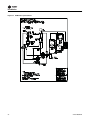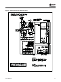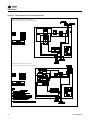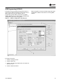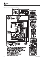
1
Installation, Operation, and Maintenance VariTrane™ Round Inlet/Round Outlet (VRRF) Models VRRF 04-16 SAFETY WARNING Only qualified personnel should install and service the equipment. The installation, starting up, and servicing of heating, ventilating, and airconditioning equipment can be hazardous and requires specific knowledge and training. Improperly installed, adjusted or altered equipment by an unqualified person could result in death or serious injury. When working on the equipment, observe all precautions in the literature and on the tags, stickers, and labels that are attached to the equipment. October 2013 VAV-SVN09B-EN Warnings, Cautions and Notices Warnings, Cautions and Notices. Note that warnings, cautions and notices appear at appropriate intervals throughout this manual. Warnings are provide to alert installing contractors to potential hazards that could result in death or personal injury. Cautions are designed to alert personnel to hazardous situations that could result in personal injury, while notices indicate a situation that could result in equipment or property-damage-only accidents. Your personal safety and the proper operation of this machine depend upon the strict observance of these precautions. Read this manual thoroughly before operating or servicing this unit. ATTENTION: Warnings, Cautions and Notices appear at appropriate sections throughout this literature. Read these carefully: Indicates a potentially hazardous situation which, if not avoided, could result in death or serious injury. Indicates a potentially hazardous CAUTIONs situation which, if not avoided, could result in minor or moderate injury. It could also be used to alert against unsafe practices. a situation that could result in NOTICE: Indicates equipment or property-damage only WARNING must also be adhered to for responsible management of refrigerants. Know the applicable laws and follow them. WARNING Proper Field Wiring and Grounding Required! All field wiring MUST be performed by qualified personnel. Improperly installed and grounded field wiring poses FIRE and ELECTROCUTION hazards. To avoid these hazards, you MUST follow requirements for field wiring installation and grounding as described in NEC and your local/state electrical codes. Failure to follow code could result in death or serious injury. WARNING Personal Protective Equipment (PPE) Required! Installing/servicing this unit could result in exposure to electrical, mechanical and chemical hazards. • Before installing/servicing this unit, technicians MUST put on all Personal Protective Equipment (PPE) recommended for the work being undertaken. ALWAYS refer to appropriate MSDS sheets and OSHA guidelines for proper PPE. • When working with or around hazardous chemicals, ALWAYS refer to the appropriate MSDS sheets and OSHA guidelines for information on allowable personal exposure levels, proper respiratory protection and handling recommendations. • If there is a risk of arc or flash, technicians MUST put on all Personal Protective Equipment (PPE) in accordance with NFPA 70E or other country-specific requirements for arc flash protection, PRIOR to servicing the unit. Important Environmental Concerns! Scientific research has shown that certain man-made chemicals can affect the earth’s naturally occurring stratospheric ozone layer when released to the atmosphere. In particular, several of the identified chemicals that may affect the ozone layer are refrigerants that contain Chlorine, Fluorine and Carbon (CFCs) and those containing Hydrogen, Chlorine, Fluorine and Carbon (HCFCs). Not all refrigerants containing these compounds have the same potential impact to the environment.Trane advocates the responsible handling of all refrigerants-including industry replacements for CFCs such as HCFCs and HFCs. Failure to follow recommendations could result in death or serious injury. Revision Summary VAV-SVN09B-EN Added UC400 and UC210 control information. Responsible Refrigerant Practices! Trane believes that responsible refrigerant practices are important to the environment, our customers, and the air conditioning industry. All technicians who handle refrigerants must be certified.The Federal Clean Air Act (Section 608) sets forth the requirements for handling, reclaiming, recovering and recycling of certain refrigerants and the equipment that is used in these service procedures. In addition, some states or municipalities may have additional requirements that © 2013Trane All rights reserved Trademarks Trane, VariTrane, VariTrac, Rover,Tracer Summit,Tracer SC,TracerTU and theTrane logo are trademarks ofTrane in the United States and other countries. All trademarks referenced in this document are the trademarks of their respective owners. VAV-SVN09B-EN Table of Contents Warnings, Cautions and Notices . . . . . . . . . . 2 Single Duct Hot Water . . . . . . . . . . . . . . . .23 Revision Summary . . . . . . . . . . . . . . . . . . . 2 Analog and DDC Fan Powered: Fan control . . . . . . . . . . . . . . . . . . . . . . . . .23 Trademarks . . . . . . . . . . . . . . . . . . . . . . . . . 2 Model Number Descriptions . . . . . . . . . . . . . . 4 General Information . . . . . . . . . . . . . . . . . . . . . Receiving and Handling . . . . . . . . . . . . . . . . Unit Information . . . . . . . . . . . . . . . . . . . . . . . Agency Listings Compliance . . . . . . . . . . . . 5 Analog Fan-Powered: Duct Pressure Switch only Fan Control . .23 5 Analog and DDC Fan-Powered: Fan-Powered Electric Heat . . . . . . . . . . . .25 5 Analog and DDC Fan Powered: Hot Water 25 5 UCM Programming (UCM 4.2) . . . . . . . . .29 Installation . . . . . . . . . . . . . . . . . . . . . . . . . . . . . . 6 UCM VV550 . . . . . . . . . . . . . . . . . . . . . . . . .33 Unit Accessibility . . . . . . . . . . . . . . . . . . . . 8 UC400 and UC210 . . . . . . . . . . . . . . . . . . .37 Clearances . . . . . . . . . . . . . . . . . . . . . . . . . . 8 Actuator Mounting . . . . . . . . . . . . . . . . . . .44 Duct Connections Installation . . . . . . . . . . 8 Wiring . . . . . . . . . . . . . . . . . . . . . . . . . . . . . . . . . .47 Installation Option Original Ductwork . . . . . . . . . . . . . . . . . . 10 Existing Installation Wrap-Up . . . . . . . . . 10 New Facility VRRF Installation (Non-Retrofit) . . . . . . . . . . . . . . . . . . . . . . 11 Specifications . . . . . . . . . . . . . . . . . . . . . . 11 Electrical Connections . . . . . . . . . . . . . . . 14 Power Wiring and Requirements . . . . . . . 14 Zone Sensor Wiring . . . . . . . . . . . . . . . . . 15 Auxiliary Duct Temperature Sensor . . . . 15 Stand Alone VAV Controls . . . . . . . . . . . . 15 Communication Link Wiring UCM 4.2 . . . . . . . . . . . . . . . . . . . . . . . . . . . 16 Communication Link Wiring UCM VV550 . . . . . . . . . . . . . . . . . . . . . . . . 17 Pneumatic units: Single Duct Electric Heat . . . . . . . . . . . . . 18 Pneumatic Units: Single Duct Hot Water . . . . . . . . . . . . . . . 22 Pneumatic Fan-Powered: Duct Pressure Switch Only Fan Control . 22 Pneumatic Fan-Powered: PE Switch Fan Control . . . . . . . . . . . . . . . 22 Pneumatic Fan-Powered: Electric Heat . . . . . . . . . . . . . . . . . . . . . . . 22 Pneumatic Fan Powered: Hot Water . . . . . . . . . . . . . . . . . . . . . . . . . 22 Analog and DDC Units: Single Duct Electric Heat . . . . . . . . . . . . . 23 Analog and DDC Units: VAV-SVN09B-EN 3 Model Number Descriptions V R R F 0 8 A 0 D D 0 4 5 W W H 1 D W 0 F W C 0 1 2 3 4 5 6 7 8 9 10 11 12 13 14 15 16 17 18 19 20 21 22 23 24 Digits 1-4— Unit Type VRRF= VariTrane™ Round Inlet and Outlet (Retrofit) Digit 5, 6—Primary Air Valve 04 05 06 08 10 12 14 16 = = = = = = = = 4" inlet (225 cfm) 5" inlet (350 cfm) 6" inlet (500 cfm) 8" inlet (900 cfm) 10" inlet (1400 cfm) 12" inlet (2000 cfm) 14" inlet (3000 cfm 16" inlet (4000 cfm) Digits 7, 8—Design Sequence ** = Factory assigned Digits 9-12—Unit Controls ENCL = Shaft only in enclosure DD00= Trane actuator only DD01= Cooling only control DD02= N.C. on/off hot water DD03= Prop hot water DD04= Stagged on/off e-heat DD05= Pulse-width modulation of e-heat DD07= N.O. on/off hot water DD11= VV550 DDC Controller— Cooling only DD12= VV550 DDC Controller w/ N.C. on/off HW valve DD13= VV550 DDC Controller w/ prop HW valve DD14= VV550 DDC Controller–on/ off electric heat DD15= VV550 DDC Controller w/ pulse-width modulation DD16= VV550 DDC Controller ventilation flow DD17= VV550 DDC Controller w/ N.O. on/off HW valve DD19= VV550 DDC Controller w/flow tracking DD20= VV550 DDC-vent flow w/N.C. on/off valve DD21= VV550 DDC-vent flow w/ on/off electric heat DD22= VV550 DDC-vent flow w/prop HW Valve DD33= VV550 DDC-vent flow w/ N.O. on/off valve DD41= UC400 DDC -Basic (Cooling only) DD42= UC400 DDC - Basic (Water heat - N.C. 2pos) DD43= UC400 DDC - Basic (Water heat - modulating) DD44= UC400 DDC - Basic (Electric heat - staged) DD45= UC400 DDC - Basic (Electric heat - pwm) DD46= UC400 DDC - Ventilation flow (No reheat) DD47= UC400 DDC - Basic (Water heat - N.O. 2pos) DD49= UC400 DDC - FlowTrack (Cooling only) DD50= UC400 DDC-Ventilation flow (N.C. 2pos) 4 DD51= UC400 DDC - Ventilation flow (Electric heat - staged) DD52= UC400 DDC - Ventilation flow (Water heat - modulating) DD63= UC400 DDC-Ventilation flow (Water heat - N.O. 2pos) DD71= UC210 DDC-Basic (Cooling only) DD72= UC210 DDC-Basic (Water heatN.C.- 2 position) DD73= UC400 DDC-Basic (Water heatModulating) DD74= UC210 DDC-Basic (Electric heatstaged) DD75= UC210 DDC-Basic (Electric heatPWM) DD76= UC210 DDC Ventilation flowno reheat DD77= UC210 DDC-Basic (Water heatN.O.- 2 position) DD79= UC210 DDC-FlowTracking (Cooling only) DD80= UC210 DDC-Ventilation Flow (N. C.- 2 position) DD81= UC210 DDC-Ventilation Flow (Electric heat- staged) DD82= UC210 DDC-Ventilation Flow (Water heat- Modulating) DD93= UC210-Ventilation Flow (Water heat- N.O. 2-position) Notes: • N.C. = Normally-closed N.O. = Normally-opened Digit 13—Transformer 0 1 2 3 4 5 6 7 8 = = = = = = = = = None 120/24 volt (50 VA) 208/24 volt (50 VA) 240/24 volt (50 VA) 277/24 volt (50 VA) 480/24 volt (50 VA) 347/24 volt (50 VA) 575/24 volt (50 VA) 380/24 volt (50 VA) Digit 14—Disconnect Switch 0 = None W = With Note: Toggle Disconnect Digit 18—Outlet Adapters 0 C D = = = None Adapter (C Style) Adapter (D or E Style) Digit 19—Relay Kit(s) 0 = W = None With Digit 20—Water Valve 0 E F G H J K L = = = = = = = = None 2-Position, HW Valve, 4.0 Cv 2-Position, HW Valve, 5.0 Cv 2-Position, HW Valve, 6.0 Cv Proportional, HW Valve, 0.7 Cv Proportional, HW Valve, 2.7 Cv Proportional, HW Valve, 6.6 Cv Proportional, HW Valve, 8.0 Cv Digit 21—Zone Sensor 0 A B C D = = = = = E F = = G = H J K = = = None DDC Sensor Only DDC Sensor, ext. adj., comm jack DDC Sensor, nsb, comm jack DDC Sensor, ext. adj., nsb, comm jack Digital Display Zone Sensor Wireless-DDC Sensor, ext. adj., on/cancel, °F Wireless-DDC Sensor, ext. adj., on/cancel, °C Wireless-DDC Sensor ONLY, °F Wireless-DDC Sensor ONLY, °C Wireless-digital display sensor Digit 22—Factory Installed Solution 0 1 2 3 = = = = None With DuctTemperature Sensor HW Valve Harness DTS & H@ Valve Harness Digit 23—Actuator 0 A B = = = None Standard Belimo Digit 24—Special Options 0 S = = None Special Options Digit 15—Power Fuse 0 = W = None With Digit 16—Unit Orientation H V = = Horizontal Airflow Vertical Airflow (up or down) Digit 17—Wireless Sensor Options 0 1 2 = = = None (Standard) Wireless Wireless Communication Interface Modular FM VAV-SVN09B-EN General Information This manual describes the installation of the Round In Round out (VRRF) VAV units with mounting and recommended wiring of the VRRF units. • For controls setup and operation parameters, reference the following literature: Upon receiving the equipment, please inspect each unit and components for external or internal damage. Refer to the bill of lading to insure all equipment and accessories have been received. Contact your localTrane sales representative and notify the trucking company immediately of any short ship or damaged equipment. • UCM 4.2: VAV-SVX01*-EN • VV550: CNT-SVX17*-EN • UC400: VAV-SVX07*-EN • UC210: BAS-SVX62*-EN The VRRF can be used in new installations as well as retrofitting older style units. Note: Not all older-styleTrane VAV units can be retrofitted with the VRRF and should be researched before ordering the VRRF on a caseby-case basis. The VRRF can be ordered with or without DDC controls. If ordered with controls, the unit would have either a UCM 4.2, VV550 or UC400/UC210 DDC control module. The controls will be factory mounted to the RIRO damper and field installed to existing system. How this installation takes place will be dependent on if it is a new installation or if the unit is being retrofitted to a pre-existing unit type. Receiving and Handling The unit may be shipped from the factory in a number of different ways. Upon receiving the equipment, complete the following: • Locate the nameplate and refer to the model and sales order number and check that the correct units have been delivered. • Check that the facility can provide the correct voltage to the unit according to the name plate. • Inspect the control enclosure if applicable and the air damper casing for dents or punctures. • Verify the options have been included, such as controls, water valve, adapters, and relays kits which include wiring harnesses. • Manually rotate the damper actuator to assure that there are no obstructions within the housing. • Claims for in-transit damage must be filed immediately with the delivery carrier. • Locate and verify that the correct zone sensors are with the order.These will be marked with an orange “Accessories Enclosed” label. Store in a secure location until needed. Accessories lost at the jobsite are NOT covered byTrane’s warranty. • If a discrepancy occurs between what was ordered and what is received, contact you localTrane representative immediately. VAV-SVN09B-EN Read the appropriate section in this manual for installation procedures prior to actual starting of equipment. Unit Information The basic unit consists of a sheet metal casing with an air damper which is used to modulate the air being delivered into the occupied zone.The unit is designed to modulate either cooling or heating air between the temperatures of 40 and 140 degrees F. Primary air enters the air valve through its round inlet and sent into the air valve cylinder and exits from the round outlet.This air could be sent strait to the diffusers or in conjunction with a VAV unit that is being retrofitted. The basic unit can be ordered for vertical or horizontal airflow.The options for a basic unit that are available are power fuse, transformer, disconnect, adapter, DDC controller, and Wireless Zone sensor. Other options available if retrofitting electric heat or hot water units would be relay kits to support the control of electric heat strips.We can also include two-position or modulating hot water valves for control of hot water in the reheat coil. When looking to retrofit a fan powered unit, you could also order the relay kit(s) with the wiring harness as an option. All types of DDC controllers for theVRRF have 24VAC triac outputs.The UC400 and UC210 also have relay-based binary outputs.The outputs are available for retrofitting a single duct or a fan-powered unit. A single-duct unit could use the outputs available to control three (3) stages of electric heat, modulating hot water valve or two position hot water valve. For a fan-powered unit, the controller would use one output for the fan and the other two to control two stages of electric heat. If it had a hot water coil, then the two extra outputs could be used to control a modulating hot water valve or a two-position hot water valve.These re-heat units are used primarily to reheat airto-zone temperature when the load in the occupied space is low. Primary air is modulated through the VariTrane™ air valve by rotating the damper blade. All air valves have a round inlet for easy fit-up with incoming ductwork. Agency Listings Compliance • UL listed • AHRI 880 certified 5 Installation Due to their weight and size, VRRF units should be suspended from the uppermost ceiling, independent of the false ceiling grid. Suspension devices are to be supplied by the installer. Units must be installed level in the vertical or horizontal position.To check if the unit is a vertical or horizontal unit, look at the model number of the unit as compared to the Service Model Number Description in this installation guide. Figure 1. 6 Note: A VRRF unit that was ordered as a vertical unit must be in the vertical position and if it was ordered as a horizontal airflow unit, then it must be installed horizontal. Incorrect installation would void the warranty on the unit. Round in/round out common installation options VAV-SVN09B-EN Installation Figure 2. Round in/round out weights and sizes VAV-SVN09B-EN 7 Installation Table 1. recommended that 6" of top and bottom clearance be provided. C, D, or E style units(a) Controls Air Valve Type Outlet Connection Type Pneumatic Normally Closed Single Duct Elec. Heat Retrofit not possible(b) Pneumatic Normally Closed Parallel Fan Elec. Heat Retrofit not possible(b) Pneumatic Normally Closed All Others 1 Pneumatic Normally Open Single Duct Elec. Heat 2 Pneumatic Normally Open Parallel Fan Elec. Heat 2 Pneumatic Normally Open All Others 1&2 Analog Normally Open Single Duct Elec. Heat 2 Analog Normally Open Parallel Fan Elec. Heat 2 Analog Normally Open All Others 1&2 DDC Normally Open Single Duct Elec. Heat 2 DDC Normally Open Parallel Fan Elec. Heat 2 DDC Normally Open All Others 1&2 Notes: 1. Adapter design (Remove Old Air Valve and replace with Adapter for RIRO) 2. Standard RIRO unit (Drive valve to max. and install RIRO upstream of unit.) (a) C, D, E digit is found in the 4th digit of model number (b) When retrofit not possible, replace the existing unit. The minimum clearance for the controls is 36". NEC and/or local codes overrides all clearance requirements. Duct Connections Installation WARNING Hazardous Voltage! Disconnect all electric power, including remote disconnects before servicing. Follow proper lockout/ tagout procedures to ensure the power can not be inadvertently energized. Failure to disconnect power before servicing could result in death or serious injury. WARNING Heavy Objects! Ensure that all the lifting equipment used is properly rated for the weight of the unit being lifted. Each of the cables (chains or slings), hooks, and shackles used to lift the unit must be capable of supporting the entire weight of the unit. Lifting cables (chains or slings) may not be of the same length. Adjust as necessary for even unit lift. Other lifting arrangements could cause equipment or property damage. Failure to follow instructions above or properly lift unit could result in unit dropping and possibly crushing operator/ technician which could result in death or serious injury. WARNING Table 2. Fiberglass Wool! F style units(a) Controls Air Valve Type Outlet Connection Type Pneumatic Normally Closed All 2 Analog Normally Open All 2 DDC Normally Open All 2 Notes: 1. Standard RIRO unit (Drive valve to max. and install RIRO upstream of unit.) (a) F digit is found in the 4th digit of model number No hanger brackets are provided on these units since the unit should be supported by means of a hanger strap.The hanger strap should be secured to the unit casing as shown in Figure 1, p. 6. Unit Accessibility VRRF does not provide internal access, as all functioning components are external to the unit. Clearances For proper service it is recommended that 36" side clearance be provided for service and access. It is also 8 Product contains fiberglass wool. Disturbing the insulation in this product during installation, maintenance or repair will expose you to airborne particles of glass wool fibers and ceramic fibers known to the state of California to cause cancer through inhalation. You MUST wear all necessary Personal Protective Equipment (PPE) including gloves, eye protection, mask, long sleeves and pants when working with products containing fiberglass wool. Exposition to glass wool fibers without all necessary PPE equipment could result in cancer, respiratory, skin or eye irritation, which could result in death or serious injury. All VRRF units should have a minimum of 1.5 duct diameters of straight duct prior to the inlet of the VRRF. This is to allow accurate reading from the flow ring.The outlet connection is dependent on a number of factors. The main factor is your application. If the VRRF is used as a new installation, then you connect the outlet of theVRRF to the ductwork. If it is a retrofit of an existing unit, then it depends upon what type of unit you are looking to replace. (Table 1and Table 2 show the different styles of units and the possible outlet connection. When determining which of these two tables to use, reference the fourth digit in Model Number of the existing VAV unit.) VAV-SVN09B-EN Installation When installing the VRRF to a pre- existing unit, remove power from pre-existing unit and lock and tag out unit. Remove or pull back insulation and remove the amount of inlet ductwork necessary to install the RIRO damper. (See Figure 2, p. 7 for VRRF lengths.) 6. Remove air valve from existing VAV unit by breaking the seal around air inlet and the VAV unit. Once it is loose, remove air valve. (See Figure 5) Figure 5. Remove air valve Note: Make sure existing VAV unit and inlet ductwork is adequately supported before removing the section of ductwork necessary to install VRRF. Adaptor Option Installation 1. Ensure power has been removed from pre-existing unit and it has been locked and tagged out. 2. If not already done, begin removing insulation from the primary air inlet of pre-existing VAV unit. 3. On electric air valves, remove plug connection from J1 terminal and cut plug off of wire and feed wiring from the control enclosure into the existing unit (See Figure 3). Figure 3. Remove plug connection 7. Clean the surface on existing VAV unit where the air valve connected to existing VAV unit. Place new sealant around adapter mounting flange. 8. Mount adapter plate to the existing VAV unit by aliening the adapter to the proper hole pattern on the existing VAV unit and screwing in screws. Make sure that the adaptor is also mounted with hole pattern so that the VRRF controller is level to the ground. (See Figure 6) Figure 6. Adapter mounting Note: Both the control enclosure and existing unit has a grommet that may need to be removed to get wire into existing VAV unit. 4. On pneumatic air valves, remove pneumatic tubing from air valve. Note: Be aware, on a limited number of units the pneumatic air valve was too large to remove from inlet and the hole unit would have to be taken down to remove the air valve. 5. Remove self tapping screws from air inlet mounting bracket. In addition, remove pneumatic tubing from airflow ring. (See Figure 4) Figure 4. Remove pneumatic tubing 9. Seal around flange of adapter with duct sealant. 10. Install the Round In / Round Out (VRRF) VAV unit into adapter making sure control box is level and hang straps to support VRRF. (See Figure 1, p. 6 for Installation and Figure 2, p. 7 for weights) 11. Attach VRRF air valve cylinder to adapter plate using self-tapping screws. 12. Seal around flange of adapter with duct sealant. 13. Connect inlet ductwork to VRRF and screw in self tapping screws. 14. Seal around flange of ductwork and VRRF with duct sealant. Note: When retrofitting single duct units with electric heat and series Fan powered pneumatic electric heat units, the electric heat airflow switch has to have its input removed from existing air valve and connected to the new VRRF.This is done by VAV-SVN09B-EN 9 Installation removing the old tubing from the airflow switch and using the black tubing provided in the adaptor kit. Connect the airflow switch to the high pressure port of the VRRF unit.There is a tee located in the VRRF unit control box for this. Installation Option Original Ductwork 1. Make sure the existing VAV unit has its air valve set to the open position allowing airflow.With a DDC unit this can be done with Summit (BMTW-SVN01*-EN), Rover™ (EMTX-SVX01*-EN).The analog unit can have the damper driven open by removing the pneumatic tubing from the flow ring and adjusting the analog sensor thumbwheel to its lowest possible setting. See programming guide for your particular access tool. With a pneumatic system, you would release the actuator pressure inlet and cap pneumatic tubing.This will open the Normally Open Valve and allow airflow. 2. Ensure power has been removed from pre-existing unit and it has been locked and tagged out. WARNING Heavy Objects! Ensure that all the lifting equipment used is properly rated for the weight of the unit being lifted. Each of the cables (chains or slings), hooks, and shackles used to lift the unit must be capable of supporting the entire weight of the unit. Lifting cables (chains or slings) may not be of the same length. Adjust as necessary for even unit lift. Other lifting arrangements could cause equipment or property damage. Failure to follow instructions above or properly lift unit could result in unit dropping and possibly crushing operator/ technician which could result in death or serious injury. 5. Connect inlet ductwork to VRRF and screw in self tapping screws. 6. Seal around flange of ductwork and VRRF with duct sealent. 7. Connect outlet ductwork to VRRF and screw in self tapping screws. WARNING Hazardous Voltage! 8. Seal around flange of ductwork and VRRF with duct sealent. Disconnect all electric power, including remote disconnects before servicing. Follow proper lockout/ tagout procedures to ensure the power can not be inadvertently energized. Failure to disconnect power before servicing could result in death or serious injury. Existing Installation Wrap-Up 3. If not already done, begin removing about four inches of insulation from the ductwork where the inlet and outlet of the Round In / Round Out (VRRF) will connect. Note: Do not disconnect flow ring tubing. It may need to stay attached for proper VRRF unit operation. 1. After all connections are made (for either using the adapter or original ductwork), check to ensure the entire ductwork is air tight. Apply duct sealer as necessary. 2. Cut to specifications on your unit, as shown in Figure 8, p. 11 and Table 3, p. 11. Cut “slits” in the insulation for the flow tubes and brackets. Secure with duct tape. Encase VRRF with insulation. See Figure 7, p. 10. Figure 7. VRRF insulation WARNING Fiberglass Wool! Product contains fiberglass wool. Disturbing the insulation in this product during installation, maintenance or repair will expose you to airborne particles of glass wool fibers and ceramic fibers known to the state of California to cause cancer through inhalation. You MUST wear all necessary Personal Protective Equipment (PPE) including gloves, eye protection, mask, long sleeves and pants when working with products containing fiberglass wool. Exposition to glass wool fibers without all necessary PPE equipment could result in cancer, respiratory, skin or eye irritation, which could result in death or serious injury. 4. 10 3. Use care not to damage the flow tubes when making ductwork connections or insulating. Hang the VRRF with straps (See Figure 1 for Install and Figure 2 for weights) VAV-SVN09B-EN Installation New Facility VRRF Installation (Non-Retrofit) Table 3. Note: When installing VRRF, make sure the controller is level so the transducer can read airflow accurately. Important: Make sure inlet and outlet ductwork are adequately supported before installing VRRF. 1. Before hanging VRRF, ensure that the VRRF will have a minimum of 1.5 duct diameters of strait duct prior to the inlet of the VRRF. Insulation for RIRO A B C 12" 41.5 28 16.5 8 17 19.5 14" 47.5 32.75 18.25 9.5 17 19.5 16" 56 35.5 18.75 9.25 17 19.5 Figure 8. D Length Length w/o w/ adapter adapter Insulation cut measurements 2. Hang theVRRF with straps (See Figure 1, p. 6 for Install and Figure 2, p. 7 for weights) WARNING Heavy Objects! Ensure that all the lifting equipment used is properly rated for the weight of the unit being lifted. Each of the cables (chains or slings), hooks, and shackles used to lift the unit must be capable of supporting the entire weight of the unit. Lifting cables (chains or slings) may not be of the same length. Adjust as necessary for even unit lift. Other lifting arrangements could cause equipment or property damage. Failure to follow instructions above or properly lift unit could result in unit dropping and possibly crushing operator/ technician which could result in death or serious injury. Specifications 3. Connect inlet ductwork to VRRF and screw in self tapping screws. UCM 4.2 4. Seal around flange of ductwork and VRRF with duct sealant. Power Requirements Supply: 18-32 VAC (24VAC nominal) at 50/60 Hz 5. Connect outlet ductwork to VRRF and screw in self tapping screws. Operating EnvironmentTemperature: 32 to 140 F (0-60 C) Relative Humidity 10 to 90% non-condensing 6. Seal around flange of ductwork and VRRF with duct sealant. 7. After all connections are made , check to insure the entire ductwork is air tight. Apply duct sealer as necessary. 8. Cut to specifications on your unit, as shown in Figure 8 and Table 3. Cut “slits” in the insulation for the flow tubes and brackets. Secure with duct tape. Encase VRRF with insulation. See Figure 7. 9. Use care not to damage the flow tubes when making ductwork connections or insulating. Table 3. Insulation for RIRO Length Length w/o w/ adapter adapter A B C D 4" 21.5 16.75 10.75 5.25 17 19.5 5" 21.5 16.75 10.75 5.25 17 19.5 6" 21.5 16.75 10.75 5.25 17 19.5 8" 29.5 21.5 12.75 6.5 17 19.5 10" 36 25 15.75 7.5 17 19.5 VAV-SVN09B-EN Storage EnvironmentTemperature: -40 to 150 F Relative Humidity 10 to 90% non- condensing Analog inputs Space temperature Thermistor 10 K ohms @77 F(25 C) From 14 to 122 F (-10 to 50 C) Space setpoint Potentiometer 1K ohms From 50 to 90 F (10 to 32.2 C) Primary discharge air temperature 10 K ohms @77 F(25 C) From -40 to 212 F (-40 to 100 C) Primary airflow Transducer 0-2in. water (0 to 498 Pa) 11 Installation Binary input occupancy or generic (dry contact) Binary outputs Air valve open Maximum output rating forTriac: 12VA Air valve close Maximum output rating forTriac: 12VA Heat stage 1: Maximum output rating forTriac: 12VA Heat stage 2: Maximum output rating forTriac: 12VA Heat stage 3 or Fan output: Maximum output rating forTriac: 12VA UC400 Table 4. Storage Temperature: –48°F to 203°F (–44°C to 95°C) Relative Humidity: Between 5% and 95% (non-condensing) Operating Temperature: –40°F to 185°F (–40°C to 70°C) Humidity: Between 5% and 95% (non-condensing) Input Voltage: Environmental NEMA 1 rating (enclosure): Power Requirements Supply: 18-32 VAC (24VAC nominal) at 50/60 Hz Altitude: 9,842 ft. maximum (3,000 m) Installation: U.L. 840: Category 3 Operating EnvironmentTemperature: 32 to 140 F (0-60 C) Relative Humidity 5 to 95% non- condensing Pollution: U.L. 840: Degree2 Polycarbonate/ABS Blend Housing Material: UV protected U.L. 94-5VA flammability rating Mounts on EN 50 022 - 35 X 15 DIN rail that is Mounting: included in the VAV unit control box when the UC400 is factory mounted. Storage EnvironmentTemperature: -40 to 185 F Relative Humidity 5 to 95% non- condensing Space setpoint Potentiometer 1K ohms From 50 to 90 F (10 to 32.2 C) Primary discharge air temperature 10 K ohms @77 F(25 C) From -40 to 212 F (-40 to 100 C) Primary airflow Transducer 0-2in. water (0 to 498 Pa) 20.4–27.6 Vac (24, ±15% nominal), 50Hz to 60Hz Mounting weight of Mounting surface must support 0.80 lb. (.364 kg) controller: UCM VV550 Analog inputs Space temperature Thermistor 10 K ohms @77 F(25 C) From 14 to 122 F (-10 to 50 C) UC400 specifications Agency Listing/Compliance • • • • • • • • UL916 PAZX, Open Energy Management Equipment UL94-5V, Flammability CE Marked FCC Part 15, Subpart B, Class B Limit AS/NZS CISPR 22:2006 VCCI V-3/2008.04 ICES-003, Issue 4:2004 Communications BACnet MS/TP, supports BACnet protocol ASHRAE 135-2004 and meets BACnet Testing Laboratory (BTL) as an Application Specific Controller (ASC) profile device UL864/UUKL listed when installed and programmed in accordance with the Trane Applications Guide, BAS-APG019-EN. Device Inputs/Outputs Below is a list of device inputs and outputs. • A twisted/shielded communication link Binary input occupancy or generic (dry contact) • Zone sensor • Occupancy sensor (optional) Binary outputs • Discharge AirTemperature (DAT) and/or Supply Air Temperature (SAT) • CO2 sensor • 24 Vac, Class II power Air valve open Maximum output rating forTriac: 12VA Air valve close Maximum output rating forTriac: 12VA Heat stage 1: Maximum output rating forTriac: 12VA Heat stage 2: Maximum output rating forTriac: 12VA Heat stage 3 or Fan output: Maximum output rating forTriac: 12VA 12 In addition to the points used for the VAV application, the spare inputs and outputs on the UC400 controller may be used for ancillary control and programmed usingTracer TUTracer Graphical Programming 2 (TGP2). Note: For more information on wiring spare points, refer to theTracer UC400 Programmable Controller Installation, Operation, and Maintenance Manual (BAS-SVX20). VAV-SVN09B-EN Installation Analog Inputs Binary Outputs • Binary Outputs Type Output Rating BO1 Fan 10A up to 277 Vac 10A at 30 Vac/VDC, 2A at 120 Vac, 8 A at 250 Vac BO2 Spare Relay 10A up to 277 Vac 10A at 30 Vac/VDC, 2A at 120 Vac, 8 A at 250 Vac BO3 Spare Relay 10A up to 277 Vac • Range: from 50°F to 90°F (10°C to 32.2°C), */** (thumbwheel) functionality supported 10A at 30 Vac/VDC, 2A at 120 Vac, 8 A at 250 Vac BO4 Fan ON/Off 24-27 Vac, 0.5A Resistive VA AI3 BO5 Heat stage 3 TRIAC 24-27 Vac, 0.5A Resistive VA BO6 Heat stage 2/Water Valve Close TRIAC 24-27 Vac, 0.5A Resistive VA • Discharge air temperature: 10k @77°F (25°C) BO7 Heat stage 1/Water Valve Open TRIAC 24-27 Vac, 0.5A Resistive VA • Range: from -40°F to 212°F (-40°C to 100°C) BO8 Air Damper Close TRIAC 24-27 Vac, 0.5A Resistive VA AI5 BO9 Air Damper Open TRIAC 24-27 Vac, 0.5A Resistive VA AI1 • Space temperature; thermistor: 10k @77°F (25°C) • Range: 32°F to 122°F (0°C to 50°C) • AI2 • Space setpoint; potentiometer: 1k • • Spare • • AI4 • Supply air temperature: 10k @77°F (25°C) • Range: from -40°F to 212°F (-40°C to 100°C) Universal Inputs • Analog Outputs • • Spare output. • Spare, but recommended for relative humidity • Voltage output is 0 to 10 Vdc, 500 minimum impedance. • Current output is 4-20 mA, 500 max. impedance. • Also can output 100 Hz PWM signal for control of a Trane fan-powered ECM fan setpoint signal to the EC motor. • Current Mode Impedance: 200 , Voltage Mode Impedance: 10k minimum UI2; • Provided point for CO2 • Resistive/thermistor inputs: 0-10 Vdc inputs or 4-20 mA inputs • Current Mode Impedance: 200 , Voltage Mode Impedance: 10k minimum Pressure Inputs • P1 • Supply airflow, pressure transducer • Voltage output is 0 to 10 Vdc, 500 minimum impedance. • Current output is 4-20 mA, 500 maximum impedance. • Also used onTrane VAV units for SCR electric heat 0-to-10 Vdc modulation control. UC210 BI1 BI2 • Spare • • Spare. • Spare (recommended for dual duct secondary airflow) • Occupancy • AO2 P2 Binary Inputs • • Note: For more information on wiring spare points, refer to theTracer UC400 Programmable Controller Installation, Operation, and Maintenance Manual (BAS-SVX20). • From 0 to 2 in. water column (0 to 498 Pa) • AO1 UI1; • Resistive/thermistor inputs: 0-10 Vdc inputs or 4-20 mA inputs • Pilot duty BI3 • Spare VAV-SVN09B-EN Table 5. UC400 specifications Storage Temperature: -40 to 185°F (-40 to 85°C) Humidity: 5% to 95% (non-condensing) Operating Temperature: -40 to 185°F (-40 to 85°C) Humidity: 5% to 95% (non-condensing) 20.4-27.6 Vac, (24 Vac± 15% nominal), 50-60 Input Voltage: Hz, 10.5 VA plus 1 VA per 20mA of 24 VDC load plus 12 VA maximum per binary load 13 Installation Table 5. UC400 specifications (continued) Environmental NEMA 1 rating (enclosure): Table 6. UC210 inputs and outputs (continued) • AO1: ECM • AO2: SCR Heat Installation: UL 840: Category 3 Pollution: UL 840: Degree 2 Agency Listing/Compliance • • • • • • • • UL916 PAZX, Open Energy Management Equipment UL94-5V, Flammability CE Marked FCC Part 15, Subpart B, Class B Limit AS/NZS CISPR 22:2006 VCCI V-3/2008.04 ICES-003, Issue 4:2004 Communications BACnet MS/TP, supports BACnet protocol ASHRAE 135-2004 and meets BACnet Testing Laboratory (BTL) as an Application Specific Controller (ASC) profile device. • Suitable for Plenum mounting Device Inputs/Outputs • BO1: Heat stage 3 TRIAC • BO2: Heat stage 2/Water Valve Close TRIAC • BO3: Heat stage 1/Water Valve Open TRIAC • BO4: Air Damper Close TRIAC • BO5: Damper Open TRIAC Electrical Connections Wired sensor and for the wireless sensor BAS-SVX04*-EN Zone Sensor Wiring: Location and Mounting A zone sensor in each control zone should be located in the most critical area of the zone. Sensors should not be mounted in direct sunlight or in the area’s supply air stream. Subdivision of the zone may be necessary for adequate control and comfort. Below is a list of device inputs and outputs. Avoid mounting zone sensors in areas subject to the following: • Twisted/shielded communication link • Drafts or “dead spots” behind doors or corners. • Zone sensor • Hot or cold air ducts. • Occupancy sensor (optional) • Radiant heat from the sun or appliances. • Discharge AirTemperature (DAT) • Concealed pipes or chimneys. • CO2 sensor • • 24 Vac, Class II power Unheated or uncooled surfaces behind the sensor such as outside walls. • Air flows from adjacent zones or other units. Table 6 provides details for each type input/output. Power Wiring and Requirements Table 6. UC210 inputs and outputs Analog Input 1 through 3 Universal Inputs UI1 and UI2 Note: Configuration options when used as Note: Configuration options spare; 10 kΩ termistor, 0 to 1 kΩ when used as spare; linear setpoint, 200Ω to 20kΩ resistor/thermistor inputs, linear. 10 Vdc inputs, or 4-20 mA inputs. current mode impedance is 200Ω • AI1: Space temperature; • UI1: Relative Humidity thermistor: 10k @77°F (25°C) • UI2: CO2 range: 32°F to 122°F (0°C to 50°C) • AI2: Space setpoint; potentiometer: 1k from 50 to 90°F (10 to 32.2°C), */** (thumbwheel) functionality supported • AI3: Discharge air temperature: 10kΩ @77°F (25°C) from -40°F to 212°F (-40 to 100°C) Pressure Input P1 Binary Input BI1, Dry Contact • P1: Supply air flow; pressure transducer: From 0 to 2 in. water column (0 to 498 Pa) • BI1: Occupancy Analog Outputs AO1 and AO2 Binary Outputs 1 through 5 Note: Configuration options when used a Note: 0.5A Resistive Maximum spare; Voltage output is 0-10 Vdc, Rating 500Ω min. impedance. Current outpout is 4-20 mA, 500Ω max, impedance. 14 WARNING Hazardous Voltage! Disconnect all electric power, including remote disconnects before servicing. Follow proper lockout/ tagout procedures to ensure the power can not be inadvertently energized. Failure to disconnect power before servicing could result in death or serious injury. Use at least 16 AWG for power wiring and connect to terminalTB1-1 (+) andTB1-2 (-). 24 VAC is required to power the UCM control and has an acceptable voltage tolerance of 20 to 28 VAC on UCM 4.2 and 18 to 32 VAC on VV550. Replace the UCM control box cover after field wiring to prevent any electromagnetic interference. Note: A dedicated 24 VAC, 50VA NEC class 2 transformer is recommended to power the UCM. When powering multiple UCMs from one transformer, polarity must be maintained.TerminalTB1-1 is designated positive (+) and terminalTB1-2 is negative (-) to the unit casing ground. All wiring must comply with the National Electric Code (NEC) and local codes. Maximum wire lengths should be based on NEC specifications. VAV-SVN09B-EN Installation • Figure 44 and Figure 45 for the UCM 4.2 auxiliary sensor is not installed the UCM will retain the last control action in effect. • Figure 46 and Figure 47 for the VV550 Stand Alone VV550 • Figure 48 and Figure 49 for the UC400 • Figure 50 and Figure 51 for the UC210 When there is no communication to theVV550 control and the unit is in the stand alone mode the control action is determined by the auxiliary temperature sensor located onTB3-5 andTB3-6 terminals on the VV550 board.The control must also be configured through the “InputsTab” of Analog Input 4 as “Primary Supply Air Sensor”. In order for the auxiliary sensor to determine the control action (heat, cool) it must be located in the supply inlet of the duct.The auxiliary temperature is then compared to the zone temperature. If the supply air temperature is 10 degrees above the zone temperature, then the control action will be heat. If the supply air temperature is less than or equal to the zone temperature, then the control action will be cool. If the supply air temperature is between the zone temperature and the zone temperature + 10ºF (5.5°C)(zone temperature < supply air temperature < zone temperature + 10ºF) (5.5°C), the control action remains the same and the UCM controls to the minimum flow set point. If an auxiliary sensor is not installed the UCM will retain the last control action in effect. See Control Diagrams: Zone Sensor Wiring Each unit must be controlled by a zone sensor that is designated specifically for use with the UCM control. Field wiring for the zone sensors must meet the following requirements: • Must be 14 to 18 AWG. • Refer to the sensor instructions for terminal connections. • If local codes require enclosed conductors, the zone sensor wires should be installed in conduit. Do not route zone sensor wires in conduit with 24VAC or other high power conducting wires. • Cost of wiring labor can be reduced through the use of aTrane wireless zone sensor. It requires no wiring from the UCM to the zone sensor.The receiver will be powered and wired to the UCM when wireless sensor is ordered factory installed. Auxiliary Duct Temperature Sensor The typical mounting position of the auxiliary sensor is upstream of the VRRF unit and connected into the DDC controller atTB3-5 andTB3-6. Comm5 could be mounted downstream of the reheat for improved diagnostics. See Control Diagrams: • Figure 44 and Figure 45 for the UCM 4.2 • Figure 46 and Figure 47 for the VV550 • Figure 48 and Figure 49 for the UC400 • Figure 50 and Figure 51 for the UC210 Stand Alone VAV Controls Stand Alone UCM 4.2 When there is no communication to the UCM control and the unit is in the stand alone mode the control action is determined by the auxiliary temperature sensor located onTB3-5 andTB3-6 terminals on the UCM board. In order for the auxiliary sensor to determine the control action (heat, cool) it must be located in the supply duct.The auxiliary temperature is then compared to the zone temperature. If the supply air temperature is 10 degrees above the zone temperature, then the control action will be heat. If the supply air temperature is less than or equal to the zone temperature, then the control action will be cool. If the supply air temperature is between the zone temperature and the zone temperature + 10ºF (5.5°C)(zone temperature < supply air temperature < zone temperature + 10ºF) (5.5°C), the control action remains the same and the UCM controls to the minimum flow set point. If an VAV-SVN09B-EN Stand Alone UC400 When there is no communication to the UC400 control and the unit is in the stand alone mode the control action is determined by the auxiliary temperature sensor located on AI5 terminals on the UC400 control. Note that optional factory installed auxiliary temperature sensors are wired to AI4 for use as discharge temperature sensors. For these to be used as supply air temperature sensore, they need to be disconnected from AI4 and connected to AI5. If the unit has reheat, the supply air temperature sensor needs to be installed upstream of the VAV unit.The supply air temperature is then compared to the zone temperature. If the supply air temperature is 10 degrees above the zone temperature, then the control action will be heat. If the supply air temperature is less than or equal to the zone temperature, then the control action will be cool. If the supply air temperature is between the zone temperature and the zone temperature + 10ºF (5.5°C)(zone temperature < supply air temperature < zone temperature + 10ºF) (5.5°C), the control action remains the same and the UCM controls to the minimum flow set point. If an auxiliary sensor is not installed the UCM will retain the last control action in effect. Stand Alone UC210 When there is no communication to the UC210 control and the unit is in the stand alone mode the control action is determined by the auxiliary temperature sensor located on AI3 terminals on the UC210 control.The point configuration for AI3 is configured from the factory for discharge air temperature and would need to be reconfigured for supply air temperature usingTracerTU to remove the discharge air temperature AI3 hardware reference and to add the AI3 hardware reference to supply 15 Installation air temperature. In order for the auxiliary sensor to function as a supply air temperature sensor on VAV units with reheat and to properly determine the control action (heat, cool) it must be located upstream of the VAV unit. The auxiliary temperature is then compared to the zone temperature. If the supply air temperature is 10 degrees above the zone temperature, then the control action will be heat. If the supply air temperature is less than or equal to the zone temperature, then the control action will be cool. If the supply air temperature is between the zone temperature and the zone temperature + 10ºF (5.5°C)(zone temperature < supply air temperature < zone temperature + 10ºF) (5.5°C), the control action remains the same and the UCM controls to the minimum flow set point. If an auxiliary sensor is not installed the UCM will retain the last control action in effect. • Non-Plenum Cable: Stranded tinned copper insulated with polyethylene. Conductors cabled and shielded with overall aluminum/polyester tape and stranded, tinned copper drain wire. Chrome gray PVC jacket, 300 volt, 60°C NEC type CM, 24 pF/ft. Wire Capacitance Wire capacitance must comply with the following table: Table 7. Max. Communication Link Wiring Length Max. Wire Capacitance 1,000 feet (304.8m) Up to 60 pF/ft. (196.9 pF/m) Communication Link Wiring UCM 4.2 The “Communication Link” is the communication wiring betweenTracer Summit™ and all VAV box Unit Control Modules (UCM).Tracer Summit can be connected to the UCM communication link in a “daisy chain” configuration. Note: All wiring from the zone sensor to the Comm link must be twisted shielded pair wiring. The “Communication Link” is the communication wiring betweenTracer Summit and all VAV box Unit Control Modules (UCM).Tracer Summit can be connected to the UCM. Note: It is not necessary for each UCM to be connected to the line in sequential order by address. Also, multiple communication links may be run and terminated at theTracer Summit. However, a consistent, documented wiring path will help troubleshoot communication problems after installation. Field wiring for the communication link must meet the following requirements: 1. All wiring must be in accordance with the National Electrical code and local codes. 2. Communication link wiring must be at least 18 AWG twisted shielded pair wire. Shields must be grounded at theTracer Summit or Central Control Panel (CCP) only. More than one ground reference will cause communications failures. Shields must be daisy chained.Tape the shield at the lastVAV UCM to prevent any connection between the shield and ground. Plenum Cable and Non-Plenum Cable wire specifications are as follows: • Plenum Cable: Stranded, tinned copper insulated with extruded FEP. Conductors cabled and shielded with overall aluminum/Mylar tape and stranded, tinned copper drawn wire. Extruded jacket, 300 volt, 150°C NEC 725-2 (b) class 2, type CL2P, 25 pF/ft. 16 Max wire capacitance 2,000 feet (609.6 m) Up to 50 pF/ft. (164.0 pF/m) 3,000 feet (914.4m) Up to 40 pF/ft. (131.2 pF/m) 4,000 feet (1,219.2 m) Up to 30 pF/ft. (98.4 pF/m) 5,000 feet (1,524 m) Up to 25 pF/ft. (82.0 pF/m) 1. The maximum wire length should not exceed 5,000 feet (1,524 m). 2. Communication link wiring cannot pass between buildings. 3. A maximum of 63 UCMs can be connected to each COM Link. Daisy chaining is a typical configuration. 4. Polarity is extremely important and must be observed on communication link connections. 5. At the VAV box, communication link wires must be connected toTB2-1, 3 (+) andTB2-2, 4 (-) terminals on the UCM. 6. Verify that the UCM address is properly set (DIP switch SW1). See Table 7 for proper DIP switch settings. DIP Switch Settings DIP Switch SW1 contains six switches for addressing the UCM.These switches allow a user to set a unique communication address for each UCM. Each UCM on a given communication link must have a unique address in order forTracer Summit or the CCP to communicate to it. See Table 8 for UCM 4.2 DIP switch settings. Table 8. DIP switch settings UCM Unit # Eware Address 1 65 OFF ON ON ON ON ON 2 66 ON OFF ON ON ON ON 3 67 OFF OFF ON ON ON ON 4 68 ON ON OFF ON ON ON 5 69 OFF ON OFF ON ON ON 6 70 ON OFF OFF ON ON ON 7 71 OFF OFF OFF ON ON ON 8 72 ON ON ON OFF ON ON 9 73 OFF ON ON OFF ON ON 10 74 ON OFF ON OFF ON ON Dip 1 Dip 2 Dip 3 Dip 4 Dip 5 Dip 6 VAV-SVN09B-EN Installation Table 8. DIP switch settings (continued) Table 8. DIP switch settings (continued) UCM Unit # Eware Address Dip 6 UCM Unit # Eware Address 11 75 OFF OFF ON OFF 12 76 ON ON OFF OFF ON ON 58 122 ON OFF ON OFF OFF ON ON 59 123 OFF OFF ON OFF OFF 13 77 OFF ON OFF OFF OFF ON ON 60 124 ON ON OFF OFF OFF OFF 14 78 ON OFF OFF OFF ON ON 61 125 OFF ON OFF OFF OFF OFF 15 79 OFF OFF OFF OFF 16 80 ON ON ON ON ON ON 62 126 ON OFF OFF OFF OFF OFF OFF ON 63 127 OFF OFF OFF OFF OFF 17 81 OFF ON ON ON OFF ON OFF 18 82 ON OFF ON ON OFF ON 19 83 OFF OFF ON ON OFF ON Communication Link Wiring UCM VV550 20 84 ON ON OFF ON OFF ON Follow these guidelines for Comm5 wiring: 21 85 OFF ON OFF ON OFF ON • 22 86 ON OFF OFF ON OFF ON Use 22 AWG unshielded Level 4 communication wire for most Comm5 installations 23 87 OFF OFF OFF ON OFF ON • 24 88 ON ON ON OFF OFF ON Use shielded Level 4 wire for Comm5Tracker and VariTrac™ CCP installations 25 89 OFF ON ON OFF OFF ON • Always use termination resistors 26 90 ON OFF ON OFF OFF ON 27 91 OFF OFF ON OFF OFF ON • Use 105, watt, 1% resistor at each end for Level 4 wire 28 92 ON ON OFF OFF OFF ON • 29 93 OFF ON OFF OFF OFF ON Use 82.5, watt, 1% resistor at each end forTrane purple wire 30 94 ON OFF OFF OFF OFF ON • Use the daisy chain topology for Comm5 links 31 95 OFF OFF OFF OFF OFF ON • Limit the Comm5 link to 4500 feet Limit the link to 60 devices Dip 1 Dip 2 Dip 3 Dip 4 Dip 5 Dip 1 Dip 2 Dip 3 Dip 4 Dip 5 Dip 6 OFF ON ON ON ON OFF • OFF ON ON ON ON OFF • ON OFF ON ON ON OFF Limit zone sensor communication stubs to 8 per link, 50 feet each (maximum) 99 OFF OFF ON ON ON OFF • 100 ON ON OFF ON ON OFF Use one repeater for an additional 4500 feet, an additional 60 devices, and an additional 8 communication stubs 32 96 ON 33 97 34 98 35 36 37 101 OFF ON OFF ON ON OFF 38 102 ON OFF OFF ON ON OFF 39 103 OFF OFF OFF ON ON OFF 40 104 ON ON ON OFF ON OFF 41 105 OFF ON ON OFF ON OFF Daisy chain 42 106 ON OFF ON OFF ON OFF 43 107 OFF OFF ON OFF ON OFF 44 108 ON ON OFF OFF ON OFF 45 109 OFF ON OFF OFF ON OFF Although other topologies have been used in the past, we recommend using only the daisy chain topology on your Comm5 installations.The likelihood of communication problems increases with other configurations. 46 110 ON OFF OFF OFF ON OFF 47 111 OFF OFF OFF OFF ON OFF 48 112 ON ON ON ON OFF OFF 49 113 OFF ON ON ON OFF OFF 50 114 ON OFF ON ON OFF OFF 51 115 OFF OFF ON ON OFF OFF 52 116 ON ON OFF ON OFF OFF 53 117 OFF ON OFF ON OFF OFF 54 118 ON OFF OFF ON OFF OFF 55 119 OFF OFF OFF ON OFF OFF 56 120 ON ON ON OFF OFF OFF 57 121 OFF ON ON OFF OFF OFF VAV-SVN09B-EN Limit the distance of Comm5 links to 4500 feet. In addition, limit Comm5 links to 60 devices.The BCU, repeater, and Rover™ do not count toward this total. Zone sensor comm stubs For the most reliable communications, limit the number of zone sensor communication stubs to 8 per Comm5 link. Each stub should not exceed 50 feet. Exceeding these limits increases the likelihood of communication problems. Binary Outputs Wiring to air damper is factory installed but the outputs to reheat or fan control need to be field installed when applicable. Note: All field installed wiring must comply with NEC and local codes. 17 Installation All binary outputs from control board are 24 VAC. Connection points for unit UCM controller are shown in Control Diagrams: • All wiring must comply with the National Electrical Code™ (NEC) and local codes. • Ensure that 24 Vac power supplies are consistent in regards to grounding. Avoid sharing 24 Vac between controllers. • Avoid over tightening cable ties and other forms of cable wraps.This can damage the wires inside the cable. The type of wire used would be a Plenum rated class 2 circuit cable (CL2P) or approved substitute.The wire can be 18t o 22 gauge and be used at a distance of up to 100 ft. • Do not run communication cable alongside or in the same conduit as 24 Vac power.This includes the conductors running fromTRIAC-type inputs. VRRF DDC controller Power Wiring • In open plenums, avoid running wire near lighting ballasts, especially those using 277 Vac. • Use same communication wire type, without terminators, for the zone sensor communication stubs from the UC400 controller IMC terminals to the zone sensor communication module. • Zone Sensor communication wiring length limits of 300 ft. (100 m). • Figure 44 and Figure 45 for the UCM 4.2 • Figure 46 and Figure 47 for the VV550 • Figure 48 and Figure 49 for the UC400 • Figure 50 and Figure 51 for the UC210 In VRRF unit connect line voltage wires to optional transformer or Connect 24VAC toTB1-1 (+) andTB1-2 (-) Proper polarity must be maintained.TB1-1 is the hot side (+) andTB1-2 is the ground side (-) of the 24 VAC input.The UCM cannot be powered from a common 24 VAC transformer that is supplying power to a device containing a full wave rectifier bridge in its power supply.The acceptable voltage is 20 to 28 VAC (24 VAC cataloged). However, voltages at either extreme may result in increased system instability. Communication Link Wiring UC400 and UC210 • Use 18 AWGTrane purple-shielded communication wire for BACnet installations. • Link limit of 4,000 ft and 60 devices maximum (without a repeater). • Use aTrane BACnet termination on each end of the link. • Use daisy chain topology (See Figure 9). • Maintain polarity. Figure 9. Note: For more details, refer to the Unit ControllerWiring for theTracer SC™ System ControllerWiring Guide (BAS-SVN03). Pneumatic units: Single Duct Electric Heat Remove Power and Lock andTag out unit if it hasn't been done already. WARNING Hazardous Voltage! Disconnect all electric power, including remote disconnects before servicing. Follow proper lockout/ tagout procedures to ensure the power can not be inadvertently energized. Failure to disconnect power before servicing could result in death or serious injury. BACnet MS/TP link wiring 1. Disconnect PE switch(es) for each stage of heat from electric heat control enclosure and replace them with relay(s) from kit. BI LINK IM + VDC IMC BI LINK IM + VDC IMC BI LINK IM + VDC IMC + AI AI AI AI AI AI P AI AI AI AI AI P P TX LINK IM P LINK IM RX AI AI P + TX LINK SERVI SERVICE TOOL SERVI SERVICE TOOL UC400 UC400 UC400 Zone Sensor Zone Sensor Zone Sensor BI LINK IM + VDC IMC + AI AI AI AI AI P P TX LINK IM RX SERVI SERVICE TOOL Tracer SC AI P TX RX AI Zone Sensor communications jack wiring IM RX SERVI SERVICE TOOL Trane BACnet terminator 2. Connect line voltage wires to relay(s) Normally Open contacts using existing wires that were connected to PE switch(es) if possible. See Figure 10, p. 19 or Figure 11, p. 20 for correct diagram connections 3. Control voltage will be field wired from relay coil(s) to VRRF DDC controller binary output connections using cable. See Control Diagrams: a. Figure 44 and Figure 45 for the UCM 4.2 b. Figure 46 and Figure 47 for the VV550 c. Figure 48 and Figure 49 for the UC400 d. Figure 50 and Figure 51 for the UC210 To ensure proper network communication, follow the recommended wiring and best practices below when installing communication wire: 18 VAV-SVN09B-EN Installation Figure 10. Existing unit with 24-Volt AC coils for electric heat stage Single Duct Units-Pneumatic Control w/Voltages Greater than 277V Heater Terminals - Typical of Single Phase Voltages Single Duct Units-Pneumatic Control w/Voltages Greater than 277V Heater Terminals - Typical of Three Phase Voltages VAV-SVN09B-EN 19 Installation Figure 11. Existing unit with line-voltage coils for electric heat stages Single Duct Units-Pneumatic Control w/Voltages 277V or Less Heater Terminals-Typical of Single Phase Voltages Single Duct Units-Pneumatic Control w/Voltages 277V or Less Heater Terminals-Typical of Three Phase Voltages 20 VAV-SVN09B-EN Installation Figure 12. Pneumatic fan-powered VAV-SVN09B-EN 21 Installation Pneumatic Units: Single Duct Hot Water 1. Isolate pneumatic hot water valve and remove valve from system. 2. Install Proportional orTwo-Position hot water valve. Ensure that piping is correct to the new style of valve. 3. Field wire actuator 24VAC control voltage toVRRF DDC controller. See Control Diagrams: 2. Disconnect PE switch and optional duct pressure switch for fan control in fan control enclosure and replace PE switch with relay from kit. 3. Connect line voltage wires to relay Normally Open contacts using existing wires that were connected to duct pressure switch if possible. 4. Control voltage will be field wired from relay coil to VRRF DDC controller binary output connections using cable from kit. See Figure 12 and Control Diagrams: a. Figure 44 and Figure 45 for the UCM 4.2 a. Figure 44 and Figure 45 for the UCM 4.2 b. Figure 46 and Figure 47 for the VV550 b. Figure 46 and Figure 47 for the VV550 c. Figure 48 and Figure 49 for the UC400 c. Figure 48 and Figure 49 for the UC400 d. Figure 50 and Figure 51 for the UC210 d. Figure 50 and Figure 51 for the UC210 Pneumatic Fan-Powered: Duct Pressure Switch Only Fan Control Pneumatic Fan-Powered: Electric Heat 1. Remove Power and Lock andTag out unit if it hasn't been done already. 1. Remove Power and Lock andTag out unit if it hasn't been done already. WARNING Hazardous Voltage! WARNING Hazardous Voltage! Disconnect all electric power, including remote disconnects before servicing. Follow proper lockout/ tagout procedures to ensure the power can not be inadvertently energized. Failure to disconnect power before servicing could result in death or serious injury. Disconnect all electric power, including remote disconnects before servicing. Follow proper lockout/ tagout procedures to ensure the power can not be inadvertently energized. Failure to disconnect power before servicing could result in death or serious injury. 2. Disconnect duct pressure switch for fan Control in fan control enclosure and replace it with relay from kit. 2. Disconnect PE switch(es) for each stage of heat from electric heat control enclosure and replace them with relay(s) from kit. 3. Connect line voltage wires to relay Normally Open contacts using existing wires that were connected to duct pressure switch if possible. See Figure 12, p. 21 for correct diagram connections 4. Control voltage will be field wired from relay coil to VRRF DDC controller binary output connections using cable. See Control Diagrams: 4. Control voltage will be field wired from relay coil(s) to VRRF DDC controller binary output connections using cable. Figure 12 and Control Diagrams: a. Figure 44 and Figure 45 for the UCM 4.2 a. Figure 44 and Figure 45 for the UCM 4.2 b. Figure 46 and Figure 47 for the VV550 b. Figure 46 and Figure 47 for the VV550 c. Figure 48 and Figure 49 for the UC400 c. Figure 48 and Figure 49 for the UC400 d. Figure 50 and Figure 51 for the UC210 d. Figure 50 and Figure 51 for the UC210 Pneumatic Fan-Powered: PE Switch Fan Control 1. Remove Power and Lock andTag out unit if it hasn't been done already. WARNING Hazardous Voltage! Disconnect all electric power, including remote disconnects before servicing. Follow proper lockout/ tagout procedures to ensure the power can not be inadvertently energized. Failure to disconnect power before servicing could result in death or serious injury. 22 3. Connect line voltage wires to relay(s) Normally Open contacts using existing wires that were connected to PE switch(es) if possible. Note: VRRF Fan Powered unit's UCM andVV550 can only support two stages of electric heat and your exising unit may have up to three stages. Contact VAV Technical Support for field wiring the third stage of electric heat. Pneumatic Fan Powered: Hot Water 1. Isolate pneumatic hot water valve and remove valve from system. 2. Install Proportional orTwo-Position hot water valve. Ensure that the piping is correct to the new style valve. VAV-SVN09B-EN Installation 3. Field wire actuator 24VAC control voltage toVRRF DDC controller. See Control Diagrams: a. Figure 44 and Figure 45 for the UCM 4.2 b. Figure 46 and Figure 47 for the VV550 c. Figure 48 and Figure 49 for the UC400 d. Figure 50 and Figure 51 for the UC210 Analog and DDC Units: Single Duct Electric Heat 1. Remove Power and Lock andTag out unit if it hasn't been done already. WARNING Hazardous Voltage! Disconnect all electric power, including remote disconnects before servicing. Follow proper lockout/ tagout procedures to ensure the power can not be inadvertently energized. Failure to disconnect power before servicing could result in death or serious injury. 2. Disconnect control wiring from heat relay(s) and field wire cable(s) from kit by connecting heat relay coil(s) to VRRF DDC controller binary output connections using cable. See Figure 16, p. 28 and Control Diagrams: a. Figure 44 and Figure 45 for the UCM 4.2 b. Figure 46 and Figure 47 for the VV550 c. Figure 48 and Figure 49 for the UC400 d. Figure 50 and Figure 51 for the UC210 Analog and DDC Units: Single Duct Hot Water Note: Original hot water valve actuator may be compatible with newVRRF DDC controller. If this is true, skip the next two steps. 1. Isolate hot water valve and remove valve from system, if necessary. 2. Install Proportional orTwo-Position hot water valve. Ensure that the piping is correct to the new style valve. 3. Field wire actuator 24VAC control wiring to VRRF DDC controller. See Control Diagrams: a. Figure 44 and Figure 45 for the UCM 4.2 b. Figure 46 and Figure 47 for the VV550 c. Figure 48 and Figure 49 for the UC400 d. Figure 50 and Figure 51 for the UC210 Analog and DDC Fan Powered: Fan control 1. Remove Power and Lock andTag out unit if it hasn't been done already. WARNING Hazardous Voltage! Disconnect all electric power, including remote disconnects before servicing. Follow proper lockout/ tagout procedures to ensure the power can not be inadvertently energized. Failure to disconnect power before servicing could result in death or serious injury. 2. Disconnect control wiring from fan relay(s) and field wire cable(s) from kit by connecting fan relay coil(s) to VRRF DDC controller binary output connections using cable. See Figure 13, p. 24, Figure 14, p. 26 and Control Diagrams: a. Figure 44 and Figure 45 for the UCM 4.2 b. Figure 46 and Figure 47 for the VV550 c. Figure 48 and Figure 49 for the UC400 d. Figure 50 and Figure 51 for the UC210 Note: Some Analog units used a duct pressure switch to enable/disable fan. See below for change out to retrofit using VRRF DDC controller. Analog Fan-Powered: Duct Pressure Switch only Fan Control 1. Remove Power and Lock andTag out unit if it hasn't been done already. WARNING Hazardous Voltage! Disconnect all electric power, including remote disconnects before servicing. Follow proper lockout/ tagout procedures to ensure the power can not be inadvertently energized. Failure to disconnect power before servicing could result in death or serious injury. 2. Disconnect duct pressure switch for fan Control in fan control enclosure and replace it with relay from kit. 3. Connect line voltage wires to relay Normally Open contacts using existing wires that were connected to duct pressure switch, if possible. 4. Control voltage will be field wired from relay coil to VRRF DDC controller binary output connections using cable. See Figure 15, p. 27 and Control Diagrams: a. Figure 44 and Figure 45 for the UCM 4.2 b. Figure 46 and Figure 47 for the VV550 c. Figure 48 and Figure 49 for the UC400 d. Figure 50 and Figure 51 for the UC210 VAV-SVN09B-EN 23 Installation Figure 13. SCR motor speed control Fan-Powered Control Box with Electronic or DDC Controls 24 VAV-SVN09B-EN Installation Analog and DDC Fan-Powered: Fan-Powered Electric Heat 1. Remove Power and Lock andTag out unit if it hasn't been done already. WARNING Hazardous Voltage! Disconnect all electric power, including remote disconnects before servicing. Follow proper lockout/ tagout procedures to ensure the power can not be inadvertently energized. Failure to disconnect power before servicing could result in death or serious injury. 2. Disconnect control wiring from heat relay(s) and field wire cable(s) from kit by connecting heat relay coil(s) to VRRF DDC controller binary output connections using cable. See Figure 16, p. 28 and Control Diagrams: a. Figure 44 and Figure 45 for the UCM 4.2 b. Figure 46 and Figure 47 for the VV550 c. Figure 48 and Figure 49 for the UC400 d. Figure 50 and Figure 51 for the UC210 Analog and DDC Fan Powered: Hot Water 1. Isolate hot water valve and remove valve from system, if necessary. 2. Install Proportional orTwo-Position hot water valve. Ensure that the piping is correct to the new style valve. 3. Field wire actuator 24VAC control voltage toVRRF DDC controller. See Control Diagrams: a. Figure 44 and Figure 45 for the UCM 4.2 b. Figure 46 and Figure 47 for the VV550 c. Figure 48 and Figure 49 for the UC400 d. Figure 50 and Figure 51 for the UC210 VAV-SVN09B-EN 25 Installation Figure 14. ECM motor speed control 26 VAV-SVN09B-EN Installation Figure 15. Analog duct pressure switch fan control VAV-SVN09B-EN 27 Installation Figure 16. Analog & DDC fan-powered with electric heat Fan-Powered Units-Electronic or DDC/UCM Heater Terminals-Typical of Single Phase Voltages Single Duct Units-Electronic or DDC/UCM Heater Terminals-Typical of Three Phase Voltages 28 VAV-SVN09B-EN Installation UCM Programming (UCM 4.2) The UCM 4.2 can be programed usingTracer Summit™, CCP computer software, andTrane’s service tool, Rover™. When using Summit or CCP software, refer to programming guides. When using Rover see, EMTXSVX01*-EN for overall use. When setting up VRRF UCM, see below for basic menu's using Rover. Figure 17. When using Rover, connect into UCM using proper cable. Initiate Rover software and search for unit using VRRF address. UCM 4.2 configuration: setup inlet size To Setup the Inlet Size: 1. Click the ’Configure’ button. 2. Click the ’Setup’ tab. 3. Click the ’Unit Size’ drop-down button and select the desired unit size. 4. Click the ’Download’ button. VAV-SVN09B-EN 29 Installation Figure 18. UCM 4.2 configuration: reheat setup To Set the Reheat Setup 1. Click the ’Configure’ button. 2. Click the ’Setup’ tab. 3. Click the ’HeatType’ drop-down button and select the desired type. 4. Click the ’Download’ button. 30 VAV-SVN09B-EN Installation Figure 19. UCM 4.2 configuration: fan-powered setup To Set the Fan-Powered Setup 1. Click the ’Configure’ button. 2. Click the ’Setup’ tab. 3. Click the ’FanType’ drop-down button and select the desired type. 4. Click the ’Download’ button. VAV-SVN09B-EN 31 Installation Figure 20. UCM 4.2 configuration: setpoints To Set the Set Points 1. Click the ’Configure’ button. 2. Click the ’Setpoints’ tab. 3. Enter the desired settings in the ’Heating Setpoints’ and ’Flow’ portions of the screen. 4. Click the ’Download’ button. 32 VAV-SVN09B-EN Installation UCM VV550 SVX01*-EN for overall use. When setting up RIRO UCM, see next page for basic menu's using Rover. The UCMVV550 can be programed usingTracer Summit™ computer software, andTrane’s service tool, Rover™. When using Summit software, use Summits programming guide. When using Rover see EMTX- When using Rover, connect into UCM using proper cable. Initiate Rover software and search for unit using RIRO Neuron ID. (Sample Neuron ID Number: 01-00-3A-52-3B00). Figure 21. VV550 configuration: setup inlet size To Set the Inlet Size 1. Click the ’Configure’ button. 2. Click the ’Unit’ tab. 3. Click the ’drop down box’ in the ’Box Setup’ portion of the screen and select the desired setting. 4. Click the ’Download’ button. VAV-SVN09B-EN 33 Installation Figure 22. VV550 configuration: reheat setup To Set the Reheat Setup 1. Click the ’Configure’ button. 2. Click the ’Outputs’ tab. 3. Click the ’Start’ button. 4. Choose the desired settings in the VV550 Output Wizard. 5. Once the wizard is complete, click the ’Download’ button. 34 VAV-SVN09B-EN Installation Figure 23. VV550 configuration: fan-powered setup Figure 24. VV550 configuration: temp setpoints To Set the Fan-Powered Setup 1. Click the ’Configure’ button. 3. Choose the desired settings from the ’Fan Configuration’ portion of the screen. 2. Click the ’Unit’ tab. 4. Click the ’Download’ button. VAV-SVN09B-EN 35 Installation To Set theTemp Setpoints 1. Click the ’Configure’ button. 3. Choose the desired settings from the ’Setpoints’ portion of the screen. 2. Click the ’Unit’ tab. 4. Click the ’Download’ button. Figure 25. VV550 configuration: flow setpoints To Set the Flow Setpoints 1. Click the ’Configure’ button. 2. Click the ’Setup’ tab. 3. Choose the desired settings from the ’Flow Setpoints Setup’ portion of the screen. 4. Click the ’Download’ button. 36 VAV-SVN09B-EN Installation UC400 and UC210 Figure 26. UC400 and UC210 configuration: navigation to configuration Navigate to the Configurations Page 2. Select Equipment. 1. Select Utilities in the tool bar. 3. Select Configuration. Figure 27. UC400 and UC210 configuration: equipment selection 1. Click the ‘Equipment’ drop down box in the ‘Equipment Selection’ group and select the desired setting. VAV-SVN09B-EN 37 Installation Figure 28. UC400 and UC210 configuration: application selection Select VAV control. 1. Click the ‘Profile’ drop down box in the ‘Application Selection’ group and select the desired setting. Figure 29. UC400 and UC210 configuration: inlet size selection To set the inlet size 1. Click the ‘Box Size’ drop down box in the ‘Equipment Options’ group and select the desired setting 38 VAV-SVN09B-EN Installation Figure 30. UC400 and UC210 configuration: fan control settings To set the Fan-Powered Setup Figure 31. 1. Click the ‘Fan Control’ drop down box in the ‘Equipment Selection’ group and select the desired setting UC400 and UC210 configuration: reheat type selection To select ReheatType VAV-SVN09B-EN 1. Click the ‘ReheatType’ drop down box in the ‘Equipment Selection’ group and select the desired setting 39 Installation Figure 32. UC400 and UC210 configuration: reheat setup 1 2 To set the Reheat Setup 2. Click the ‘Save’ button 1. Use the drop down menus in the ‘Reheat Settings’ group to choose the desired reheat settings Figure 33. UC400 and UC210 configuration: navigate to setpoints To setpoints 3. Select Setpoints 1. Select Utilities in the tool bar 2. Select Equipment 40 VAV-SVN09B-EN Installation Figure 34. UC400 and UC210 configuration: navigate to setpoints using tabs 1 To setpoints from configuration 1. Click the ‘Setpoints’ tab on the toolbar Figure 35. UC400 and UC210 configuration: temperature setpoints To Set theTemp Setpoints 2. Click the ‘Save’ button 1. Choose the desired settings from the ‘Default Setpoints’ group VAV-SVN09B-EN 41 Installation Figure 36. UC400 and UC210 configuration: setup parameters To setup parameters 1. Select Utilities in the tool bar 2. Select Equipment 3. Select Setup Parameters Figure 37. UC400 and UC210 configuration: navigate to setpoints using tabs 1 To setup parameters from setpoints or configuration 1. Click the ‘Setup Parameters’ tab on the toolbar 42 VAV-SVN09B-EN Installation Figure 38. UC400 and UC210 configuration: setup parameters Figure 39. UC400 and UC210 configuration: flow setpoints To Set the Flow Setpoints 3. Click the ‘Save’ button 1. Expand the ‘Flow Setpoints Setup’ group 2. Choose the desired settings from the ‘Flow Setpoints Setup’ group VAV-SVN09B-EN 43 Installation Figure 40. UC400 and UC210 configuration: set measure value for airflow To Set the Measured Value for Airflow 1. Expand the ‘VAV Setup’ group 4. Open up VAV damper to Max Flow and measure the airflow across the magnahelic. 2. Choose the desired settings from the ‘VAV Setup’ group 5. Take the reading and compare it to chart on side of VRRF unit to get CFM value. 3. Click the ‘Save’ button 6. Now that you have the CFM, compare the CFM value of the chart on the unit to the FlowValue on the controller that is shown in Rover orTU on the VAV Status menu. If they are different adjust the controller to the correct value. Actuator Mounting Trane offers a factory-mounted actuator with a 90-second drive time.The actuator drives 1 degree per second. A field-installed actuator may be used if desired. Actuator shaft is ½” diameter and designed to travel clockwise to close damper and counter-clockwise to open damper.The indicator on the end of actuator shaft can be used to determine position of damper. Figure 41. Unit chart NOTICE: Equipment Damage! When installing or replacing the actuator, tighten the actuator set screw per the manufacturer’s instructions. Failure to follow the manufacturer’s specifications may result in unit malfunction. Control Airflow Setup 1. Connect Magnahelic to "T" ports on pneumatic tubing connected from Flow Rings toTransducer. 2. Connect to controller with Rover™orTU service tool 3. Recalibrate VAV unit 44 VAV-SVN09B-EN Installation Figure 42. UCM 4.2 configuration: flow setup To Set the Measured Value for AirFlow 1. Click the ’Configure’ button. 2. Click the ’Setup’ tab. 3. Choose the measured value and adjust as desired. 4. Click the ’Download’ button. VAV-SVN09B-EN 45 Installation Figure 43. VV550 configuration: flow setup To Set the Measured Value for AirFlow 1. Click the ’Configure’ button. 2. Click the ’Setup’ tab. 3. Choose the flow offset and adjust as desired. 4. Click the ’Download’ button. UC400 Flow Setup. See VAV-SVX07*-EN for UC400 flow setup information. UC210 Flow Setup. See BAS-SVX62*-EN for UC210 flow setup information. 46 VAV-SVN09B-EN Wiring Figure 44. UCM 4.2 single duct control diagram Factory Installed Harness with Field Installed Proportional Water Valve VAV-SVN09B-EN 47 Wiring Figure 45. UCM 4.2 fan-powered control diagram Factory Installed Harness with Field Installed Proportional Water Valve 48 VAV-SVN09B-EN Wiring Figure 46. VV550 single duct control diagram Factory Installed Harness with Field Installed Proportional Water Valve VAV-SVN09B-EN 49 Wiring Figure 47. VV550 fan-powered control diagram Factory Installed Harness with Field Installed Proportional Water Valve 50 VAV-SVN09B-EN Wiring Figure 48. UC400 single duct control diagram Factory Installed Harness with Field Installed Proportional Water Valve VAV-SVN09B-EN 51 Wiring Figure 49. UC400 fan-powered control diagram Factory Installed Harness with Field Installed Proportional Water Valve 52 VAV-SVN09B-EN Wiring Figure 50. UC210 single duct control diagram VAV-SVN09B-EN 53 Wiring Figure 51. 54 UC210 fan-powered control diagram VAV-SVN09B-EN Trane optimizes the performance of homes and buildings around the world. A business of Ingersoll Rand, the leader in creating and sustaining safe, comfortable and energy efficient environments, Trane offers a broad portfolio of advanced controls and HVAC systems, comprehensive building services, and parts. For more information, visit www.Trane.com. Trane has a policy of continuous product and product data improvement and reserves the right to change design and specifications without notice. © 2013Trane All rights reserved VAV-SVN09B-EN 30 Oct 2013 We are committed to using environmentally Supersedes VAV-SVN09A-EN (Jun 2007) conscious print practices that reduce waste.