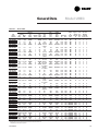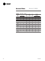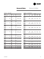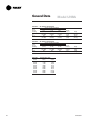
1
Electric Unit Heaters
Model UHAA
Model UHWA
Model UHRA
Model UHXA
Model UHEC
Model UHCA
August 2005
UH-PRC003-EN
Introduction
Introduction
Electric unit heaters have been a traditional means of heating hard-to-warm spaces for many years. Their uncomplicated
approach in auxiliary heating make them easy to install and maintain. Their versatile characteristics allow Trane’s
electric unit heaters to fill nearly every heating application gap, while their structural integrity makes them a reliable
heat source to blend into today’s building décor.
Trane’s electric unit heaters are available in 6 variations. The following chart presents a brief overview of the different
electric unit heater models Trane offers.
Model
UHEC 3 to 50 kW
Description
Application
Horizontal and Vertical Spot
Heating Electric Unit Heater
Applied as an auxiliary heat source
in walkways, stairways, vestibules,
and entrances. The horizontal and
vertical spot heater may be used in
commercial, industrial and
institutional applications.
Hose-Down, Corrosion-Resistant
Electric Unit Heater
Used in industrial applications where
dirt or dust may be extensive. The
totally enclosed, watertight casing is
corrosion-resistant for non-hazardous
locations.
UHXA 3 to 25 kW
Explosion-Proof Electric Unit Heater
Designed for hazardous locations, the
UHXA model may be applied where
flammable gases, vapors, powdered
metals or dust may be present.
UHCA 2 to 5 kW
Commercial, Ceiling-Mounted
Electric Unit Heater
The surface- or recessed mounted
model may be applied in restricted
areas or where wall space is limited.
This may included vestibules, lobbies,
rest rooms, small-offices or guard
buildings.
UHWA 2 to 5 kW
Heavy Duty, Wall Mounted
Electric Unit Heater
Suited for public buildings such as
schools, stores, offices, dormitories,
hospitals and transportation
terminals.
UHRA 3 to 48 kW
Series 20 and 50
UHAA 1.5 to 4.8 kW
© 2005 American Standard Inc. All rights reserved.
Architectural Wall Mounted
Electric Unit Heater
The rugged construction and
attractive design of the UHAA model
make them appropriate for offices,
lobbies, and reception areas for
schools and dormitories.
UH-PRC003-EN
Contents
UH-PRC003-EN
Introduction
2
Features and Benefits
4
Application Considerations
13
Selection Procedure
14
Model Number
15
General Data
19
Control Wiring
29
Dimensional Data
32
Options
39
Mechanical Specifications
42
3
Features and
Benefits
Electric Unit Heaters
• Thirty-seven models to choose from
ranging from 3.3 to 50 kW. Available for
208, 240/208, 277 or 480-volt operation.
• One unit can be used for either
horizontal or vertical discharge.
• Specially designed inlet louvers, venturi
and outlet diffuser provide uniform air
temperature and throw characteristics.
• Single-phase units, easily converted to
three-phase power, are available in 3.3
to 10 kW for 208 and 240-volt
operation.
• Two-speed fan operation standard on
25 kW units and above.
• Meets all requirements of UL listing
standard 1278 when installed as
directed.
UHEC electric unit heaters are ideal for
applications ranging from new
construction to auxiliary heat to
renovation. They are available in 37
models ranging from 3.3 kW to 50 kW. In
addition to a wide capacity range, each
compact, attractive unit can be mounted
in either a horizontal or vertical discharge
arrangement.
Flexibility
TheTrane electric unit heater shows its
flexibility in installation and operation.
Intended for industrial, commercial or
institutional use, theTrane electric unit
heater is available for 208 to 480-volt,
single or three-phase operation. Units
from 3.3 to 10 kW for 208 and 240-volt
operation may be converted easily from
single to three-phase operation in the
field.Two-speed fan operation on 25 kW
units and above provides greater airflow
flexibility.
Uniform Air Distribution
TheTrane unit heater uniformly directs
the air to exactly where it’s needed. A
specially designed deep-drawn venturi
assures uniform air distribution. The
outward-drawn venturi channels the air
forward for maximum, uniform air throw.
Outlet diffusers are provided to properly
direct the heated discharge air.
Model UHEC
Trane electric unit heaters are designed
with totally enclosed, permanently
lubricated industrial motors. The
air-over-motor design reduces operating
temperatures, promoting long motor life.
Thermal overloads provide additional
protection for major circuits, in case
normal operating temperatures are
exceeded.
Quick and Easy
Low-Cost Installation
Installation time and costs are minimized.
Compact and completely factory wired,
the Trane electric unit heater requires
only a single-source power supply
connection. The units are available with
factory installed 24-volt control
transformers and contactors.
In order to minimize the potential for hot
spots on the heating coil, inlet louvers
evenly distribute intake air over the entire
heating element.
Casing — Die-formed heavy-gauge steel
with baked enamel finish.
Intake Louvers — Designed to provide
uniform air distribution across entire
heating element.
Outlet Louvers — Individually adjustable
from 30° up to 45° down.
Element — High mass, all steel finned,
tubular heating element.
Motor and Fan — Totally enclosed,
permanently lubricated, sealed bearing,
all-angle motor and fan combination
through 20 kW and two-speed permanent
capacitor-type motor on 25 through 50
kW units.
Contactors — All units 25 kW and larger
are equipped with two contactors and
two element banks for either single or
two-stage heating operation.
Transformer — 24-volt control circuit for
closer temperature control and added
safety. Standard on most models,
optional on 3.0 and 5 kW 208, 240/208,
277-volt models.
Thermal Overloads — Automatic reset
thermal cutouts disconnect motor and
element in the event normal operating
temperatures are exceeded.
Fusing — Element, motor and transformer
primary fusing are factory installed and
wired where required to NEC. Branch
circuit fusing installed where required on
48 amps and up.
LISTED
4
Terminal Panel — Single-point terminal
board wiring for easy control accessories
installation.
Access Panel — Full width access panel
secured by quarter-turn fasteners.
UH-PRC003-EN
Features and
Benefits
Model UHEC
Mounting the unit is easily accomplished
with the use of hanger rods connected to
weld nuts on the unit casing. An
accessory mounting bracket is available
for single-point mounting. Field installed
accessories such as built-in thermostats,
disconnect switches and summer fan
switches are provided with spade
terminals for easy installation to a singlepoint terminal board.
Reliable Operation
Trane electric UHEC unit heaters operate
reliably when installed and operated as
directed. In addition to meeting all
requirements of UL listing standard 1025,
the heating element is backed with a fiveyear warranty.
Easy Access
In the event that service is required, easy
access to the control components is
provided with a full-length access panel
secured by quarter-turn fasteners. For
added convenience, unit wiring diagrams
are located inside the access panel for
easy reference during installation and
servicing.
Vertical Discharge
Horizontal Discharge
UH-PRC003-EN
5
Features and
Benefits
Model UHRA
Hose-Down Electric Unit Heaters
Trane UHRA hose-down electric unit
heaters are constructed for use in areas
that require washing or hosing of
equipment due to a dirty or dusty
industrial environment in
non- hazardous locations. The
totally enclosed, watertight casing made
with corrosion-resistant material, makes
the unit ideal for industrial heating
applications. All controls are built-in and
the safety temperature controls are
wired in a nonmetallic NEMA 4x control
panel with single-point power
connections.
Standard Features
• Heavy-duty 304 stainless steel casing
• NEMA 4x nonmetallic control panel
• 24-volt transformer and control circuit
• Three-position switch (off - heat - fan)
• Disconnect switch with enclosure
interlock
• Capillary thermostat with stainless steel
sensor
• Automatic reset thermal cutout
• Totally enclosed UL listed motor
• Pilot light (power on indicator)
• Chrome-plated finned tubular element
• Control panel on bottom of unit for ease
of installation and service
Control Enclosure
• Single-point power connection
• Meets all UL, NEC and OSHA
requirements (when installed as
directed)
• Corrosion-resistant in high humidity and
water-saturated areas (for areas where
corrosion-resistance is needed in
non-hazardous areas).
Easy-mount bracket for Use with
Field- Installed Hanger or Optional
Mounting Brackets
304 Stainless Steel Casing
Plated Inlet Grille
Totally Enclosed Motor
Stainless Steel
Discharge Grille
Aluminum Fan Blade
Element
Thermostat
Three-Position Fan Switch
Pilot Light (Heater
Energized)
6
Door Interlock
Disconnect Switch
(Optional)
NEMA 4x Non-Metallic Enclosure
Control Components (24-Volt Standard)
UH-PRC003-EN
Features and
Benefits
Model UHXA
Trane Explosion-Proof
Electric Unit Heaters
Pressure Relief Valve
Rated at 200 PSI
Epoxy Coated 14-Gauge Cold Rolled
Steel Cabinet
Spiral Aluminum FinnedTubular Steel
Heat Exchanger Core Liquid Filled
Operation (see page 3)
14-Gauge Steel Adjustable
Louvers
with Minimum
Position Stops
Cast Aluminum Control Enclosure
with Oversized Opening
Built-In Load Carrying Contactor
Protective Heating Element Cover
Copper Sheathed ImmersionType
Heating Element
UH-PRC003-EN
Etched Aluminum Data Plates
Riveted to Case
High Performance Aluminum Fan
Blades (not shown)
7
Features and
Benefits
Liquid to air heat exchanger with low
watt density heating elements in
ethylene glycol solution that provides
freeze protection to -45°C.
Model UHXA
Designed for rugged industrial
applications in hazardous locations
where the possibility of explosion or fire
exists due to the presence of certain
flammable gases, vapors, powdered
metals or dusts.
• Permanently sealed, liquid to air, finned
tube heat exchanger core.
• Ethylene glycol water mixture used as
heat transfer fluid in the heater core,
providing -45°C, (-49°F) freeze damage
protection.
• High-performance electric motor
driven fan blows air across finned tubes
to effect uniform heat transfer and area
heat distribution.
• Automatic reset capillary type high limit
provides high temperature regulation
and is rated for 100,000 cycles of
service.
• Stainless steel and aluminum pressure
relief valve handles any over-pressure.
• 14-gauge steel cabinet contains heater
core, motor and fan assembly.
• Narrow gap safety fan guard shields all
moving parts.
• Adjustable louvers allow directional
control of air.
• Copper conductor wires enclosed in
rigid metal conduits carry all electrical
power.
• Box lugs are furnished for field
connections within an approved
enclosure.
Ball bearing permanently lubricated
explosion-proof motor. Chrome plated
guard meets OSHA requirements.
Heavy-duty control contactor with
24-volt control circuit provided on all
models.
8
UH-PRC003-EN
Features and
Benefits
Heavy-Duty Wall Heaters
Trane heavy-duty wall mounted electric
forced-air unit heaters are
architecturally styled in a
vandal- resistant design for all
commercial, institutional and many
industrial applications. They are
particularly suited for schools, office
buildings, dormitories, stores, hospitals
and other public buildings.
The high capacity and wide range of
voltage/phase and control systems
provides application versatility to meet
most installation requirements. A wide
selection of built-in factory installed and
wired, pre-engineered control systems
minimizes system design and
installation time.
Model UHWA
Series 20 and 50
All units are equipped with zero voltage
reset thermal cut-outs for overheat
protection and a totally enclosed,
permanently lubricated motor. Optional
circuit breaker, control transformer and
a selection of integral or wall-mounted
thermostat controls are part of the unit
package.
Solid Construction and
Dependable Components
Sleeve
Sleeve for surface or semi-recessed
installation. 16 gauge (1.5 mm
thickness) zinc coated steel.
Louvered Grille
Heavy-duty welded steel for maximum
impact resistance. Closely spaced
(pencil proof), tamperproof.
Element
Totally enclosed, corrosion-resistant.
Maximum finning for lower operating
temperature and longer life. Will not
become dust clogged. (No filter
required.)
Motor Shield
Protects motor by separating return air
from heated air.
Thermal Cut-Out
Exclusive “zero voltage reset” type for
high degree of effectiveness if normal
operating temperatures are exceeded.
Transformer
Optional factory assembled and wired
in 50 Series. Choice of 24 or 120 volt
secondary.
Entrance Terminals
Line side termination enclosed for safe
servicing of heaters when supplied with
circuit breakers.
Circuit Breakers
Reduces installation cost by allowing
one or more heaters to be wired from
feeder and feeder tap. Separate control
circuit switch supplied when required.
All power can be turned off before front
cover is removed.
Series 50 with exposed thermostat knob Series 20 and 50 with tamper-resistant
and covered circuit breaker and control thermostat cover plate which is included
switch only
with each heater.
UH-PRC003-EN
Motor
Heavy-duty unit bearing, permanently
lubricated, totally enclosed, impedance
protected.
Blade
Highly efficient, space saving bladeover-motor design, individually
balanced.
Contactor
Optional, definite purpose, heavy-duty
type with flame path separators and
dust covers. Choice of heater voltage,
120 volt or 24 volt holding coil.
Thermostat
Optional heavy-duty hydraulic snap
action type with sensing bulb in return
airstream. Disconnects all ungrounded
conductors in OFF position.
Series 50 with tamper-resistant cover
removed.
9
Features and
Benefits
Model UHWA
Series 20 and 50
• Architecturally styled and
vandal- resistant for schools, churches,
stores, office buildings, transportation
terminals, dormitories, hospitals.
• Use in vestibules, entrance ways,
lobbies, corridors, stairways, reception
rooms, rest rooms, offices.
• Simple application design — Wide
selection of built-in, factory installed and
wired, pre-engineered control systems.
Saves design and on-the-job time.
• Versatile application — Higher capacity
and wider range of voltage/phase and
control systems than any similar
heaters previously available.
front withstands with less than
• Heater
1
/16” (1.6 mm) permanent distortion,
10.8 ft lbs (324 poundals) impact and
400 lbs (181.4 kg) static force applied to
an 8 sq. in. (5160 sq. mm) area at center
grille location.
10
UH-PRC003-EN
Features and
Benefits
Model UHCA
Series 70 and 80
Commercial and Industrial
Ceiling - Mounted Fan Forced Heaters
Series 70 and 80 Features
• Crisp, unique styling to blend into any
architectural design — unit designed for
long life and warranted for five years.
• Higher velocity ceiling-mounted heater
gets air down to warm those hard to
heat areas where public accessibility is
not desired or where wall area is
restricted.
• Single or multiple installations at a
fraction of the cost of cabinet unit
heaters.
• Five-year warranty.
• 2,000 to 5,000 watts.
• 208, 204 V single and three-phase.
277 V single-phase.
• UL listed and conform to Underwriters’
Standard 1025.
Commercial and Institutional
Applications
• Use in vestibules, entrance ways,
lobbies, restrooms and small office and
guard building applications.
• A unique design offers surface and
recessed applications with higher
wattage capacity and wider range of
voltage and phase capabilities than
other heaters of this type.
• Control: Line voltage and low voltage
control capabilities using accessory
thermostat (see page 8).
• Unit mounted controls for Series 80
only with fan purge.
Series 80
Recess mounted for 2’ (609.6 mm) x
2’ (609.6 mm) “T” bar or plaster
ceilings
Mounting Bracket — features swing up
installation on surface mounted 70
Series. Bracket center notched to
accept screws of ceiling outlet box
(installed by others). Recessed heater
80 Series has junction box attached to
heater can.
Motor — heavy-duty unit bearing,
permanently lubricated, totally
enclosed, impedance protected.
Blade — highly efficient, space-saving
blade over motor design, individually
balanced.
Thermal Cut-Out — exclusive “zero
voltage reset” type for highest degree
of effectiveness in event normal
operating temperatures are exceeded.
Heater must be manually shut off for
five minutes to reset. (See page 8.)
Element — totally enclosed and
corrosion resistant. Maximum finning
for lower operating temperatures and
long life. Will not become dust clogged.
(No filter required.)
Discharge Venturi — bull’s-eye design
permitting heated air to leave in
uniform pattern.
Plaster Trim — optional plaster trim for
recessed mounted heaters (series 80)
only. Provides finished ceiling
appearance.
UH-PRC003-EN
11
Features and
Benefits
Model UHAA
Series 3320
Architectural Quality
• Built - in tamper resistant thermostat
• Built - in tamper resistant disconnect
switch
• Richly styled, rugged grille
• Whisper-quiet sound level
• Fan delay
• Decorator designed for functional
beauty and versatility.
• Five-year element, limited warranty
• UL listed
Optional Accessories
3320EX33
Surface Mounting Adapter
Factory-Installed Accessories
Suffix R
Day/Night Relay
Rugged Grille — Grille made of 18
gauge (1.2 mm thickness) steel painted
with a dark brown baked enamel finish.
Richly Styled Grille — Grille is
highlighted by a snap-on, 14-gauge
(1.9 mm thickness) aluminum frame,
secured to the heater with an
inconspicuous fastener.
Element — Steel sheath with plate heat
exchanger.
Fan Delay Switch — To allow the fan to
continue to run for a short period after
the thermostat is satisfied, to expel
warm air from inside the heater. Also
delays fan on start up to insure delivery
of heated air.This switch also prolongs
element life.
“Unique” Vane Axial Fan Wheel —
Draws in large volumes of air then
quietly and gently discharges 175 cfm
(82.6 l/s) of heated air downward into
the room.
12
UH-PRC003-EN
Application
Considerations
Abbreviated descriptions of UL classes,
groups and divisions. Before selecting any
heater for a particular application, refer to
Article 500 as well as other standards
referenced in the National Electric Code.
• Class I: Equipment does not have
surface operating temperature in
excess of the ignition temperature of
the specific gas or vapor.
• Class II: Equipment does not have
surface temperature greater than the
ignition temperature of the specified
dust.
• Group D: Atmospheres such as but not
limited to acetone, alcohol, gasoline,
lacquer solvent vapors, natural gas,
propane or other gases or vapors of
equivalent hazard.
• Group E: Atmospheres containing
combustible metal dust regardless of
resistivity, or other combustible dust
of similar hazard characteristics
having resistivity of less than
105 ohm-centimeter.
• Group F: Atmospheres containing
carbon black, charcoal, coal or coke
dust.
• Group G: Atmospheres containing
combustible dust having resistivity of
105 ohm-centimeter or greater.
• Division I: A location in which ignitable
concentrations of flammable material
exist under normal operating conditions.
• Division II: Locations in which flammable
materials will normally be confined
within closed containers and escape
only in the case of accidental rupture,
breakdown or during maintenance
operations. Any equipment approved
for Division I is automatically also
approved for Division II.
Model UHXA
2
TheTrane explosion-proof electric unit
heaters have been listed by the
Underwriters Laboratories for maximum
surface temperatures. Use only in
atmospheres having an ignition
temperature higher than 165°C (T3B) for
Class I and Class II operation.
3
Altitude restrictions — see specification
table.
4
Heater must be installed in permanently
mounted upright position and connected
to fixed power supply.
5
Do not operate in atmospheres corrosive
to steel and aluminum.
Selection and application of electric unit
heaters should consider the location,
classification and properties of flammable
vapors, liquids, gases, dusts and fibers
which may be present. Each room,
section or area should be considered
individually.
For further information consult National
Electric Code and National Fire Prevention
Association (ANSI) standards. All models
conform to OSHA requirements when
mounted at any height.
Installation Conditions
1
Refer to owner’s manual.
UH-PRC003-EN
13
Selection
Procedure
Model UHEC, UHRA, UHXA, UHWA,
UHCA, UHAA
Calculate the heating loads using the
NEMA, ASHRAE, or other accepted
heating load calculation method.
Determine the quantity and size of unit
heaters to be used.To maintain uniform
temperature and recommended air
circulation, it is suggested that cfm should
be adequate to accomplish three air
changes per hour.
For maximum comfort, the use of smaller
units with lower airflows is suggested to
provide more uniform temperature and
even airflow. In warehouses and storage
areas where uniform heat distribution
and temperature control is of lesser
importance, it is desirable to use fewer
units with greater capacity.
Model UHEC and Model UHRA
Unit heaters in the vertical position are
ideal for use in high ceiling areas and
areas where low mounting heights
would interfere with personnel or
equipment activity. Units mounted in the
vertical discharge position should not be
mounted higher than the unit’s published
maximum mounting height ratings.
When unit heaters are used to temper
areas such as loading dock doors, one or
more units should be arranged to
blanket the exposed opening.
Unit heaters mounted in the horizontal
discharge position are most effective
when heat is directed along the perimeter
of the building wall with the airflow of
each unit supporting the airflow of the
other units to create a constant flow of
warm air.
14
UH-PRC003-EN
Model Number
Description
Model UHEC,
UHRA, UHXA
Model UHEC
Model UHRA
Model UHXA
Digits 1-3 — Electric Unit Heater
Digits 1-3 — Electric Hose-Down Corrosion
Resistant Unit Heater
Digits 1-3 —
Electric Explosion-Proof
Unit Heater
Digit 4 — Development Sequence
Digit 4 — Development Sequence
Digits 5-6 — Unit Capacity
03 — 3.3 kW
05 — 5 kW
07 — 7.5 kW
10 — 10 kW
15 — 15 kW
20 — 20 kW
25 — 25 kW
30 — 30 kW
40 — 40 kW
50 — 50 kW
Digit 7 — Element Phase
1 — Single-phase
2
Single-phase/three-phase
(field convertible)
3 — Three-phase
Digit 8 — Element and Motor Voltage
A — 208 V
B — 240/208 V
C — 277 V — Single-phase only
D — 480 V — Three-phase only
Digit 9 — 24-Volt Control Transformer
0 — None - wired for direct line voltage
A — Transformer - for 24-volt control
circuits
Digit 4 — Development Sequence
Digits 5-6 — Unit Capacity
03 — 3.3 kW
05 — 5 kW
07 — 7.5 kW
10 — 10 kW
15 — 15 kW
20 — 20 kW
25 — 25 kW
30 — 30 kW
40 — 40 kW
48 — 48 kW
Digit 7 — Element Phase
1 — Single-phase
3 — Three-phase
Digit 8 — Element Voltage
A — 208 V
G — 240 V
C — 277 V
D — 480 V
F — 600 V
Digit 9 — 24-Volt Control
Transformer/Relay
A — Transformer/Relay — Standard
Digits 5-6 — Unit Capacity
03 — 3 kW
05 — 5 kW
07 — 7.5 kW
10 — 10 kW
15 — 15 kW
20 — 20 kW
25 — 25 kW
Digit 7 — Element Phase
1 — Single Phase
3 — Three Phase
Digit 8 — Voltage
A — 208 Volts
B — 240 Volts
D — 480 Volts
F — 600 Volts
Digit 9 — Control Voltage
1 — 24 Volts (STD)
2 — 120 Volts (For 208, 240 & 480 Volts only)
3 — 208 Volts (For 208 Volts only)
4 — 240 Volts (For 240 Volts only)
Digit 10 — Design Sequence
Digit 10 — Design Sequence
Digit 10 — Design Sequence
Digit 11 — Contactors
0 — None - wired for direct line voltage
A — Contactor - for 24-volt control circuits
UH-PRC003-EN
Digit 11 —Thermostat/off/on/fan switch
— Factory installed and wired
T — Thermostat/off/on/fan switch —
Standard
Notes:
1. Available in 3 phase only.
2. Available in 480 volts or 600 volts,
3 phase only.
3. Available for 3 kW, 5 kW and 7.5 kW in
208 and 240 volts and 10 kW in 240 volts
only.
15
Model Number
Description
Model UHWA
Digits 1-3: Unit Type
UHW = Electric Wall Mounted Unit Heater
Digit 4: Development Sequence
Digits 5 - 6: Unit Capacity
02 = 2 kW
03 = 3 kW
04 = 4 kW
05 = 5 kW
Digit 7: Element Phase
1 = 1 Phase/60 Cycle
3 = 3 Phase/60 Cycle
Digit 8: Element and Motor Voltage
A = 208 Volt
B = 240 Volt
C = 277 Volt
Digit 9: Unit Series
2 = Unit Series 20
5 = Unit Series 50
Digit 10: Current Design Sequence
Digit 11: Built-in Thermostat
0 = None
T = Unit Mounted Tamper Proof
Thermostat
Digit 12: Wall Box
2 = Series 20 Wall Box
5 = Series 50 Wall Box
Model UHWA
A = 4” (102 mm) Ext Surface Mounted
(20 Series)
B = 2” (51 mm) Ext Semi-Recessed
(20 Series)
C = 1” (25 mm) Ext Semi-Recessed
(20 Series)
D = 4” (102mm) Ext Surface Mounted
(50 Series)
E = 2” (51 mm) Ext Semi-Recessed
(50 Series)
F = 1” (25 mm) Ext Semi-Recessed
(50 Series)
Digit 14: Wall Mounted LineVoltage Thermostat
1 = DPST 1-Phase Line Voltage
2 = DPST 1-Phase Tamper Resistant
3 = DPST 3-Phase Line Voltage
4 = SPST Pilot Duty Line Voltage
5 = SPST Pilot Duty Tamper Resistant
Digit 15: Contactors
H = Line Voltage
J = 24V
K = 120V
Digit 18: Circuit Breaker
L = Unit Mounted
Digit 19: Transformer 24 Volt
M = 24V Transformer
Digit 20: Transformer 120 Volt
P = 120V Transformer
Digit 13: Extension Sleeves
0 = No Extension Sleeves
16
UH-PRC003-EN
Model Number
Description
Model UHCA
Digit 1-3: Unit Type
UHC = Electric Ceiling Mounted Commercial
Heater
Digit 4: Development Sequence
Digits 5-6: Unit Capacity
02 = 2 kW
03 = 3 kW
04 = 4 kW
05 = 5 kW
Digit 7: Element Phase
1 = 1 Phase/60 Cycle
3 = 3 Phase/60 Cycle
Digit 8: Element and Motor Voltage
A = 208 Volt
B = 240 Volt
C = 277 Volt
Digit 9: Unit Series
2 = Surface Mounted, Unit Series 70
5 = Recess Mounted, Unit Series 80
Digit 10: Current Design Sequence
Digit 12-13: Unit Mounted Thermostat
T1 = Single Pole Thermostat
T2 = Double Pole Thermostat
Model UHCA
Digit 19: Control Panels
A = 24V Control Panel for 208V, 1-Contactor
B = 24V Control Panel for 240V, 1-Contactor
C = 24V Control Panel for 277V, 1-Contactor
D = 24V Control Panel for 208V, 2-Contactor
E = 24V Control Panel for 240V, 2-Contactor
F = 24V Control Panel for 277V, 2-Contactor
G = 24V Control Panel for 208V, 3-Contactor
H = 24V Control Panel for 240V, 3-Contactor
J = 24V Control Panel for 277V, 3-Contactor
1 = 120V Control Panel for 208V, 1-Contactor
2 = 120V Control Panel for 240V, 1-Contactor
3 = 120V Control Panel for 277V, 1-Contactor
4 = 120V Control Panel for 208V, 2-Contactor
5 = 120V Control Panel for 240V, 2-Contactor
6 = 120V Control Panel for 277V, 2-Contactor
7 = 120V Control Panel for 208V, 3-Contactor
8 = 120V Control Panel for 240V, 3-Contactor
9 = 120V Control Panel for 277V, 3-Contactor
Digit 20: Low Voltage Thermostat Option
0 = No Low Voltage T-Stat
7 = Low Voltage T-Stat
Digit 21: Thermal Relay with Transformer
0 = No Thermal Relay
A = SPST Relay w/Transformer
Digit 22: Tamper Proof Kit
8 = Tamper Proof Kit
Digit 14: Unit Mounted Disconnect
S = Unit Mounted Disconnect Switch
Digit 15-16: Unit Mounted Relay
R1 = Unite Mounted 24 Volt Transformer/Relay
R = Unit Mounted Line Voltage Relay
R2 = Unit Mounted 120 Volt Relay
Digit 17: Plaster Trim
A = Plaster Trim
Digit 18: Wall Mounted Line Voltage Thermostat
1 = DPST 1-Phase Line Voltage Thermostat
2 = DPST 1-Phase Tamper Resistant Thermostat
3 = DPST 3-Phase Line Voltage Thermostat
4 = SPST Pilot Duty Line Voltage Thermostat
5 = SPST Pilot Duty Tamper Resistant
Thermostat
UH-PRC003-EN
17
Model Number
Description
Model UHAA
Model UHAA
Digit 9: Built-in Thermostat
T = Unit Mounted Tamperproof Thermostat
Digit 1 - 3: Unit Type
UHA = Electric Architectural Wall Heater
Digit 10: Current Design Sequence
Digit 4: Development Sequence
Digit 11: Unit Mounted Disconnect
D = Unit Mounted Disconnect Switch
Digits 5–6: Unit Capacity
15 = 1.5 kW
02 = 2 kW
03 = 3 kW
04 = 4 kW
48 = 4.8 kW
Digit 7: Element Phase
1 = 1 Phase/60 Cycle
Digit 12: Day/Night Relay
0 = None
R = Unit Mounted Day/Night Relay
Digit 13: Surface Mounting Adapter Option
0 = None
A = 3320EX33 Surface Mounting Adapter
Digit 8: Element and Motor Voltage
A = 208 Volt
B = 240 Volt
C = 277 Volt
E = 120 Volt
18
UH-PRC003-EN
General Data
Model UHEC
Table GD-1 — Model UHEC
Electrical Data
Unit
Model
Number
UHEC-031A0C0
UHEC-031B0C0
UHEC-031AACA
UHEC-032A0C0
UHEC-032B0C0
Capacity
kW
Btu/Hr
Rating
(000)
3.3
11.2
3.3/2.5 11.2/8.5
3.3
11.2
3.3
11.2
3.3/2.5 11.2/8.5
Element
and
Motor
Voltage
208
240/208
208
208
240/208
UHEC-031C0C0
UHEC-031CACA
UHEC-033DACA
UHEC-031BACA
UHEC-032AACA
UHEC-032BACA
3.3
3.3
3.3
3.3/2.5
3.3
3.3/2.5
11.2
11.2
11.2
11.2/8.5
11.2
11.2/8.5
277
277
480
240/208
208
240/208
1
1
3
1
1-3
1-3
UHEC-051A0C0
UHEC-052AACA
UHEC-051B0C0
UHEC-052A0C0
UHEC-052B0C0
5.0
17.1
5.0
17.1
5.0/3.7 17.1/12.8
5.0
17.1
5.0/3.7 17.1/12.8
208
208
240/208
208
240/208
1
1-3
1
1-3
1-3
UHEC-052BACA
5.0/3.7 17.1/12.8
240/208
1-3
UHEC-051C0C0
UHEC-053DACA
UHEC-051AACA
UHEC-051BACA
UHEC-05ACACA
UHEC-072AACA
5.0
17.1
5.0
17.1
5.0
17.1
5.0/3.7 17.1/12.8
5.0
17.1
7.5
25.6
277
480
208
240/208
277
208
1
3
1
1
1
1-3
UHEC-072BACA
7.5/5.6 25.6/19.2
240/208
1-3
UHEC-071CACA
7.5
25.6
UHEC-073DACA
7.5
25.6
UHEC-102AACA
10.0
34.1
UHEC-102BACA 10.0/7.5 34.1/25.6
277
480
208
240/208
1
3
1-3
1-3
UHEC-101CACA
UHEC-103DACA
UHEC-153AACA
UHEC-153BACA
UHEC-153DACA
UHEC-203BACA
UHEC-203DACA
UHEC-253AACA
UHEC-253BACA
UHEC-253DACA
UHEC-303AACA
UHEC-303BACA
UHEC-303DACA
UHEC-403AACA
UHEC-403BACA
UHEC-403DACA
UHEC-503AACA
UHEC-503BACA
UHEC-503DACA
277
480
208
240/208
480
240/208
480
208
240/208
480
208
240/208
480
208
240/208
480
208
240/208
480
1
3
3
3
3
3
3
3
3
3
3
3
3
3
3
3
3
3
3
10.0
34.1
10.0
34.1
15.0
51.2
15.0/11.2 51.2/38.4
15.0
51.2
19.7/14.8 67.2/50.5
20.0
68.3
25.0
85.3
25.0/18.7 85.3/64.0
25.0
85.3
30.0
102.4
30.0/22.5 102.4/76.8
30.0
102.4
40.0
136.5
40.0/30.0136.5/102.4
39.0
133.1
50.0
170.6
50.0/37.5170.6/128.0
50.0
170.6
Element
Phase
1
1
1
1-3
1-3
Std.
Max.
Control
Amp
Voltage Rating
208
15.9
240/208 13.7/11.9
24
15.9
208 15.9/9.2†
240/208 13.7/11.9
7.9/6.9†
277
11.9
24
11.9
24
4.0
24
13.7/11.9
24
15.9/9.2†
24
13.7/11.9
7.9/6.9†
208
24
240/208
208
240/208
Air Delivery Data
Airflow Approx. Horiz. Rec. Max.
At
Air Rise Air
Mounting
Outlet @ Outlet Throw Height (Ft)
(Cfm)
(F)
(Ft) Horiz. Vert.
400
26
12
9
9
400
26
12
9
9
400
26
12
9
9
400
26
12
9
9
400
26
12
9
9
Min.
Circuit
Fuse
Size
20A
20A/15A
20A
20A
20A/15A
Supply
Wire
Gauge
(60°C)
12G
12GA/14GA
12G
12GA
12GA/14GA
Motor Data
Hp
Rpm
1/125 1550
1/125 1550
1/125 1550
1/125 1550
1/125 1550
15A
15A
15A
20A/15A
20A
20A/15A
14GA
14G
14GA
12GA/14GA
12GA
12GA/14GA
1/125
1/125
1/125
1/125
1/125
1/125
1550
1550
1550
1550
1550
1550
400
400
400
400
400
400
26
26
26
26
26
26
12
12
12
12
12
12
9
9
9
9
9
9
9
9
9
9
9
9
8GA
8GA
10GA/10GA
8GA
10GA/10GA
1/125
1/125
1/125
1/125
1/125
1550
1550
1550
1550
1550
400
400
400
400
400
40
40
40
40
40
12
12
12
12
12
9
9
9
9
9
9
9
9
9
9
10GA/10GA 1/125
1550
400
40
12
9
9
10GA
14GA
8GA
10GA/10GA
10GA
6GA
1/125
1/125
1/125
1/125
1/125
1/50
1550
1550
1550
1550
1550
1550
400
400
400
400
400
700
40
40
40
40
40
34
12
12
12
12
12
22
9
9
9
9
9
10
9
9
9
9
9
12
8GA/8GA
1/50
1550
700
34
22
10
12
8GA
14GA
4GA
4GA/6GA
1/50
1/50
1/50
1/50
1550
1550
1550
1550
700
700
700
700
34
34
45
45
22
22
22
22
10
10
10
10
12
12
14
14
6GA
12GA
4GA
6GA/6GA
10GA
4GA/4GA
8GA
2GA
3GA/4GA
8GA
1GA
1GA/3GA
6GA
1/0*
1/0/1GA
4GA
2/0*
2/0/2/0
3GA
1/50
1/50
1/20
1/20
1/20
1/20
1/20
1/12
1/12
1/15
1/12
1/12
1/15
1/4
1/4
1/5
1/4
1/4
1/5
1550
1550
1550
1550
1550
1550
1550
1550
1550
1550
1550
1550
1550
1550
1550
1550
1550
1550
1550
700
700
1100
1100
1100
1100
1100
2000/1800
2000/1800
2000/1800
2000/1800
2000/1800
2000/1800
3100/2800
3100/2800
3100/2800
3100/2800
3100/2800
3100/2800
45
45
43
43
43
57
57
40/44
40/44
40/44
47/53
47/53
47/53
40/45
40/45
40/45
51/56
51/56
51/56
22
22
32
32
32
32
32
45
45
45
40
40
40
55
55
55
50
50
50
10
10
11
11
11
12
12
12
12
12
12
12
12
15
15
15
15
15
15
14
14
20
20
20
18
18
22
22
22
20
20
20
24
24
24
22
22
22
24.1
35A
24.1/13.9
35A
20.9/18.1
30A/25A
24.1/13.9†
35A
20.9/18.1
30A/25A
12.1/10.4†
24
20.9/18.1
30A/25A
12.1/10.4†
277
18.1
25A
24
6.1
15A
24
24.1
35A
24
20.9/18.1
30A/25A
24
18.1
25A
24
36.1 20.8
50A
20.8†
24
31.3/27.1
40A/35A
18.1/15.6†
24
27.1
35A
24
9.1
15A
24 47.8/27.7†
60A
24
42.2/36.1
60A/50A
24/20.8†
24
36.1
50A
24
12.1
20A
24
41.7
60A
24
36.1/31.3
50A/40A
24
18.1
25A
24
47.8/41.1
70A/60A
24
24.1
35A
24
69.5
90A
24
60.2/52.1
80A/70A
24
30.1
40A
24
83.4
110A
24
72.3/62.5 100A/80A
24
36.2
50A
24
111.2
150A
24
96.4/83.4 125A/110A
24
47.0
70A
24
139.0
175A
24 120.5/104.3 175A/175A
24
60.3
80A
Notes: 1. Maximum amp rating indicates single-phase on those units suitable for both single and three-phase. 2. 25 through 50 kW models are wired for two-stage, low voltage control. These units
are also equipped with two-speed motors for Hi-Lo fan operation with addition of fan switch option. 3. Dual voltage unit ratings indicate highest voltage performance. 4. 1 kW equals 3,413 BTU.
*Supply wire on these models should have insulation rated 75°C minimum.
† Amp Rating for three-phase operation.
UH-PRC003-EN
19
General Data
Model UHEC
Table GD-2 — Model UHEC — Metric
Unit Heater
Capacity
kW
Rating
3.3
5.0
7.5
10
15
20
25
Motor Data
Watts
R.P.S.
6
25.8
6
25.8
14
25.8
14
25.8
37
25.8
37
25.8
62
25.8
25
480/3 Mtr
30
50
25.8
62
25.8
30
480/3 Mtr
40
50
25.8
186
25.8
40
480/3 Mtr
50
149
25.8
186
25.8
50
480/3 Mtr
149
25.8
Airflow
at
Outlet
(L/S)
189
189
330
330
519
519
944/
849
944/
849
944/
849
944/
849
1463/
1321
1463/
1321
1463/
1321
1463/
1321
Approx.
Air Rise
@ Outlet
(C)
14.4
22.2
18.9
25.0
23.9
31.7
22.2/
24.4
22.2/
24.4
26.1/
29.4
26.1/
29.4
22.2/
25.0
22.2/
25.0
28.3/
31.1
28.3/
31.1
Horiz.
Air
Throw
(M)
3.7
3.7
6.7
6.7
9.8
9.8
13.7
13.7
13.7
13.7
12.2
12.2
12.2
12.2
16.8
16.8
16.8
16.8
15.2
15.2
15.2
15.2
Rec. Max
Mounting
Height (M)
Horizontal
Vertical
2.7
2.7
2.7
2.7
3.0
3.7
3.0
4.3
3.4
6.1
3.7
5.5
3.7
6.7
3.7
6.7
3.7
6.7
3.7
6.7
3.7
6.1
3.7
6.1
3.7
6.1
3.7
6.1
4.6
7.3
4.6
7.3
4.6
7.3
4.6
7.3
4.6
6.7
4.6
6.7
4.6
6.7
4.6
6.7
Note 1. 25 through 50 kW models are equipped with two-speed motors for Hi-Lo fan operation with addition of fan switch
option.
20
UH-PRC003-EN
General Data
Table GD-4 — Air Delivery Data
Table GD-3 — Model UHRA
Unit
Model
Number
kW
UHRA Rating
031AAAT
033AAAT
031GAAT
033GAAT 3.3
031CAAT
033DAAT
033FAAT
051AAAT
053AAAT
051GAAT
053GAAT 5.0
051CAAT
053DAAT
053FAAT
071AAAT
073AAAT
071GAAT
073GAAT 7.5
071CAAT
073DAAT
073FAAT
101AAAT
103AAAT
101GAAT
103GAAT
10
101CAAT
103DAAT
103FAAT
151AAAT
153AAAT
151GAAT
153GAAT
15
153DAAT
153FAAT
203AAAT
203GAAT
20
203DAAT
203FAAT
253AAAT
253GAAT
25
253DAAT
253FAAT
303AAAT
303GAAT
30
303DAAT
303FAAT
403DAAT
40
403FAAT
483DAAT
48
483FAAT
UH-PRC003-EN
Btu/Hr
11,200
17,100
25,600
34,130
51,200
68,260
85,325
102,390
136,520
163,824
Motor &
Heater
Volts/
Control
Phase
Volts
208/1
208/3
240/1
240/3
24
277/1
480/3
600/3
208/1
208/3
240/1
240/3
24
277/1
480/3
600/3
208/1
208/3
240/1
240/3
24
277/1
480/3
600/3
208/1
208/3
240/1
240/3
24
277/1
480/3
600/3
208/1
208/3
240/1
240/3
24
480/3
600/3
208/3
240/3
24
480/3
600/3
208/3
240/3
24
480/3
600/3
208/3
240/3
24
480/3
600/3
480/3
24
600/3
480/3
24
600/3
Model UHRA
Max
Amp
Rating
15.9
9.2
13.8
8.0
12.0
4.0
3.2
24.1
13.9
20.9
12.1
18.1
6.1
4.9
36.1
20.9
31.3
18.1
27.1
9.1
7.3
48.1
27.8
41.7
24.1
36.2
12.1
9.7
72.2
41.7
62.5
36.2
18.1
14.5
55.6
48.2
24.1
19.3
69.5
60.3
30.2
24.1
83.4
72.3
36.2
29.0
48.2
38.6
57.9
46.3
Motor
HP
Motor
RPM
35 mhp
(21 w)
1550
(26 rps)
35 mhp
(21 w)
1550
(26 rps)
35 mhp
(21 w)
1550
(26 rps)
35 mhp
(21 w)
1550
(26 rps)
35 mhp
(21 w)
1550
(26 rps)
1/3
(249 w)
1625
(27 rps)
1/3
(249 w)
1625
(27 rps)
1/3
(249 w)
1625
(27 rps)
1/3
(249 w)
1/3
(249 w)
1625
(27 rps)
1625
(27 rps)
Unit
Model
Number
UHRA
031AAAT
033AAAT
031GAAT
033GAAT
031CAAT
033DAAT
033FAAT
051AAAT
053AAAT
051GAAT
053GAAT
051CAAT
053DAAT
053FAAT
071AAAT
073AAAT
071GAAT
073GAAT
071CAAT
073DAAT
073FAAT
101AAAT
103AAAT
101GAAT
103GAAT
101CAAT
103DAAT
103FAAT
151AAAT
153AAAT
151GAAT
153GAAT
153DAAT
153FAAT
203AAAT
203GAAT
203DAAT
203FAAT
253AAAT
253GAAT
253DAAT
253FAAT
303AAAT
303GAAT
303DAAT
303FAAT
403DAAT
403FAAT
483DAAT
483FAAT
kW
Cfm
Outlet
FPM
Outlet
F Deg.
Temp.
Rise
Outlet
Air
Throw
Feet
Rec.
Mtg.
Height
3.3
400
500
(189 L/S) (2540 MM/S)
26°F
(-3.3°C)
20 Ft.
(6.1 M)
6 Ft.
(1.8 M)
5.0
400
500
(189 L/S) (2540 MM/S)
40°F
(4.4°C)
20 Ft.
(6.1 M)
6 Ft.
(1.8 M)
7.5
400
500
(189 L/S) (2540 MM/S)
60°F
(16°C)
20 Ft.
(6.1 M)
6 Ft.
(1.8 M)
10
700
660
(330 L/S) (3353 MM/S)
45°F
(7.2°C)
28 Ft.
(8.5 M)
6 Ft.
(1.8 M)
15
700
660
(330 L/S) (3353 MM/S)
68°F
(20°C)
28 Ft.
(8.5 M)
6 Ft.
(1.8 M)
20
1400
1000
(661 L/S) (5080 MM/S)
45°F
(7.2°C)
35 Ft.
(10.7 M)
6 Ft.
(1.8 M)
25
1400
1000
(661 L/S) (5080 MM/S)
56°F
(13.3°C)
35 Ft.
(10.7 M)
6 Ft.
(1.8 M)
30
1400
1000
(661 L/S) (5080 MM/S)
68°F
(20°C)
35 Ft.
(10.7 M)
6 Ft.
(1.8 M)
40
1800
1000
(849 L/S) (5080 MM/S)
1800
1000
(849 L/S) (5080 MM/S)
70°F
(21°C)
84°F
(29°C)
42 Ft.
(12.8 M)
42 Ft.
(12.8 M)
6 Ft.
(1.8 M)
6 Ft.
(1.8 M)
48
21
General Data
Model UHRA
Table GD-5 — Air Delivery Characteristics
Heater
Capacity
(kW Rating)
3.3, 5.0
7.5
10, 15
Velocity of Air Movement (FPM)
Distance from Heater
6 Ft.
12 Ft.
24 Ft.
(1.8 M)
(3.7 M)
(7.3 M)
210
80
25
(12.8 M/S)
(4.9 M/S)
(1.5 M/S)
270
95
45
(16.5 M/S)
(5.8 M/S)
(2.7 M/S)
Throw
Distance
36 Ft.
(11 M)
46 Ft.
(14 M)
Weight
45 lbs.
(20.4 Kg)
55 lbs.
(24.9 Kg)
Throw
Distance
55 Ft.
(16.8 M)
65 Ft.
(19.8 M)
Weight
85 lbs.
(39 Kg)
130 lbs.
(59 Kg)
Table GD-6 — Air Delivery Characteristics
Heater
Capacity
(kW Rating)
20, 25,
30
40, 48
Velocity of Air Movement (FPM)
Distance from Heater
10 Ft.
20 Ft.
30 Ft.
(3.0 M)
(6.1 M)
(9.1 M)
750
450
300
(45.7 M/S)
(27.4 M/S)
(18.3 M/S)
900
500
350
(54.9 M/S)
(30.5 M/S)
(21.3 M/S)
Table GD-7 — Unit Electrical Data
Model
Number
UHRA-03
UHRA-05
UHRA-07
UHRA-10
UHRA-15
UHRA-20
UHRA-25
UHRA-30
UHRA-40
UHRA-48
22
Watts
3.300
5,000
7,500
10,000
15,000
20,000
25,000
30,000
40,000
48,000
BTU/Hr.
Output
11,261
17,062
25,594
34,125
51,188
68,250
85,313
102,375
136,500
163,800
UH-PRC003-EN
General Data
Model UHXA
Table GD-8 — Model UHXA
Unit Size
3 kW
5 kW
7.5 kW
10 kW
15 kW
20 kW
25 kW
Model No.
UHXA
031A1B
033A1B
033B1B
033B1B
033D1B
033F1B
051A1B
053A1B
051B1B
053B1B
053D1B
053F1B
071A1B
073A1B
071B1B
073B1B
073D1B
073F1B
103A1B
101B1B
103B1B
103D1B
103F1B
153A1B
153B1B
153D1B
153F1B
203D1B
203F1B
253D1B
253F1B
Volts/
Phase
208/1
208/3
240/1
240/3
480/3
600/3
208/1
208/3
240/1
240/3
480/3
600/3
208/1
208/3
240/1
240/3
480/3
600/3
208/3
240/1
240/3
480/3
600/3
208/3
240/3
480/3
600/3
480/3
600/3
480/3
600/3
Motor
HP
1
/4
(186W)
1
/4
(186 W)
1
/4
(186 W)
1
/4
(186 W)
1
/2
(186 W)
1
/2
(373 W)
1
/2
(373 W)
Heater
Amps
14.4
8.3
12.5
7.2
3.6
2.9
24.0
13.9
20.8
12.0
6.0
4.8
36.1
20.8
31.3
18.0
9.0
7.2
27.8
41.7
24.1
12.0
9.6
41.6
36.1
18.0
14.4
24.1
19.2
30.1
24.1
Line
Amps
16.3
9.8
14.8
8.6
4.3
3.5
26.0
15.4
23.1
13.4
6.7
5.4
38.0
22.3
33.6
19.4
9.7
7.8
29.3
44.0
25.5
12.7
10.2
43.5
38.1
19.0
15.2
25.1
20.0
31.1
24.9
BTU/
Hr.
Air Temp.
Rise
Deg. F
Air Temp.
Rise
Deg. C
10239
16.6
9.2
17065
27.6
15.3
25598
41.4
23.0
34130
21.7
12.1
51195
19.2
10.7
68260
26.2
14.6
85325
32.8
18.2
Min. Cir.
Ampacity
20.4
12.3
18.5
10.8
5.4
4.4
32.4
19.2
28.9
16.8
8.4
6.8
47.5
27.9
42.0
24.3
12.2
9.8
36.6
55.0
31.8
15.9
12.8
54.4
47.6
23.8
19.0
31.3
25.1
38.8
31.1
Max
Fuse
Amps
25
15
20
15
15
15
35
20
30
20
15
15
50
30
45
25
15
15
40
60
35
20
15
60
50
25
20
35
30
40
35
Min*
Wire
AWG
10
14
12
14
14
14
8
12
10
12
14
14
8
10
8
10
14
14
8
6
8
12
14
6
8
10
12
8
10
8
8
*Supply conductors must be suitable for 90°C
1. 1 watt equals 3.413 Btu.
2. 1 kW equals 3,413 Btu.
3. 24 volt control voltage is standard and includes built-in contactor and 24 volt control transfer.
UH-PRC003-EN
23
General Data
Model UHXA
Table GD-9 — Model UHXA with 120 Volt Control Voltage
Unit Size
3 kW
5 kW
7.5 kW
10 kW
15 kW
20 kW
25 kW
Model No.
UHXA
031A2B
033A2B
033B2B
033B2B
033D2B
051A2B
053A2B
051B2B
053B2B
053D2B
071A2B
073A2B
071B2B
073B2B
073D2B
103A2B
101B2B
103B2B
103D2B
153A2B
153B2B
153D2B
203D2B
253D2B
Volts/
Phase
208/1
208/3
240/1
240/3
480/3
208/1
208/3
240/1
240/3
480/3
208/1
208/3
240/1
240/3
480/3
208/3
240/1
240/3
480/3
208/3
240/3
480/3
480/3
480/3
Motor
HP
1
/4
(186W)
1
/4
(186 W)
1
/4
(186 W)
1
/4
(186 W)
1
/2
(186 W)
1
/2 (373 W)
1
/2 (373 W)
Heater
Amps
14.4
8.3
12.5
7.2
3.6
24.0
13.9
20.8
12.0
6.0
36.1
20.8
31.3
18.0
9.0
27.8
41.7
24.1
12.0
41.6
36.1
18.0
24.1
30.1
Line
Amps
16.3
9.8
14.8
8.6
4.3
26.0
15.4
23.1
13.4
6.7
38.0
22.3
33.6
19.4
9.7
29.3
44.0
25.5
12.7
43.5
38.1
19.0
25.1
31.1
BTU/
Hr.
Air Temp.
Rise
Deg. F
Air Temp.
Rise
Deg. C
10239
16.6
9.2
17065
27.6
15.3
25598
41.4
23.0
34130
21.7
12.1
51195
19.2
10.7
68260
85325
26.2
32.8
14.6
18.2
Min. Cir.
Ampacity
20.4
12.3
18.5
10.8
5.4
32.4
19.2
28.9
16.8
8.4
47.5
27.9
42.0
24.3
12.2
36.6
55.0
31.8
15.9
54.4
47.6
23.8
31.3
38.8
Max
Fuse
Amps
25
15
20
15
15
35
20
30
20
15
50
30
45
25
15
40
60
35
20
60
50
25
35
40
Max
Fuse
Amps
25
15
20
15
35
20
30
20
50
30
45
25
40
60
35
60
50
Min*
Wire
AWG
10
14
12
14
8
12
10
12
8
10
8
10
8
6
8
6
8
Min*
Wire
AWG
10
14
12
14
14
8
12
10
12
14
8
10
8
10
14
8
6
8
12
6
8
10
8
8
*Supply conductors must be suitable for 90°C.
1. 120 volt control voltage is standard and includes built-in contactor and 120 volt control transformer.
2. Not available for 600 volt heaters.
Table GD-10 — Model UHXA with 208 or 240 Volt Control Voltage
Model No.
Unit Size
UHXA
031A3B
3 kW
033A3B
033B4B
033B4B
051A3B
5 kW
053A3B
051B4B
053B4B
071A3B
7.5 kW
073A3B
071B4B
073B4B
103A3B
10 kW
101B4B
103B4B
15 kW
153A3B
153B4B
Volts/
Phase
208/1
208/3
240/1
240/3
208/1
208/3
240/1
240/3
208/1
208/3
240/1
240/3
208/3
240/1
240/3
208/3
240/3
Motor
HP
1
/4
(186 W)
1
/4
(186 W)
1
/4
(186 W)
1
/4
(186 W)
1
/2
(186 W)
Heater
Amps
14.4
8.3
12.5
7.2
24.0
13.9
20.8
12.0
36.1
20.8
31.3
18.0
27.8
41.7
24.1
41.6
36.1
Line
Amps
16.3
9.8
14.8
8.6
26.0
15.4
23.1
13.4
38.0
22.3
33.6
19.4
29.3
44.0
25.5
43.5
38.1
BTU/
Hr.
Air Temp. Air Temp.
Rise
Rise
Deg. F
Deg. C
10239
16.6
9.2
17065
27.6
15.3
25598
41.4
23.0
34130
21.7
12.1
51195
19.2
10.7
Min. Cir.
Ampacity
20.4
12.3
18.5
10.8
32.4
19.2
28.9
16.8
47.5
27.9
42.0
24.3
36.6
55.0
31.8
54.4
47.6
Control
Voltage
208
208
240
240
208
208
240
240
208
208
240
240
208
240
240
208
240
*Supply conductors must be suitable for 90°C.
1. Not available for 480 and 600 volt heaters.
24
UH-PRC003-EN
General Data
Model UHXA
Table GD-11 — Model UHXA
Unit Size
Capacities
Available
UL Listing
ULTemperature
Code
CFM @ 70°F (21°C)
L/S @ 21°C (70°F)
FPM
MM/S
AirTemperature Rise
Horizontal
Throw
Max. Mtg. Height
from floor
Max. Operational
Altitude
AmbientTemperature Limits
RPM/RPS
Propeller Fan — 3 wing, Aluminum
Motor
Heat Exchanger
Core Material
HeatTransfer Fluid
Heating Elements
Thermal Cut-Out
Relief Valve
Cabinet
Fan Guard
Fasteners
Conduit Material
Control Box
Hanger Connections
Contactors
ControlTransformer
Control Circuits
Remote wall mounted
Thermostats Models
TW161 & TW162
Built-in “T” Option
Heater Net Weight
Shipping Weight
UH-PRC003-EN
3 kW, 5 kW & 7.5 kW
10 kW
15 kW, 20 kW & 25 kW
3 kW 10,236 Btu
10 kW 34,120 Btu
15 kW 51,180 Btu
5 kW 17,060 Btu
20 kW 68,240 Btu
7.5 kW 25,590 Btu
25 kW 85,300 Btu
Class I, Group D, Divisions 1 & 2
Class II, Groups E, F & G, Divisions 1 & 2
Class I: T3B 165°C (329°F)
Class II: T3B 165°C (329°F)
580
1500
2450
274
708
1156
1000
1600
2000
5080
8128
10160
3 kW 16.3°F
10 kW 21.0°F
15 kW 19.0°F
9.1°C
11.7°C
10.6°C
5 kW 27.2°F
20 kW 25.5°F
15.1°C
14.2°C
7.5 kW 40.8°F
25 kW 32.3°F
22.7°C
17.9°C
24 ft.
40 ft.
43 ft.
7.3 M
12.2 M
13.1 M
8 ft.
10 ft.
13 ft.
2.4 M
3.1 M
4.0 M
3 kW, 5 kW, 10 kW & 15 kW - 8000 ft. (2438 M)
20 kW - 7000 ft. (2134 M)
7.5 kW & 25 kW - 5500 ft. (1676 M)
Min. -45°C, (-49°F)
Max. 40°C, (104°F)
1725/29
1725/29
1725/29
12” Dia. (305 mm)
16” Dia. (406 mm)
20” Dia. (508 mm)
Motor Voltage/Phase same as element. PSC, Explosion-Proof, Permanently Lubricated, Ball Bearing
1/4 HP (186 W)
1/4 HP (186 W)
1/2 HP (373 W)
Heavy wall, liquid filled with immersion elements.
Steel with aluminum fins.
Ethylene-glycol solution, protected to -45°C (-49°F).
Three, low watt density, immersion type copper sheathed.
Snap action capillary type rated 100,000 cycles pilot duty.
Stainless steel and aluminum construction, opens @ 200 PSI (1379 kPa).
14-gauge cold rolled steel, epoxy coated, individually adjustable louvers.
Wire, less than 1/4” (6.4 mm) spacing, plated, split design for easy removal.
Zinc plated.
3
/4 (19.1 mm) rigid metal.
Cast aluminum with oversized opening. (2) 1” (25.4 mm) NPS with conduits stops for field wiring.
5
/8” (15.9 mm) NC tap, 2 holes.
Heavy-duty, break all ungrounded conductors rated 100,000 cycles @ full load. Built-in and prewired.
Built-in and prewired - 24 volt secondary (standard) and 120 volt (optional).
24 volt standard on all models.
120 volt optional on 208, 240 and 480 volt models.
Line voltage on 208 and 240 volt models only.
Explosion-proof 40-90°F operating range
22A, 125-277 VAC - 3/4 HP @ 125 VAC; 11/2 HP
@ 250-277 VAC.
125 VA pilot duty Sensing Bulb and Capillary made from 300 Series Stainless Steel ASWTube.
3, 5 & 7.5 kW
10 kW
15, 20 & 25 kW
132 lbs (60 Kg)
158 lbs (72 Kg)
190 lbs (86 Kg)
3, 5 & 7.5 kW
10 kW
15, 20 & 25 kW
167 lbs (76 Kg)
193 lbs (88 Kg)
225 lbs (102 Kg)
25
Model UHWA
Series 20 and 50
General Data
Table GD-12 — Electric Wall-Mounted Unit Heaters — Series 20
Watts
2000 Watts
3000 Watts
4000 Watts
5000 Watts
Model No.
UHWA
021A2AT
021B2AT
021C2AT
031A2AT
031B2AT
031C2AT
041A2AT
041B2AT
041C2AT
043A2AT
043B2AT
051A2AT
051B2AT
051C2AT
053A2AT
053B2AT
Order No.
233
-400
-402
-404
-406
-408
-410
-412
-414
-416
-418
-420
-422
-424
-426
-428
-430
Element
+ Motor Voltage
208
240
277
208
240
277
208
240
277
208
240
208
240
277
208
240
Element
Phase
1
1
1
1
1
1
1
1
1
3
3
1
1
1
3
3
Ship Wt.
Lbs
Ship Wt.
Kg
BTU
Degree F
Air Rise
Degree C
Air Rise
41
18.6
6,826
27
15
41
18.6
10,239
41
23
41
18.6
13,652
57
32
41
18.6
17,065
73
41
Ship Wt.
Lbs
Ship Wt.
Kg
BTU
Degree F
Air Rise
Degree C
Air Rise
54
24.5
6,826
27
15
55
24.9
10,239
41
23
55
24.9
13,652
57
32
55
24.9
17,065
73
41
Note: ONLY thermostat and/or contactor may be built-in on Series 20 wall heaters.
Table GD-13 — Electric Wall-Mounted Unit Heaters — Series 50
Watts
2000 Watts
3000 Watts
4000 Watts
5000 Watts
Model No.
UHWA
021A5AT
021B5AT
021C5AT
031A5AT
031B5AT
031C5AT
041A5AT
041B5AT
041C5AT
043A5AT
043B5AT
051A5AT
051B5AT
051C5AT
053A5AT
053B5AT
Order No.
233
-431
-433
-435
-437
-439
-441
-443
-445
-447
-449
-451
-453
-455
-457
-459
-461
Element
+ Motor Voltage
208
240
277
208
240
277
208
240
277
208
240
208
240
277
208
240
Element
Phase
1
1
1
1
1
1
1
1
1
3
3
1
1
1
3
3
Note: If circuit breaker and/or transformers are required, the Series 50 wall heater must be ordered. 1 Watt Equals 3.413 Btu.
26
UH-PRC003-EN
Model UHCA
Series 70 and 80
General Data
Table GD-14 — Series 70 Electric Ceiling Surface Heaters
Watts
2000
3000
4000
5000
Model Order
No.
No.
UHCA
233
021A7A -300
021B7A -302
021C7A -304
031A7A -306
031B7A -308
031C7A -310
041A7A -312
041B7A -314
041C7A -316
043A7A -318
043B7A -320
051A7A -322
051B7A -324
051C7A -326
053A7A -328
053B7A -330
Element
+ Motor
Voltage
208
240
277
208
240
277
208
240
277
208
240
208
240
277
208
240
Element
Phase
1
1
1
1
1
1
1
1
1
3
3
1
1
1
3
3
Mounting
Application
Surface
Surface
Surface
Surface
Surface
Surface
Surface
Surface
Surface
Surface
Surface
Surface
Surface
Surface
Surface
Surface
Amp
Rating
9.6
8.3
7.2
14.4
12.5
10.8
19.2
16.7
14.4
11.1
9.6
24.1
20.8
18.1
13.9
12.1
BTU
*Degree F *Degree C
Air Rise
Air Rise
6,826
15
13.9
10,239
32
17.8
13,652
40
22.2
17,065
44
24.4
Surface Mounted Ceiling Heaters — Series 70 designed to be mounted to standard 4 inch (101.6 mm) ceiling
box furnished and installed by others. Approximate weight 32 lbs (14.5 kg) packed and shipped as complete
unit.
Table GD-15 — Series 80 Electric Ceiling Recessed Heaters
Watts
2000
3000
4000
5000
Model Order
No.
No.
UHCA
233
021A8A -331
021B8A -333
021C8A -335
031A8A -337
031B8A -339
031C8A -341
041A8A -343
041B8A -345
041C8A -347
043A8A -349
043B8A -351
051A8A -353
051B8A -355
051C8A -357
053A8A -359
053B8A -361
Element
+ Motor
Voltage
208
240
277
208
240
277
208
240
277
208
240
208
240
277
208
240
Element
Phase
1
1
1
1
1
1
1
1
1
3
3
1
1
1
3
3
Mounting
Application
Recessed
Recessed
Recessed
Recessed
Recessed
Recessed
Recessed
Recessed
Recessed
Recessed
Recessed
Recessed
Recessed
Recessed
Recessed
Recessed
Amp
Rating
9.6
8.3
7.2
14.4
12.5
10.8
19.2
16.7
14.4
11.1
9.6
24.1
20.8
18.1
13.9
12.1
BTU
*Degree F *Degree C
Air Rise
Air Rise
6,826
15
13.9
10,239
32
17.8
13,652
40
22.2
17,065
44
24.4
Recessed Mounted Ceiling Heaters — Series 80 packed as a complete unit. Contains junction box, heater box and grille. For
finished ceiling application, use plaster trim (PT3480) which is an optional accessory. Approximate weight 35 lbs (15.9 kg) for
use with 2’ (609.6 mm) x 2’ (609.6 mm)T-bar or hard surface.
* Use PT3480 plaster trim for Series 80 when recessed in a hard finished ceiling. Option Accessory.
Performance Data —
*Degree F (c) air rise measured at 710 fpm (3606.8 mm/s) and 425 cfm (201 l/s) in both 70 and 80 Series.
Throw designed for 8 foot (2438.4 mm) to 12 foot (3657.6 mm) ceilings.
DB RE 10-12 WATT = 63.9
UH-PRC003-EN
27
Model UHAA
Series 3320
General Data
Table GD-16 – Electrical Specifications and Ordering Information
Unit No.
UHAA151ETAD
UHAA151BTAD
UHAA151ATAD
UHAA151CTAD
UHAA021BTAD
UHAA021ATAD
UHAA021CTAD
UHAA031BTAD
UHAA031ATAD
UHAA031CTAD
UHAA041BTAD
UHAA041ATAD
UHAA041CTAD
UHAA481BTAD
UHAA481ATAD
UHAA481CTAD
Volts
120
240
208
277
240
208
277
240
208
277
240
208
277
240
208
277
kW
Watts
Btu/Hr Output
Wgt Lbs
Wgt Kg
1.5
1500
5119
22
10
2.0
2000
6825
22
10
3.0
3000
10240
22
10
4.0
4000
13650
22
10
4.8
4800
16380
22
10
Notes: 1 watt equals 3.413 btu.
1000 Watts Equals 1 kW.
28
UH-PRC003-EN
Control Wiring
The Trane heaters have been designed
for explosion-proof service with single
and 3-phase inputs of 208, 240, 480 and
Model UHXA
600 volts. They meet stringent UL
requirements. However, it is essential
that correct installation procedures be
followed to eliminate all potential hazards
arising from faulty installation.
24 Volt Control
WD1 – Single Phase
208, 240 Volt
WD2 – Three Phase
208, 240, 480 Volt
Single Phase Heater
with 24 Volt Control
Three Phase Heater
with 24 Volt Control
WD1
WD2
120 Volt Control
WD3 – Single Phase
208, 240 Volt
L2
L1
WD4 – Three Phase
208, 240, 480 Volt
Single Phase Heater
with 120Volt Control
Three Phase Heater
with 120 Volt Control
WD3
WD4
Line Voltage Control
WD5 – Single Phase
208, 240 Volt
WD6 – Three Phase
208, 240 Volt
Single Phase Heater
Line Voltage Control
208V or 240V Models
Only
WD5
Three Phase Heater
LineVoltage Control
208V or 240V Models
Only
WD6
600 Volt
WD7 – Three Phase
24 Volt Only
WD8 – Three Phase
120 Volt Only
600 Volt
Three Phase Heater
with 24 Volt Control
WD7
600 Volt
Three Phase Heater
with 120 Volt Control
WD8
UH-PRC003-EN
29
Controls
Model UHWA
Series 20 and 50
Control Systems
Type of Control
Built-in thermostat control
Wall mounted thermostat, heater voltage, line duty. For single phase heaters use SP or DP (DP if used as a disconnect)
of sufficient capacity. For three-phase heaters use TW1512 which cycles two poles simultaneously.
Wall mounted, heater voltage, pilot duty, one or more heaters. Heater has built-in contactor with heater voltage coil.
Wall mounted, 120 V, pilot duty, one or more heaters. Heater has built-in contactor with 120 V coil.
Wall mounted, 24 V, pilot duty, one or more heaters. Heater has built-in contactor with 24 V coil.
Wall mounted, 24 V. Heater has built-in contactor with 24V coil and heater voltage/24 V transformer.
Wall mounted, pilot duty, 120 V. Heater has built-in contactor with 120V coil and heater voltage/120 V transformer.
WD
1
2
HeaterType
20 & 50 (1)
20 & 50 (1)
3
4
4
5
5
20 & 50 (1)
20 & 50
20 & 50
50 Only
50 Only
(1) If built-in circuit breaker and/or built-in transformer are desired, 50 Series must be ordered.
Transformer with 24 V secondary (A1) available on all models.
Transformer with 120 V secondary (A2) available on following models only:
All three-phase models
277 V one-phase up to 4000 watts
208 and 240 V one-phase up to 3000 watts
Accessories
For accessory built-in controls:
T Built-in thermostat breaks all
ungrounded conductors in OFF
position.
C Circuit breaker (Series 50 only)
arranged to be disconnected
before removal of front with line
side terminals covered for safe
maintenance. Additional control
circuit switch installed if required.
R Built-in contactor holding coil same
as heater voltage.
R1 Built-in contactor 24V holding coil.
R2 Built-in contactor 120V holding coil.
A1 Built-in control transformer, (Series
50 only) 24V secondary.
A2 Built-In control transformer, (Series
50 only) 120V secondary available
on all three-phase heaters, up to
3000 watts on 208 and 240V,
one - phase and up to 4000 watts on
277V, 1-phase.
30
For semi-recessed and surface
mounting:
20 Series
20 EX 34 Extension sleeve for
full surface mounting.
20 EX 16 Extension sleeve for
extending front additional
2” (50.8 mm) from finished
wall.
Heater recesses 2 1/4”
(57.2 mm).
20 EX 8 Extension sleeve for
extending front additional
1” (25.4 mm) from finished
wall.
Heater recesses 3 1/4”
(82.6 mm).
20 Box Must be used on all heater
installations.
50 Series
50 EX 34 Extension sleeve for full
surface mounting.
50 EX 16 Extension sleeve for
extending front additional
2” (50.8 mm) from finished
wall.
Heater recesses 2 1/4”
(57.2 mm).
50 EX 8 Extension sleeve for
extending front additional
1” (25.4 mm) from finished
wall.
Heater recesses 3 1/4”
(82.6 mm).
50 Box Must be used on all heater
installations.
UH-PRC003-EN
Control Wiring
Optional Control Systems
• Heaters operated from wall mounted,
line voltage, heavy-duty thermostats.
• Direct Line Voltage. More than one
heater may be controlled from one
thermostat providing total amperage of
heaters does not exceed thermostat
rating.
• Single-Phase Heaters. Use any good
quality single pole thermostat of sufficient
ampacity. Use double pole thermostat if
positive off is desired. Knob operated and
tamper resistant type available.
• Three-Phase Heaters. Use TW1512.
Makes and breaks two poles
simultaneously.
• Control Panels. For control of one or
more single or three-phase ceiling
heaters from one 24V or 120V
thermostat. Panels are in NEMA 1
enclosures and have one or more
30 amp, three-pole, 600 VAC contactor(s),
operating voltage to control voltage
transformer and transformer fusing.
(User must provide separate circuit for
each contactor.)
Single Phase
Typical heater element, motor, zero
voltage reset thermal cut-out
UH-PRC003-EN
Model UHCA
Series 70 and 80
Optional
• Unit Mounted Controls for Series 80
Recessed Ceiling Heater only shall be
factory installed and wired on the
Heater.
T2 = Tamper Proof Built-inThermostat
Double Pole.
S = Disconnect Switch.
R1 = Transformer with 24 volt
Secondary and Relay for low
voltage control.
R = Relay — Coil operates on heater
supply voltage.
R2 = Relay — Provided with 120 volt
control coil.
• Three-phase heaters shall be used with
a control panel when controlled by a low
voltage (24V or 120V) thermostat.
• Low Voltage Thermostat (Wall
Mounted). Heaters operated from wall
mounted, low voltage thermostats.
• Thermal Relay With Built-In Line
Voltage/24 Volt Transformer. Relay with
built-in line volt/24 V transformer are
provided for use with wall mounted low
voltage thermostat. For remote mounting
only.
Three Phase
Fan purge (off delay to dissipate
residual heat on shut off) supplied as a
standard control on heaters with factory
installed options.
31
Dimensional
Data
Horizontal Air Discharge
Unit Casing
Vertical Air Discharge
Weld-Nut Location Dimensions, Inches (mm)
Unit Casing (Inches)
Unit Size
3.3-5
7.5-10
15-20
25-50
Model UHEC
H
W
D
17 3/4 (451) 14 15/32 (368) 6 1/2 (165)
24 5/16 (618) 21 1/2 (546)
6 1/2 (165)
28 11/16 (729) 21 1/2 (546)
6 1/2 (165)
34 (864)
29 1/4 (743) 10 1/16 (256)
Unit Size
3.3-5
7.5-10
15-20
25-50
Horizontal
A
B
3 1/32 (77)
5 1/4 (133)
7 17/32 (191)
5 1/4 (133)
7 17/32 (191)
5 1/4 (133)
10 27/32 (275)
8 13/16 (224)
C
2 7/16 (62)
3 1/2 (89)
3 1/2 (89)
6 13/16 (173)
Vertical
D
E
1 5/32 (29)
11 5/32 (283)
1 7/8 (48)
16 1/16 (408)
1 7/8 (48)
20 7/16 (519)
1 7/8 (48)
26 1/2 (673)
F
5 7/16 (138)
6 3/8 (162)
6 3/8 (162)
5 5/8 (143)
Horizontal Air Discharge
A
CEILIN
G
HEATER
A
C
B
Horizontal Wall/Ceiling Swivel Bracket Clearance Requirements (Inches)
All dimensions approximate.
Certified prints available on request.
Model
Unit Mounting
Size
Bracket
3.3-5
A5105
7.5-20
A5120
25-50
A5150
Minimum Distance
Adjacent
Mounting
Ceiling
Surface
Floor Bracket Wt.
Dimensions
To Unit
To Unit
To Unit* lbs. (Kg)
A
B
C
12 (305)
12 (305)
84 (2134) 6 (2.7)
19 15/64 (487) 10 1/2 (267) 9 1/4 (235)
1
18 (457)
12 (305)
84 (2134) 9 (4.1)
23 (584)
12 (305) 19 /8 (486)
18 (457)
12 (305)
84 (2134) 11 (5.0) 26 21/32 (677) 13 1/2 (343) 19 7/8 (505)
*Do not exceed unit’s maximum mounting height.
Vertical Mounting Bracket Clearance Requirements (Inches)
Model
Unit Mounting
Size
Bracket
3.3-5
V5105
7.5-20
V5120
25-50
V5150
Minimum Distance
Adjacent
Mounting
Ceiling
Surface
Floor Bracket Wt.
Dimensions
To Unit
To Unit
To Unit* lbs. (Kg)
E
F
G
12 (305)
12 (305)
84 (2134) 9 (4.1)
26 (660)
9 1/8 (232) 18 3/4 (476)
9
7
1
18 (457)
24 (610)
84 (2134) 13 (5.9) 36 /16 (929) 13 /8 (352) 24 /2 (622)
18 (457)
24 (610)
84 (2134) 13 (5.9)
42 (1067)
13 7/8 (352) 28 1/16 (713)
*Do not exceed unit’s maximum mounting height.
32
UH-PRC003-EN
Dimensional
Data
Model UHEC
Vertical Air Discharge
Louver Cone Diffuser
Louver Cone Diffuser Dimensions, in. (mm)
Unit Size
03 & 05
07 & 10
15 & 20
25-50
UH-PRC003-EN
P
N/A
11 5/8 (295.3)
11 5/8 (295.3)
17 1/8 (435.0)
R
N/A
14 1/4 (362.0)
14 1/4 (362.0)
21 (533.4)
S
N/A
6 1/2 (165.1)
6 1/2 (165.1)
9 3/4 (247.7)
T
N/A
1 3/4 (44.5)
1 3/4 (44.5)
2 3/4 (69.9)
33
Dimensional
Data
Model UHRA
Dimensions shown in ( ) are in
millimeters
3 kW thru 15 kW
20 kW thru 48 kW
Unit Size
03,05,07
10,15
20,25,30
40,48
34
A
12” (305)
14” (356)
16” (406)
18” (457)
B
18” (457)
19” (483)
27” (686)
31” (787)
C
19 3/4” (502
21 3/4” (552)
28 3/4” (730)
30 3/4” (781)
Dimensions, in. (mm)
D
E
15 1/4” (387) 16 1/2” (419)
15 1/4” (387) 18” (457)
19 1/2” (495) 17 1/2” (445)
19 1/2” (495) 19 1/2” (495)
6
6
6
6
Ft.
Ft.
Ft.
Ft.
F
(1.8
(1.8
(1.8
(1.8
G
H
M) 8” (203)
6” (152)
M) 8” (203)
6” (152)
M) 15 1/2” (394) 4 1/2” (114)
M) 21 3/4” (552) 2 3/4” (70)
UH-PRC003-EN
Dimensional
Data
Model UHXA
Physical Dimensions, in. (mm)
Unit
Size
3-5 7.5 kW
10 kW
15-20 25 kW
A
17 3/4”
20 3/4”
24 3/4”
B
22 3/8”
26 3/8”
30 3/8”
3 PH.
19 3/4”
20 3/4”
22 1/2”
C
Unit
Size
3-5 7.5 kW
10 kW
15-20 25 kW
A
(450.9)
(527.1)
(628.7)
B
(568.3)
(669.9)
(771.5)
3 PH.
(501.7)
(527.1)
(571.5)
1 PH.
20 5/8”
21 5/8”
—
D
16 1/4”
20 1/4”
24 1/4”
E
10 1/2”
11 1/2”
12 1/2”
F
14”
18”
22”
G
3”
4”
4 1/2”
1 PH.
(523.9)
(549.3)
—
D
(412.8)
(514.4)
(616.0)
E
(266.7)
(292.1)
(317.5)
F
(355.6)
(457.2)
(558.8)
G
(76.2)
(101.6)
(114.3)
C
Dimensions shown in ( ) are in millimeters
Mounting Bracket Kit
In examples HLPM and HLWM, heater
may be rotated horizontally at attachment
point as required.
HLPM
Floor Mounting Bracket
Particularly useful in buildings with
insufficient strength to use other types of
mounts. Requires 3 1/2” (89 mm) pipe [4”
(102 mm) O.D. — not supplied].
HLWM
Wall Mounting Bracket
Ideal for use in buildings that have
substantial walls. Arm only can also be
bolted directly to structural steel.
HLHM
Ceiling Mounting Bracket
Simple and economical if adequate
overhead structure exists. Requires
1
/2” (13 mm) pipe, cut and threaded (not
supplied).
UH-PRC003-EN
35
Dimensional
Data
Model UHWA
Series 20 and 50
Dimensions shown in are inches (mm)
Typical Heater Element, Motor, “Zero Voltage Reset” Thermal
Cutout
Control System Wiring
Diagrams
36
UH-PRC003-EN
Dimensional
Data
Model UHCA
Series 70 and 80
Series 70 — Surface Mounted
Note: Dimensions shown in in inches
(mm)
Series 70 — Surfaced Details
Series 80 — Recessed
Mounted
UH-PRC003-EN
37
Dimensional
Data
Model UHAA
Series 3320
Dimensions are shown in inches (mm)
38
UH-PRC003-EN
Options
Model UHEC
Dust Shield
Horizontal
Heater and
Used On
Wall Brackets
Dust Shield
3.3 kW
A5105
DS5105
7.5 kW to 20.0 kW
A5120
DS5120
25.0 kW to 50.0 kW
A5150
DS5150
OSHA Fan Guards
Stratification Control Option
Electric UHEC unit heaters are an
efficient way to provide quick, efficient
heat when and where it’s required. A
wall thermostat with an optional
stratification thermostat makes the
Trane unit heater even more energy
efficient. The stratification thermostat
recovers trapped ceiling heat, saving
electrical energy. When ceiling
temperatures are high, the stratification
thermostat allows the fan to operate
without energizing the heating element.
Recovering this otherwise wasted heat
assures substantial energy savings.
Accessory
Fan Guard
Installation
Diffuser Options
Optional diffusers lend added air pattern versatility to individual vertical down blown installations as shown in illustrations.
Description
1. Louver Diffuser (Standard)
Louvers can be individually
adjusted for rectangular
coverage over doorways as
an air curtain or to meet
rectangular floor pattern
heatingrequirements.
2. General Distribution
(NoDiffuser)
Trane’sAirchuteVenturi
permits general downflow air
pattern distribution as
requiredatahighermounting
height.
3. AnemostatDiffuser(Optional)
For application where draft
restriction is required at lower
unitmountingheights.
4. Louver Cone Diffuser
(Optional)
Individually adjustable blades
permit increased floor
coverage at 45° open.
Additionalthrowis
accomplished when blades
are 90° vertical. Allow higher
mountingheight.
UsedOn
3.3 & 5.0 kW
7.5 & 10.0 kW
15.0 & 20.0 kW
25.0 & 30.0 kW
40.0 & 50.0 kW
Model
No.
STD
STD
STD
STD
STD
Max. Mtg. Ht.
9’ (2.7 M)
12’ (3.7 M)
18’ (5.5 M)
22’ (6.7 M)
24’ (7.3 M)
Dim. A
20’ (6.1 M)
40’ (12.2 M)
52’ (15.8 M)
75’ (22.9 M)
84’ (25.6 M)
3.3 & 5.0 kW
7.5 & 10.0 kW
15.0 & 20.0 kW
25.0 & 30.0 kW
40.0 & 50.0 kW
N/R
N/R
N/R
N/R
N/R
9’ (2.7 M)
12’ (3.7 M)
18’ (5.5 M)
22’ (6.7 M)
24’ (7.3 M)
15’ (4.6 M)
30’ (9.1 M)
40’ (12.2 M)
55’ (16.8 M)
64’ (19.5 M)
3.3 & 5.0 kW
7.5 & 10.0 kW
15.0 & 20.0 kW
25.0 & 30.0 kW
40.0 & 50.0 kW
3.3 & 5.0 kW
7.5 & 10.0 kW
15.0 & 20.0 kW
25.0 & 30.0 kW
40.0 & 50.0 kW
N/A
AD5120
AD5120
AD5150
AD5150
N/A
RD5120
RD5120
RD5150
RD5150
—
—
10’ (3.0 M)
15’ (4.6 M)
17’ (5.2 M)
20’ (6.1 M)
45°
90°
—
—
10’ 3.0 M 14’ 4.3 M)
14’ 4.3 M 21’ 6.4 M
20’ 6.1 M 30’ 9.1 M
18’ 5.5 M 28’ 8.5 M
—
—
30’ (9.1 M)
38’ (11.6 M)
50’ (15.2 M)
60’ (18.3 M)
45°
90°
—
—
36’ 11.0 M 30’ 9.1 M
42’ 12.8 M 35’ 10.7 M
62’ 18.9 M 44’ 13.4 M
68’ 20.7 M 54’ 16.5 M
Dim. B
10’ (3.0 M)
22’ (6.7 M)
30’ (9.1 M)
42’ (12.8 M)
47’ (14.3 M)
Diffuser
Pattern
STD=Standard N/R=NoneRequired N/A=NotApplicable
UH-PRC003-EN
39
Options
Model UHEC
Unit-Mounted Room and Stratification
Thermostats
Unit-mounted thermostats for field
installation are available in low voltage
(24V) for either single or two-stage
operation, and line voltage (up to 277V)
for single-stage operation. All room
thermostats have an adjustable
temperature setting range of 45°F (7.2°C)
to 90°F (32.2°C); and the stratification
thermostat has a range of 70°F (21.1°C) to
130°F (54.4°C).
Low voltage thermostats should only be
used with units provided with contactors
and a low voltage control transformer.
Line voltage thermostats can be used
with all units provided the thermostat’s
maximum amp and voltage ratings are
not exceeded. Line voltage thermostats
have a maximum amp rating of 25 amps,
and maximum voltage rating of 277V.
Two-stage thermostats can be used on
unit sizes 25 kW and above to provide
automatic two-stage heating operation.
Model UHEC
Model UHRA
Wall-Mounted Room Thermostat
Wall-mounted thermostats are available
in low voltage (24V) for either single or
two-stage operation, and line voltage (up
to 277V) for single-stage operation. All
Line voltage thermostats have an
adjustable temperature setting range of
40°F (4.4°C) to 90°F (32.2°C).
Single stage low voltage thermostats
have a range of 50°F (10°C) to 80°F
(26.7°C), and two-stage low voltage
thermostats have a range of 45°F (7.2°C)
to 85°F (29.4°C).
The same guidelines for the application of
unit-mounted thermostats are also
applicable to wall-mounted thermostats.
Unit and Wall Mounted Power
Disconnect Switches
Unit and wall mounted power disconnect
switches are available to provide a
positive disconnect of the unit from the
power supply.Two-pole and three-pole
power disconnect switches are available
with voltage ratings from 25 to 63 amps.
Unit and Wall Mounted Summer-Fan
Switches
Unit mounted and wall mounted summerfan switches are available for line voltage
(up to 277V) and low voltage (24V).
Summer fan switches allow
fan only operation without energizing the
unit’s heating element. During the
nonheating season, the summer fan
switch will allow the unit’s fan to provide
air circulation without providing heat.
Model UHRA
• Remote 24-volt thermostat
• Stainless steel wall/ceiling mounting
bracket (3.3-15 kW)
• Cast iron painted mounting bracket
available on all units for wall/ceiling or
pipe mounting
• Hanging bracket for use with
threaded rod
40
UH-PRC003-EN
Options
Mounting Bracket Kits
Trane makes three mounting kits
available — the HLPM Pipe Mounting
Bracket, the HLHM Ceiling Mounting
Bracket, and the HLWM Wall Mounting
Bracket. Each of these is illustrated and
described on page 20 of this brochure.To
order, specify the type of bracket with the
heater model desired.
Model UHXA
Explosion-Proof Thermostat
Specifications
• TW161 Single Pole
• 22 Amps 125-277 VAC
• 3/4 Hp 125 VAC
• 1 / Hp 250-277 VAC
•5/”Hx5/”Wx4/”D
• Can be used for heating or cooling
1
1
2
2
1
2
3
4
applications
Built-In Hydraulic Thermostat
Optional On All Models
• Stainless steel bulb and capillary
• 125 VA pilot duty
• Used on 24 volt, 120 volt or 208-240
volt line voltage control
• 60°F to 90°F temperature range
• Adjustable from front of unit with
screwdriver.
UH-PRC003-EN
41
Mechanical
Specifications
Heaters shall be installed and wired in
accordance with the manufacturer’s
recommendations and applicable
national and local codes.
Casing
Casings fabricated of die-formed,
heavy gauge steel and finished in high
gloss, baked enamel. Supply air shall be
drawn through a stamped louver
periphery evenly across the heating
element, and discharged through an
outward drawn venturi. Adjustable
discharge louvers shall be provided to
control the direction of airflow. A large,
hinged access door shall extend the
width of the heater and locked in position
by quarter-turn fasteners. Heater and
supply wiring diagram shall be
permanently attached to the inside of the
access door.
Elements
Elements shall be high mass, all steel
tubular finned type, copper brazed.
Centrally located and installed in fixed
element banks.
Motors
Motors shall be totally enclosed, all angle
industrial rated. All units 3.3 through 20
kW will utilize sealed bearings to assure
permanent lubrication. 25 through 50 kW
units are provided with a two-speed,
permanent capacitor-type.
Fan Blades
Fan blades shall be of the axial
flow type designed for quiet efficient
operation. Fan speed does not exceed
1,600 rpm (26.7 R.P.S.).
Wiring
Heaters designed for a single circuit, with
elements, motor and control circuits
subdivided with factory wired fuses to
conform to the National Electric Code and
Underwriter’s Laboratory, Inc., Standard
1278. All three-phase heaters shall have
balanced phases.
Thermal Overload Protection
All heaters shall be equipped with
automatic reset thermal overloads which
shut down the element and motor if safe
operating temperatures are exceeded.
Fusing
Element, motor and transformer primary
fusing are factory installed and wired
where required by NEC. Branch circuit
fusing is installed where required (48
amps and up).
Control
Contactors and control circuit
transformers where required are factory
installed and wired. Only direct line
supply and thermostat connections in the
field are required.Two-stage operation is
standard on all units 25 kW and larger
with use of two-stage thermostats. Builtin fan override is provided to purge unit
casing of excess heat after unit
shutdown. The units are listed under the
Reexamination Service of Underwriter’s
Laboratories, Inc. Units are warranted to
be free from defective material and
workmanship for a period of one year
with the exception of the heating
elements which are warranted for five
years.
Control Options
• Integral power disconnects (where
applicable) — supplied to disconnect all
ungrounded connectors in the “Off”
position. Disconnect is isolated from unit
wiring by use of a metal plate and fisch
paper.
Model UHEC
• Thermostats (unit-mounted);
(wall- mounted) — heavy-duty
hydraulic actuating-type. Thermostat
range 45°F (7.2°C) to 90°F (32.2°C).
Unit-mounted thermostat can be
rendered tamperproof by removing the
temperature adjustment knob.
• Independent fan operation for summer
air circulation — provided from a line or
low voltage (unit- mounted)
(wall- mounted) fan switch.
• Combination low voltage wall
thermostat and fan switch — provided
to give wall mounted control of element
and fan.
• Stratification thermostat with a range of
70°F (21.1°C) to 130°F (54.4°C) —
provided for units mounted in the
vertical discharge position to provide an
energy saver cycle recovering warm
stratified air.
Optional Dust Shield
• For use on horizontal units with wall
brackets only, to protect from dust and
other particles falling inside the unit
heater.
Optional Diffusers
• Louver Cone Diffuser — shall have
individually adjustable blades to permit
increased floor coverage at 45 degrees
open. Additional throw is accomplished
when blades are 90 degrees vertical,
allowing higher mounting height.
• Anemostat Diffuser — for applications
where draft restriction is required at a
lower unit mounting height.
Quiet Operation
The heater’s air chute is specifically
designed with an outward deep-drawn
venturi to provide the maximum throw of
warm air forward in either the horizontal
or vertical mounting position.
Sound Ratings of Free Field
OSHA Fan Guards - Optional
Model No.
OFG-5101
OFG-5102
OFG-5103
Unit Size
2-5 kW
7-20 kW
25-50 kW
Number
of Holes
4
4
4
Dim. From
Edge
1
/4" (6.4 mm)
1
/4" (6.4 mm)
1
/4" (6.4 mm)
1. For units with existing holes in louver frame, the fan guard snaps into place.
2. To retrofit the fan guard, holes must be drilled 1/8" (3.2 mm) diameter.
3. OSHA approved.
42
Center to Center
Dimension
3 3/4" (95 mm)
4 3/4" (121 mm)
4 3/4" (121 mm)
Unit Size
3.3-5.0 kW
7.5-10 kW
15-20 kW
25-30 kW
40-50 kW
dba Rating
56
57
71
70 High/70 Low Speed
79 High/73 Low Speed
UH-PRC003-EN
Mechanical
Specifications
Heaters shall be installed and wired in
accordance with the manufacturers
recommendations and applicable national
and local codes.
Casing
The casing that houses the heating
elements shall be fabricated from
16-gauge 304 stainless steel with a 304
stainless steel outlet protective grille and
angled outlet louvers to insure uniform air
flow and delivery temperature across the
entire face of the heater.The inlet grille
shall be chrome plated. The control
enclosure compartment factory installed
to the bottom of the heater shall be NEMA
4x nonmetallic provided with a hinged
and latched access door that opens from
the bottom to simplify wiring installation
and maintenance. A single point line
voltage connection is provided for 208,
240, 277, 480 and 600 volt service.
Elements
Heavy duty heating elements shall be
manufactured from rugged finned tubular
steel and chrome-plated for corrosion
resistance. Factory wired and sealed for
washdown applications.
Motors
Motors shall be totally enclosed
permanently lubricated manufactured
with corrosion resistant windings to resist
moisture and corrosion, factory wired to
NEMA 4x enclosure and UL Listed. Both
the motor and fan blade shall be factory
installed within the heaters casing on
rubber isolators to minimize vibration and
noise.
Fan Blades
Fan Blades shall be manufactured from
anodized aluminum and finished with an
epoxy coating.
Thermal Overload Protection
All heaters equipped with corrosion
resistant auto reset thermal overloads
shall be sealed to prevent moisture to
enclosure. Shuts down the element and
motor if safe operating temperatures are
exceeded.
Controls
All heaters shall be provided as standard
with 24-volt transformer and control
circuit, fusing (NEC required), pilot light
UH-PRC003-EN
Model UHRA
(power-on indicator), thermostat with
stainless steel capillary sensor and
three-position switch (heat- off-fan)
factory installed and wired in the control
enclosure compartment to the terminal
block for ease of wiring.
• Fan delay relay shall be provided as
standard factory installed and wired in
the control enclosure to maintain fan
operation for approximately 21/2
minutes (150 S) after the heating cycle
has ended.
• Disconnect switch with control
enclosure compartment door interlock
shall be furnished as standard factory
installed and wired.
Installation
All heaters shall be used in (nonhazardous) locations with corrosive
atmospheres where humidity, incidental
water, water-saturated or direct spray of
water is the normal condition.
Supply Connections
Supply connections shall meet all local
and NEC requirements and shall be
suitable for use in WET or CORROSIVE
atmospheres and locations.
Wiring Instructions
The heaters wiring diagram for field
connections shall be located inside the
control enclosure and all field wiring
connections shall terminate in coded
terminal blocks.Terminal blocks shall be
suitable for either copper or aluminum
field wiring. A single power supply circuit
shall be provided for all voltages thru 48
kW size heaters.
UL, NEC and OSHA
Heaters shall meet all UL, NEC and
OSHA requirements when installed as
directed per Installation Operation
Maintenance Manual (UHRA-IOM-1)
dated March 1994.
Mounting Bracket Kits
Wall Mounting Bracket Kits — Model
A5520 shall be manufactured from
stainless steel and epoxy coated. Models
W5520, W5550, H5550, P5520 and
P5550 shall be manufactured from epoxy
coated steel.
43
Heaters shall be installed and wired in
accordance with the manufacturer’s
recommendations and applicable
national and local codes for use in
hazardous classified locations and shall
be UL listed.
UL Classes
For Class I, Group D, Divisions 1 and 2
and Class II, Groups E, F and G, Divisions 1
and 2.
Abbreviated descriptions of UL classes,
groups and divisions.
Before selecting any heater for a
particular application, refer to Article 500
as well as other standards referenced in
the National Electric Code.
• Class I: Equipment does not have
surface operating temperature in
excess of the ignition temperature of
the specific gas or vapor.
• Class II: Equipment does not have
surface temperature greater than the
ignition temperature of the specified
dust.
• Group D: Atmospheres such as but not
limited to acetone, alcohol, gasoline,
lacquer solvent vapors, natural gas,
propane or other gases or vapors of
equivalent hazard.
• Group E: Atmospheres containing
combustible metal dust regardless of
resistivity, or other combustible dust of
similar hazard characteristics having
resistivity of less than 105 ohmcentimeter.
• Group F: Atmospheres containing
carbon black, charcoal, coal or coke
dust.
• Group G: Atmospheres containing
combustible dust having resistivity of
105 ohm-centimeter or greater.
• Division I: A location in which ignitable
concentrations of flammable material
exist under normal operating
conditions.
• Division II: Locations in which
flammable materials will normally be
confined within closed containers and
escape only in the case of accidental
rupture, breakdown or during
maintenance operations. Any
equipment approved for Division I is
automatically also approved for
Division II.
44
Mechanical
Specifications
Model UHXA
UL Temperature Codes
The UL temperature code is T3B 165°C
(329°F) for Class 1 and Class 2, indicating
maximum operating surface
temperatures.
Thermal Overload Protection
All heaters equipped with automatic
reset thermal overload switch capillary
type rated for 100,000 cycles of reliable
service for temperature regulation.
Cabinet
Cabinet fabricated of 14-gauge (1.9 mm
thickness) cold rolled steel, with
individually adjustable louvers, epoxy
coated. A wire fan guard chrome-plated
with less than 1/4” (6.4 mm) spacing
conforms to NEMA requirements and
shields all moving parts to meet OSHA
requirements. Zinc plated fasteners,
conduit made of cadmium-plated
seamless steel tubing, cast aluminum
control box with opening and 25/8” (16
mm) NC top hanger connections.
Relief Valve
Over-pressure arising from excessive
external temperature is relieved by a
pressure relief valve factory installed in
the top header tank. Made of stainless
steel opens @ 200 psi (1379 kPa).
Heat Exchanger
Heat exchanger double walled, liquid
filled with three low watt density
immersion type copper sheathed
elements hermetically sealed into the
core made of steel with aluminum fins.
Heat transfer fluid of ethylene-glycol
solution protected to -45°C (-49°F).
Motors
Motors PSC, explosion-proof,
permanently lubricated, ball bearing type,
1725 rpm (29 rps). Motor voltage/phase
same as element.
Fan Blade
Fan blades are made of aluminum
designed for quiet efficient operation.
Controls Factory Installed
Contactors shall be built-in and pre- wired
into an explosion-proof enclosure.
Contactors shall be heavy duty and break
all ungrounded conductors and be rated
for 100,000 cycles at all full load. Control
transformers where required shall be
built-in and pre-wired. Control circuits
shall be 24 volts on 208, 240, 480 and 600
volt heaters or 120 volts on 208, 240 and
480 volt heaters or 208 volts on 208 volt
heaters or 240 volts on 240 volt heaters.
Control Options:
• Explosion-proof thermostat
(wall- mounted) - SPST 40°F (4.4°C) 90°F (32.2°C) 22 amps, 125-277 VAC,
3
/4 HP (559 W) @ 125 VAC,
11/2 hp (1119 W) @ 250-277
VAC.
• Explosion-proof thermostat
(wall- mounted) - DPST 40°F (4.4°C) 90°F(32.2°C) 22 amps, 125-277 VAC,
3
/4 hp (559 W) @ 125 VAC,
11/2 hp (1119 W) @ 250-277 VAC.
• Explosion-proof hydraulic thermostat
(built-in) — 45°F (7.2°C) -90°F (32.2°C)
125 VA pilot duty.
Mounting Bracket Kits:
• Wall mounting bracket, ideal for use in
buildings that have substantial walls.
Note the arm only can be bolted directly
to structural steel.
• Ceiling mounting bracket, must have
adequate overhead structure to mount
to. Note 1/2” (12.7 mm) pipe, cut and
threaded and supplied by others is
required.
• Floor mounting bracket should be used
in buildings with insufficient strength to
use other types of mounting brackets.
To be used with
31/2” (88.9 mm) schedule 40 pipe 4”
(101.6 mm) OD supplied by others.
UH-PRC003-EN
Mechanical
Specifications
Contractor shall supply and install
heavy-duty, wall-mounted forced-air
electric unit heaters of the wattage,
voltage and phase as indicated on the
plans. The heater is designed to provide
an even distribution of heated air to the
space by drawing return air in the
periphery of the heater across the
element, which shall then be discharged
from the center section of the heater by
means of an electric motor and axial
flow fan blade.
Heaters are recessed to extend no
more than 1 1/2” (38.1 mm) from the
finished wall, surface mounted to
extend no more than 5 3/4” (146.1 mm)
from the finished wall or semi-recessed
to extend no more than 2 1/2” (63.5 mm)
from the finished wall.
Enclosure
Heater front can withstand, with less
than 1/16” (1.6 mm) permanent
distortion, 10.8 ft. lbs (324 poundals)
impact and 400 lbs. (181.4 kg) static
force applied to an 8 sq. in. (5160 sq
mm) area at center grille location.
The combination return and supply grille
assembly are constructed of 1/16” (1.6
mm) x 3/8” (9.5 mm) rounded edge
horizontal steel. Louvers are spaced for
maximum opening of 1/4” (6.4 mm).
Louvers are welded at every
intersection to three evenly spaced 1/16”
(1.6 mm) diameter vertical members
and completely framed in a
heavy - gauge natural anodized
aluminum extrusion. Front assembly
are be attached to the chassis by hidden
tamper-resistant (Allen-head) machine
screws. All other parts are 16-gauge
(1.5 mm thickness) steel zinc coated
both sides painted in a high gloss bronze
colored baked enamel finish.
Motor
Motors are permanently lubricated unit
bearing, totally enclosed, shaded pole
type with impedance protection. Motors
will operate at no more than 1400 rpm
(23.3 rps) and are the same voltage as
the heater. A protective shield shall
surround the motor to separate return
air from heated air.
UH-PRC003-EN
Model UHWA
Series 20 and 50
Performance
Heaters have a rating of 245 cfm
(115.6 l/s) at 660 fpm (3352.8 mm/s)
with a maximum temperature rise of
73 F (40.6 C).
Heaters with built-in, pre-wired
contactors (and control transformers)
will be operated from wall-mounted,
pilot duty (24 V) or (120 V) wallmounted tamper-resistant thermostats.
Elements
Element assemblies consist of two or
three corrosion-resistant steel sheathed
type elements mechanically bonded to
common corrosion-resistant steel fins.
Each sheathed element consist of
helically coiled nickel chromium
alloy- resistant wire completely
embedded in and surrounded by
magnesium oxide, enclosed and
wedged into corrosion- resistant steel
sheaths. Elements have 2” (50.8 mm)
cold conductor pins extending into the
sheath and have a density of no more
than 60 watts per inch (25.4 mm).
Heaters are controlled by integrally
mounted thermostats. Thermostats are
heavy-duty, hydraulic type with a range
of 40 F (4.4 C) to 80 F (26.7 C) and with
remote sensing bulb placed in the return
air.Thermostats shall be electrically
rated at least 125 percent of heater
rating. Thermostats also act as a
disconnect by breaking all ungrounded
conductors in the OFF position.
(Thermostat control knob is covered by
a 16-gauge (1.5 mm thickness)
tamper- resistant access plate to
prevent adjustment by unauthorized
personnel.)
Thermal Overload
Heaters are equipped with a “zero
voltage reset” thermal overload which
disconnects elements and motor in the
event normal operating temperatures
are exceeded. For safety, if opened due
to abnormal temperatures, thermal
overload will remain open until
manually reset by turning heater off for
five minutes. Automatic reset thermal
overloads which allow the element to
continue to cycle under abnormal
conditions will not be accepted.
Contactors
Where required, heaters are equipped
with heavy-duty, definite purpose
contactors with flame path separators
and dust covers. Contactors will cycle all
ungrounded conductors. Contactors
have holding coils (of the same voltage
as the heater), or 120 volts or 24 volts.
Warranty
Heaters are warranted for 5 years.
Approval
Heaters are Underwriters’ Laboratories
listed. Heaters are conform to
Underwriters’ Laboratories, Inc.
Standard 1025, Paragraphs 31.20,
31.21, 31.22 and 31.23. Heaters not
conforming to these paragraphs will not
be acceptable.
Optional Control Systems
Heaters are operated from
wall - mounted, line voltage, heavy-duty
(tamper-resistant) thermostats.
Heaters with built-in, pre-wired
contactors are operated from
wall - mounted, line voltage, pilot duty
(tamper-resistant) thermostats.
Contactors are be rated at least
125 percent of heater rating and are UL
approved for 250,000 cycles.
Control Transformers
Heater are equipped with a Class 2
control transformer, sealed rating of
20 VA, to supply control circuits of 24
volts or 120 volts. (120 volt secondaries
not available in single phase heaters
over 3 kW.)
Circuit Breakers
Heaters equipped with built-in circuit
breakers in order to allow the heaters to
be supplied from feeder taps. A
separate switch providing a positive off
for control circuits are included where
required. Circuit breakers and control
switches are arranged so that all line
side conductors will be separately
enclosed when heater front is removed
for servicing so that no current-carrying
parts are accessible without the use of
additional tools.
45
Mechanical
Specifications
Contractor shall supply and install
heavy duty ceiling-mounted forced-air
electric heater(s) of the wattage, voltage
and phase as indicated on the plans. The
heater is designed to provide an even
distribution of heated air to the space to
be heated by drawing return air in the
periphery of the heater, across and
through the element and be discharged
from the center section of the heater by
means of an electric motor and axial
flow fan blade.
Heaters that are recessed type and
mounted flush with the finished ceiling
or surfaced mounted to extend no more
than 8 9/16” (217.5 mm) from the finished
ceiling.
Enclosure — Recessed
The return grille assembly is
constructed of a one piece heavy gauge
steel with 1/4” (6.4 mm) sq. slots for
return air and concentric rings for
uniform air discharge. Grille assembly is
attached to the chassis by
tamper- resistant (Allen head) machine
screws. All parts of enclosure are heavy
gauge steel, zinc coated both sides and
finished in neutral, off-white colored,
baked enamel.
Model UHCA
Series 70 and 80
Surface Mounted
Enclosure are constructed of 1/16”
(1.6 mm) x 3/8” (9.5 mm) rounded edge
horizontal steel louvers which are
spaced for maximum opening of 5/16”
(7.9 mm). Louvers are welded at every
intersection to evenly spaced 1/8”
(3.2 mm) diameter vertical members.
Discharge grille to have concentric rings
for uniform air discharge. Grille
assembly are attached to chassis by
tamper-resistant (Allen head) machine
screws. All parts of enclosure are heavy
gauge steel, zinc coated both sides and
finished in neutral, off- white colored,
baked enamel.
Elements
Element assemblies consist of
two or three corrosion-resistant,
steel- sheathed type elements
mechanically bonded to common
corrosion-resistant steel fins. Each
sheathed element consist of helically
coiled nickel chromium alloy resistant
wire completely embedded in and
surrounded by magnesium oxide,
enclosed and wedged into corrosion
resistant steel sheaths. Elements have
2” (50.8 mm) cold conductor pins
extending into sheath and have a
density of no more than 60 watts per
inch (25.4 mm).
Motor
Motors are permanently lubricated, unit
bearing, totally enclosed shaded pole
type with impedance protection. Motors
operate at no more than 1,300 rpm
(21.7 RPS) and are the same voltage as
the heater.
Thermal Overload
Heaters are be equipped with a “zero
voltage reset” thermal overload which
disconnects elements and motor in the
event normal operating temperatures
are exceeded. For safety, if opened due
to abnormal temperatures, thermal
overload will remain open until
manually reset by turning heater off for
five minutes. Automatic reset thermal
overloads which allow the element to
continue to cycle under abnormal
conditions will not be accepted.
Performance
Heaters have a rating of 425 cfm
(200.6 l/s) at 710 fpm (3606.8 mm/s)
with a maximum temperature rise of
44 F (24.4 C) and 63.9 DB RE 10-12 watt.
Approval
Heaters are Underwriters’ Laboratories
listed. Heaters conform to
Underwriters’ Standard 1025.
46
UH-PRC003-EN
Mechanical
Specifications
Furnish and install heavy-duty forced
air wall heaters, Series 3320 where
specified. Heaters are architectural
styled, constructed of a 18-gauge
(1.2 mm thickness) steel housing with a
14-gauge (1.9 mm thickness) extruded
aluminum frame. The rugged steel
grille and heater box are painted with a
rust resistant dark brown baked enamel
color finish. Rough-in dimensions of
19 3/16” (487.4 mm) high x 14 3/16”
(360.4 mm) wide x 4” (101.6 mm) deep.
Power wiring is connected through two
1
/2” (12.7 mm) knockouts in the top of
the heater and one 1/2” (12.7 mm)
knockout on the bottom of the heater.
Units are available in ratings from 1500
to 4800 watts at 240, 208 and 277 volts
and 1500 watts at 120 volts. The
heaters have a low-speed 600 rpm (10
rps), four-pole motor which drives a
vane axial blower to deliver a quiet 175
cfm (82.6 l/s) of down flow air.
UH-PRC003-EN
Model UHAA
Series 3320
The heating element are of the sealed
tubular type with large, parallel steel fins
for quick heat transfer.
Unit’s have as standard, thermal
overload cut-off for added safety, fan
delay switch, manual tamper resistant
disconnect switch and a tamper
resistant thermostat which are
calibrated to provide a range of 55 F
(12.8 C) to 85 F (29.4 C). All items factory
installed and wired.
Optional accessories include a surface
mounting adapter and day-night relays.
All heaters are listed by Underwriter’s
Laboratories, Inc. The heating element
are supplied with a manufacturer’s
five - year limited warranty.
47
Literature Order Number
UH-PRC003-EN
File Number
PL-UH-000-UH-PRC003-08/05
Supersedes
UH-PRC003-EN-12/01, UH-DS-6-04/98
Trane
A Business of American Standard Companies
www.trane.com
For more information contact your local district
office or e-mail us at [email protected]
Trane has a policy of continuous product and data improvement and reserves the right to change design
and specifications without notice.