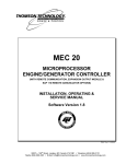
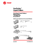
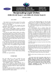
1
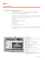
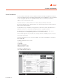
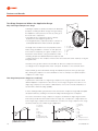
Centrifugal
Water Chillers
Model CVGF
Water-Cooled Hermetic Centrifugal
Refrigeration Capacities from
400 to 1000 Tons (1400 3510 kW)
50 and 60 Hz
October 2008
CTV-PRC001-E4
Introduction
Introducing Trane’s Model CVGF Centrifugal Water Chiller
Introduction
The basic gear driven centrifugal water chiller design was introduced in 1976 and has been proven
in thousands of installations. Trane continues to deliver its reliability and energy fitness commitment
on its newest line of gear-drive centrifugal water chillers, the Model CVGF. The major advantages of
the Model CVGF are:
• High reliability
• Low sound levels
• Compact size
• High efficiency at a competitive market price
• Designed to use environmentally responsible HFC-134a refrigerant
The Model CVGF chiller is ideal for office, hospital, school, hotel, retail store and industrial
buildings. TheTrane centrifugal chiller line offers hundreds of individual evaporator-condensercompressor combination selections, permitting precise tailoring of the machine capacity to
system requirements. Machine selections can be computer optimized to provide low first cost,
low operating cost, or other criteria important for a particular selection. Centrifugal Water Chiller
computer selection program is certified in accordance with ARI Standard 550/590. Trane Sales
Engineers are available to assist in selecting the optimum machine to satisfy the particular project
requirements.
Turn to the Model CVGF for energy efficiency provided by the two stage, gear drive centrifugal
water chillers with economizers. The Trane Model CVGF is your choice for energy fit operation year
after year.
© 2008 Trane, All rights reserved
CTV-PRC001-E4
Contents
Introduction …………………………………………………………………………2
Features and Benefits
……………………………………………………………9
Application Considerations
……………………………………………………10
General Data ………………………………………………………………………12
Jobsite Connections
……………………………………………………………13
Controls ……………………………………………………………………………17
Physical Dimensions
……………………………………………………………19
Mechanical Specifications ………………………………………………………23
Conversion Table …………………………………………………………………27
CTV-PRC001-E4
3
Features and Benefits
Standard CVGF Features
The following features are provided as standard with all Trane Model CVGFchillers:
• Hermetic two-stage centrifugal compressor-motor assembly with integral lubrication system
and economizer cycle
• Evaporator and condenser assembly
• Prewired instrument and control panel
• Oil charge
• Integral oil heaters
• Isolation pads
• Wiring and oil system interconnection to main control panel
• Advance motor protection
• Two-stage gear drive with economized cycle for high efficiency and high reliability
• Liquid cooled hermetic induction motor; the motor operates at lower temperatures for longer
motor life
Optional Features
• Unit and remote wye-delta mounted starters
• Unit mounted, floor mounted, and wall mounted solid state starters.
• Across-the-line, Primary Reactor, and Auto Transformer Remote mounted starter for medium/
high voltage
• Marine waterboxes for evaporator and condenser
• Factory-applied thermal insulation
• One-inch deflection spring isolators for vibration-sensitive installations
• Refrigerant available from a local distributor
• Building automation systems (BAS) Interface
• Factory testing
Applications
• Comfort cooling
• Industrial process cooling
Patents
• Polygon drive for refrigeration compressor impellers
• Centrifugal compressor sump demister
• Internal oil filter
• Thermosiphonic oil cooler
• Compressor height and alignment adjustment
• Oil return using hot gas for motive force
• Centrifugal impeller assembly
• Internal oil filter
Orifice System
• Simplified orifice system with improved part load performance down to 20 percent part load
4
CTV-PRC001-E4
Features and Benefits
Advanced Heat Transfer Surfaces
• Evaporator and condenser tubes use the latest heat transfer surfaces
• Less refrigerant needed due to advanced patented evaporator design
Compact Size
• Designed with the retrofit and replacement market in mind
• The 400 to 500 NTON sizes can fit through most double-width doors
• Small footprint of the CVGF chiller saves valuable equipment room space
Simple Installation
• Simplified piping; the only water piping required is for the evaporator and condenser
• Simple power connection
• Unit mounted starter eliminates additional jobsite labor requirements
Environmental Features and Benefits
Improved Efficiency:
• High Efficiency: 0.55 kW/Ton at ARI conditions
• Motor cooling vented to economizer cycle, efficiency advantage
• HFC-134 optimized inlet guide vanes and impellers for improved cycle efficiency using
computational fluid dynamics
Reduced Emissions:
• Over 30 percent joint reduction in compressor/motor assembly compared to previous designs
• Patented integral heaters imbedded into the compressor casting, no seals no leaks
• Beaded flat gasket technology instead of O-rings, lower susceptibility to developing leaks
• Minimal NPT pipe threads on chiller system, SAE O-ring boss fitting, lowerleak potential
• Oil sump internal to compressor/motor assembly with internal pump/motor; eliminates vent and
drain lines, leak prevention
• Patented internal oil filter prevents leaks and contamination from pipes; filter is isolated and easily
replaced
• Advanced evaporator design minimizes the refrigerant charge; a reduced charge reduces the
exposure to the environment in the event of a catastrophic charge loss
Additional Features and Benefits
• Patented polygon attachment instead of a keyed shaft, self-balancing
• Easy to replace motor terminals
• Motor/stator assembly is easily removed; speed assembly can be removed independent of the
high-speed assembly
• Rolling element bearings
• Hydrodynamic bearings
• Advanced evaporator design: no eliminator necessary with an advanced suction baffle design
• All metric fasteners
CTV-PRC001-E4
5
Features and Benefits
Tracer AdaptiViewTM Control Operator Interface
Tracer AdaptiViewTM control is the unit-mounted operator interface with a touch sensitive 12/1"
display. The display presents information through an intuitive navigation system. Alternate
languages are also available for the control panel display.
Tracer AdaptiViewTM control receives information from and communicates information to the other
devices on the chiller’s communications link. Tracer AdaptiViewTM control performs the Leaving
Chilled Water Temperature and Limit Control algorithms.
• Data graphs
• Mode overrides
• Status (all subsystems) with animated graphics
• Auto/Stop commands
• 50 diagnostics
• ASHRAE chiller log
• Setpoint adjustment (daily user points)
Tracer AdaptiViewTM control can be connected to the service tool using a standard USB type cable.
The connections is located on the side of the control panel, along with a power outlet for a laptop
PC power supply.
h
a At-a-glance status
On highly-readable color display showing key operating parameters of
major chiller components
b Intuitive navigation
Helps operators access data and alarms for quick and accurate
response and resolution
a
c Reports
Summarize data for clear understanding and interpretation
d Graphs
Visualize trend data for troubleshooting and fine-tuning
b
e Adaptive controlTM
Algorithms built into Tracer AdaptiviewTM pre-empt chiller disruptions
during rapidly changing conditions
e
f
f Open protocol flexibility
Bacnet, Lontalk, and Modbus with no gateways
g Adjustable viewing angle
For all operators in close quarters via ergonomic arm
c
d
g
i
j
h Water-resistant
To cleaning overspray; weather-resistant for outdoor mounting with
optional cover
i Security levels
Limit access to designated, qualified staff members
j 24 selectable languages
Convert the Tracer AdaptiviewTM user-centered design for global
deployment including simplified chinese, traditional chinese, japanese,
korean, thai, etc.
6
CTV-PRC001-E4
Features and Benefits
Tracer TU Interface
The Tracer chiller controller adds a level of sophistication better served by a PC application to improve
service technician effectiveness and minimize chiller downtime. Tracer AdaptiView™ control is intended
to serve only typical daily tasks. The portable PC-based service-tool software, Tracer TU™,
supports service and maintenance tasks.
Tracer TU serves as a common interface to all Trane chillers, and will customize itself
based on the properties of the chiller with which it is communicating. Thus, the service technician
learns only one service interface.
The panel bus is easy to troubleshoot using LED sensor verification. Only the defective device is
replaced. Tracer TU can communicate with individual devices or groups of devices.
All chiller status, machine configuration settings, customizable limits, and up to 100 active or
historic diagnostics are displayed through the service-tool software interface.
LEDs and their respective Tracer TU indicators visually confirm the availability of each connected
sensor, relay, and actuator.
Tracer TU is designed to run on a customer’s laptop, connected to the AdaptiView control panel
with a USB cable.
Hardware requirements for Tracer TU:
• CD-ROM
• 1 GB RAM
• 1024 x 768 resolution
• Ethernet 10/100 Lan card
• Windows® XP Pro or Vista
• Pentium IV or higher processor
• An available USB port (USB 2.0)
CTV-PRC001-E4
7
Features and Benefits
Tracer AdaptiViewTM Controller
Today's centrifugal chillers offer predictive controls that anticipate and compensate for load
changes. Other control strategies made possible with the Tracer AdaptiViewTM controls are:
Feedforward Adaptive Control
Feedforward is an open-loop, predictive control strategy designed to anticipate and compensate
for load changes. It uses evaporator entering-water temperature as an indication of load change.
This allows the controller to respond faster and maintain stable leaving-water temperatures.
Soft Loading
The chiller controller uses soft loading except during manual operation. Large adjustments
due to load or setpoint changes are made gradually, preventing the compressor from cycling
unnecessarily. It does this by internally filtering the setpoints to avoid reaching the differential-tostop or the current limit. Soft loading applies to the leaving chilled-water temperature and currentlimit setpoints.
Multi-Objective Limit Arbitration
There are many objectives that the controller must meet, but it cannot satisfy more than one
objective at a time. Typically, the controller’s primary objective is to maintain the evaporator leavingwater temperature.
Whenever the controller senses that it can no longer meet its primary objective without triggering
a protective shutdown, it focuses on the most critical secondary objective. When the secondary
objective is no longer critical, the controller reverts to its primary objective.
Fast Restart
The controller allows the CenTravac chiller to restart during the postlube process. If the chiller shuts
down on a nonlatching diagnostic, the diagnostic has 30–60 seconds to clear itself and initiate a
fast restart. This includes momentary power losses.
Building Automation and Chiller Plant Control
Trane Tracer SummitTM building automation systems
include pre-engineered and flexible control for
chiller plants. It can control the operation of the
complete installation: chillers, pumps, cooling
towers, isolating valves, air handlers and terminal
units.Trane can undertake full responsibility for an
optimized automation and energy management
for the entire chiller plant.
The main functions are:
• Chiller sequencing: equalizes the number of
running hours of the chillers. Different control
strategies are available depending on the
configuration of the installation.
• Control of the auxiliaries: includes input/output
modules to control the operation of the various
auxiliary equipments (water pumps, valves,
cooling towers, etc.)
8
CTV-PRC001-E4
Features and Benefits
• Time of day scheduling: allows the end user to define the occupancy period, i.e. time of the
day, holiday periods and exception schedules.
• Optimization of the start/stop time of the installation: based on the programmed schedule
of occupancy and on the historical temperature records, Tracer SummitTM calculates the optimal
start/stop time of the installation to get the best compromise between energy savings and
comfort of the occupants.
• Soft loading: the soft loading function minimizes the number of chillers that are operated to
satisfy a large chilled-water-loop pull down, thus preventing an overshoot of the actual capacity
required. Unnecessary starts are avoided and the peak current demand is lowered.
• Communication capabilities: local, through a PC workstation keyboard Tracer SummitTM
can be programmed to send messages to local or remote workstations and or a pager in the
following cases:
—Analog parameter exceeding a programmed value.
—Maintenance warning.
—Component failure alarm.
—Critical alarm messages. In this latter case, the message is displayed until the operator
acknowledges the receipt of the information. From the remote station it is also possible to
access and modify the chiller plant’s control parameters.
• Remote communication through a modem: As an option, a modem can be connected to
communicate the plant operation parameters through voice grade phone lines.
The remote terminal is a PC workstation equipped with a modem and software to display the
remote plant parameters.
Chiller-Tower Optimization
Tracer Summit™ chiller-tower optimization extends Adaptive Control™ to the rest of the chiller
plant. Chiller-tower optimization is a unique control algorithm for managing the chiller and coolingtower subsystem. It considers the chiller load and real-time ambient conditions, then optimizes the
tower setpoint temperature to maximize the efficiency of the subsystem.
Integrated Comfort™ System (ICS)
The onboard Tracer chiller controller is designed to be able to communicate with a wide range of
building automation systems. To take full advantage of the capabilities of the chiller, incorporate
your chiller into a Tracer Summit building automation system.
But the benefits do not stop at the chiller plant. At Trane, we realize that all energy used in your
cooling system is important. That is why we worked closely with other equipment manufacturers
to predict the energy required by the entire system. We used this information to create patented
control logic for optimizing the HVAC system efficiency.
The building owner’s challenge is to tie components and applications expertise into a single
reliable system that provides maximum comfort, control and efficiency. Trane’s Integrated-Comfort
™ Systems (ICS) are a concept that combines system components, controls and engineering
applications expertise into a single, logical and efficient system. These advanced controls are fully
commissioned and available on every piece of Trane equipment, from the largest chiller to the
smallest VAV box. As a manufacturer, only Trane offers this universe of equipment, controls and
factory installation and verification.
CTV-PRC001-E4
9
Features and Benefits
Two-Stage Compressor Widens the Application Range
Why Centrifugal Compressors Surge
Centrifugal compressors produce their pressure differential
(head) by converting the kinetic energy of the gas leaving
the impeller into static pressure. The velocity of this gas is
the result of two components:
• The radial velocity component Vr, which is directly
proportional to the refrigerant gas flow Q.
• The tangential velocity component Vt,which is a function of
both impeller diameter D and the rotational speed rpm.
1 - Vr = f (Q)
The length of the resultant vector V is proportional to the
2 - Vt = f (D, RPM)
3 - V = Resultant
kinetic energy available for conversion to static pressure
4 - rpm
in the volute. Consequently, for a given compressor, Vt is
5-D
fixed and Vr varies with the cooling load. With the chiller
6-Q
unloading, the pressure differential between evaporator and
condenser decreases. The compressor matches the new load and the lower “head” by closing the
inlet guide vanes.
This reduces the gas flow it draws in and modifies its direction. Component Vr decreases
accordingly, the vector diagram shifts and at some point, the balance of forces breaks down.
As pressurized gas rushes backwards through the impeller, the pressure in the gas passages
falls, allowing the compressor to restore the balance of forces. If the process repeats itself, the
compressor is said to surge.
Two-Stage Compressors Surge Less and Later
To produce the same head as a single-stage compressor, two-stage machines use two small
diameter impellers. Component Vt is the same as on each stage, though Vr is the same as on a
single-stage compressor. This results in a better balance of forces at low loads and produces a
machine with a wider unloading capability.
In Trane centrifugal chillers, gas prerotation vanes ahead of the compression stage improve impeller
aerodynamic efficiency, resulting in smoother unloading and reducing power consumption.
The curves show that two-stage compressors surge less and later than single-stage machines.
Intersection point B, when the load line meets the surge area, corresponds to a higher part load
for the single-stage compressor than would be the case with a two-stage compressor. Two stage
machines, therefore, have a wider range of applications.
1 - Load Line
2 - Surge Line
3-A
4-B
5 - 40%
6 - 90° Vanes
7 - 100%
8 - Compressor Head
9 - Refrigerant Gas Flow
Typical single-stage compressor
performance curve
10
Typical two-stage compressor
performance curve
1 - Load Line
2 - Surge Line
3-A
4-B
5 - 20%
6 - 90°
7 - 80°
8 - 70° Vanes
9 - 100%
10 - Compressor Head
11 - Refrigerant Gas Flow
CTV-PRC001-E4
Application Considerations
Condenser Water Limitations
Temperature
Trane centrifugal chillers start and operate over a range of load conditions with controlled water
temperatures. Reducing the condenser water temperature is an effective method of lowering the
chiller power input. However, the effect of lowering the condenser water temperature may cause an
increase in system power consumption.
In many applications Trane centrifugal chillers can start and operate without control of the
condenser water temperature. However, for optimum system power consumption, and for
any applications with multiple chillers, control of the condenser water circuit is recommended.
Integrated control of the chillers, pumps, and towers is easily accomplished with Trane’s AdaptiView
and/or Tracer system.
Chillers are designed to ARI conditions of 29.4°C (85°F), but Trane centrifugal chillers can operate
to a five psig pressure differential between the condenser and evaporator at any steady state load
without oil loss, oil return, motor cooling, or refrigerant hang-up problems. And this differential
can equate to safe minimum entering condenser water temperatures at or below 12.8°C (55°F),
dependent on a variety of factors such as load, leaving evaporator temperature, and component
combinations. Startup below this differential is possible as well, especially with AdaptiView soft start
features
Water Pumps
Avoid specifying or using 3600-rpm condenser and chilled water pumps. Such pumps may operate
with objectionable noises and vibrations. In addition, a low frequency beat may occur due to the slight
difference in operating rpm between water pumps and centrifugal motors. Where noise and vibrationfree operation are important, Trane encourages the use of 1750 rpm pumps.
Water Flow
Today’s technology challenges ARI’s traditional design of three gpm per ton through the condenser.
Reduced condenser flows are a simple and effective way to reduce both first and operating costs
for the entire chiller plant. This design strategy will require more effort from the chiller, but pump
and tower savings will typically offset any penalty. This is especially true when the plant is partially
loaded or condenser relief is available.
In new systems, the benefits can include dramatic savings with:
• Size and cost for condenser lines and valves
• Size and cost of the cooling tower
• Size and cost of the water pumps
• Pump energy (30% to 35% reduction)
• Tower fan energy(30% to 35% reduction)
Replacement chiller plants can reap even greater benefits from low-flow condensers. Because
the water lines and tower are already in place, reduced flows would offer a tremendous energy
advantage. Theoretically, a 2 gpm/ton design applied to a system that originally used 3 gpm/ton
would offer a 70% reduction in pump energy. At the same time, the original tower would require a
nozzle change but would then be able to produce about two degrees colder condenser water than
before. These two benefits would typically offset any extra effort required by the chiller.
CTV-PRC001-E4
11
Application Considerations
Contact your local Trane Sales Office for information regarding optimum condenser water
temperatures and flow rates for a specific application.
Water Treatment
The use of untreated or improperly treated water in a chiller may result in scaling, erosion, corrosion,
algae, or slime. It is recommended that the services of a qualified water treatment specialist are
used to determine what treatment, if any, is advisable. Trane assumes no responsibility for the
results of untreated or improperly treated water.
12
CTV-PRC001-E4
General Data
Table GD-1 – Model CVGF Description
Model
CVGF
Nominal Cooling Capacity
NTON
Heat Exchanger Size
Evaporator
EVSZ
Condenser
CDSZ
Heat Exchanger Bundles
Evaporator
EVBS
Condenser
CDBS
Heat Exchanger Tube
Evaporator
EVTM
CDTM
Evap/Cond Working Pressure
bar
psi
Evap/Cond Water Connection
400
500
500
650
800
1000
500
500
500
500
700
700
700
700
1000
1000
1000
1000
A = Small
B = Medium
C = Large
A = Small
B = Medium
C = Large
A = Small
B = Medium
C = Large
A = Small
B = Medium
C = Large
A = Small
B = Medium
C = Large
A = Small
B = Medium
C = Large
A = Small
B = Medium
C = Large
A = Small
B = Medium
C = Large
A = Small
B = Medium
C = Large
D = Extra Large
A = Small
B = Medium
C = Large
D = Extra Large
A = Small
B = Medium
C = Large
D = Extra Large
A = Small
B = Medium
C = Large
D = Extra Large
IE25 - 0.635 mm W 25.4 mm Internally Enhanced
(IE25 - 0.025” W 1.00” Internally Enhanced)
TE25 - 0.635 mm W19 mm Internally Enhanced
(TE25 - 0.025” W 0.75” Internally Enhanced)
IE28 - 0.711 mm W 25.4 mm Internally Enhanced
(IE28 - 0.028” W 1.00” Internally Enhanced)
TE28 - 0.711 mm W 19 mm Internally Enhanced
(TE28 - 0.028” W 0.75” Internally Enhanced)
10
150
Grooved Pipe Connections
Flanged Adaptor (IP Unit)
Flanged Adaptor (SI Unit)
Agency Approvals (Chiller)
UL-CUL Listed/ASME
CE Approval/PED (European Code)
Motor Volt/Hz
380/400/415/3300/6600 Volts – 50 Hz
380/460/575/3300/4160 Volts – 60 Hz
Starter*
Unit Mounted
Remote Mounted
Wye-Delta, Solid-State Inside the Delta
Wye-Delta, Solid-State Inside the Delta, *Across-the-line, *Primary Reactor, *Autotransformer
*Medium Voltage (3300, 4160, 6600) Starter Types - Full Voltage (X-Line), Primary Reactor, Autotransformer
Table GD-2 – Weight
Without Starter
With Starter
Shell Size
Operating
Shipping
Operating
Shipping
Model Compressor Evaporator Condenser
lbs
kgs
lbs
kgs
lbs
kgs
lbs
kgs
CVGF
400 - 500
500
500
23288
10563
20570
9331
23856
10821
21142
9590
CVGF
500
700
700
28052
12725
24174
10965
28623
12984
24743
11223
CVGF
650
700
700
29508
13383
25635
11628
30105
13656
26058
11820
CVGF
800
1000
1000
40285
18273
34229
15526
40924
18563
34868
15816
CVGF
1000
1000
1000
41202
18689
35114
15941
41843
18980
35785
16232
**Note: Values represent estimate maximum unit weights including shells with TECU tubes, max bundles, 2-pass evaporator and condenser, 150
psig non-marine waterboxes, and compressors with the largest low-voltage motors for each family.
CTV-PRC001-E4
13
General Data
50 and 60 Hz SI Units and (English Units)
Table GD-3 –Evaporator and Condenser Flow Rates (Minimum and Maximum, liters per second, gallons per minute)
High Efficiency Shells - 0.75 inch (19 mm) Internally Enhanced Cu Tube:
Condenser:
Nominal Shell
Bundle Size
500
500
500
700
700
700
1000
1000
1000
1000
Small
Medium
Large
Small
Medium
Large
Small
Medium
Large
Extra Large
Number of Passes
2
2
2
2
2
2
2
2
2
2
Min Flow L/s (gpm)
31 (487)
34 (542)
37 (586)
42 (668)
47 (744)
52 (816)
59 (938)
67 (1056)
74 (1176)
77 (1213)
Max Flow L/s (gpm) 113 (1786) 125 (1987) 136 (2148) 155 (2450) 172 (2727) 189 (2993) 217 (3441) 244 (3874) 272 (4311) 280 (4447)
Evaporator:
Nominal Shell
Bundle Size
500
500
500
700
700
700
1000
1000
1000
1000
Small
Medium
Large
Small
Medium
Large
Small
Medium
Large
Extra Large
Number of Passes
2
2
2
2
2
2
2
2
2
2
Min Flow L/s (gpm)
26 (407)
29 (458)
32 (511)
36 (566)
40 (628)
44 (698)
52 (822)
58 (921)
64 (1021)
72 (1136)
Max Flow L/s (gpm)
94 (1493) 106 (1680) 118 (1873) 131 (2077) 145 (2304) 161 (2559) 190 (3013) 213 (3377) 236 (3745) 263 (4165)
Evaporator:
Nominal Shell
Bundle Size
500
500
500
700
700
700
1000
1000
1000
1000
Small
Medium
Large
Small
Medium
Large
Small
Medium
Large
Extra Large
Number of Passes
3
3
3
3
3
3
3
3
3
3
Min Flow L/s (gpm)
17 (271)
19 (305)
21 (340)
24 (378)
26 (419)
29 (465)
35 (548)
39 (614)
43 (681)
48 (757)
Max Flow L/s (gpm)
63 (995)
71 (1120)
79 (1248)
87 (1385)
97 (1536) 108 (1706) 127 (2009) 142 (2251) 158 (2497) 175 (2777)
Standard Efficiency Shells - 1.00 inch (25.4 mm) Int. Enhanced Cu Tube:
Condenser:
Nominal Shell
Bundle Size
500
500
500
700
700
700
1000
1000
1000
1000
Small
Medium
Large
Small
Medium
Large
Small
Medium
Large
Extra Large
Number of Passes
2
2
2
2
2
2
2
2
2
2
Min Flow L/s (gpm)
31 (499)
35 (557)
38 (606)
43 (682)
48 (764)
53 (838)
58 (925)
64 (1020)
75 (1172)
83 (1307)
Max Flow L/s (gpm) 115 (1831) 129 (2041) 140 (2221) 158 (2501) 177 (2801) 194 (3071) 214 (3391) 236 (3741) 276 (4372) 302 (4792)
Evaporator:
Nominal Shell
Bundle Size
500
500
500
700
700
700
1000
1000
1000
1000
Small
Medium
Large
Small
Medium
Large
Small
Medium
Large
Extra Large
2
2
Number of Passes
2
2
2
2
2
2
2
Min Flow L/s (gpm)
28 (447)
31 (496)
35 (550)
39 (625)
45 (706)
49 (784)
49 (781)
2
236 (3741) 63 (1003)
70 (1115)
Max Flow L/s (gpm) 103 (1638) 115 (1818) 127 (2018) 145 (2293) 181 (2874) 181 (2874) 181 (2864) 207 (3287) 232 (3678) 258 (4090)
Evaporator:
Nominal Shell
Bundle Size
500
500
500
700
700
700
1000
1000
1000
1000
Small
Medium
Large
Small
Medium
Large
Small
Medium
Large
Extra Large
Number of Passes
3
3
3
3
3
3
3
3
3
3
Min Flow L/s (gpm)
19 (298)
21 (330)
23 (367)
26 (417)
30 (471)
33 (523)
33 ((521)
38 (598)
42 (669)
47 (744)
Max Flow L/s (gpm)
69 (1092)
76 (1212)
85 (1346)
96 (1529) 109 (1726) 121 (1916) 120 (1909) 138 (2191) 15 (2452)
14
172 (2726)
CTV-PRC001-E4
Jobsite Connections
Supply and Motor Lead Wiring and Connections
Only copper conductors should be connected to the compressor motor due to the possibility of
galvanic corrosion as a result of moisture if aluminum conductors are used. Copper conductors are
recommended for supply leads in the starter panel.
Suggested starter panel line- and load-side lug sizes (when lugs are provided) are noted in the
starter submittals. These submitted lug sizes should be carefully reviewed for compatibility with
conductor sizes specified by the electrical engineer or contractor. If they are not compatible, the
electrical engineer or contractor should specify the required lug sizes for the particular application.
Ground lugs are provided in the motor terminal box and starter panel. The motor terminals are
supplied with connection pads that will accommodate bus bars or standard terminal lugs (crimp
type recommended). Terminal lugs are field-supplied. These connection pads provide additional
surface area to minimize improper electrical connections. Also, a 3/8-inch bolt is provided on all
connection pads for mounting the lugs. Figure J-1 illustrates the connection between the motor
connection pads and the terminal lugs.
Figure J-1 — Electric Connections
Shipment and Assembly
All style hermetic centrifugal units ship as a factory assembled, factory tested package, ready to rig
into place on factory supplied isolation pads.
CTV-PRC001-E4
15
Controls
Standard Features
Standard Features
Field Connection
The field-connected elements are involved in physically turning the chiller on or off. This involves
ensuring that the chiller is not in an emergency or external stop condition, starting the pumps, and
verifying that flow has been established. The optional, factory-supplied flow switch or a customersupplied differential-pressure switch can be used to prove flow.
Heat Exchanger Control
Fundamental internal variables that are necessary to control the chiller are gathered and acted
upon by the heat exchanger control function.
Motor Control and Compressor Protection
This includes all functions that start, run, and stop the motor. The starter module provides the
interface and control of Y-delta, across-the-line, primary reactor, autotransformer, and solid-state
starters. The motor control also provides protection to both the motor and the compressor.
Phase Voltage Sensors – 3 phase
Includes factory-installed potential/current transformers in the starter for monitoring and displaying
phase voltage and provides over/undervoltage protection. Tracer AdaptiViewTM control, Tracer TU
and Tracer Summit display the following:
• Compressor phase amperage (a-b, b-c, c-a)
• Kilowatts
• Power factor (uncorrected)
• Compressor-phase voltage (a-b, b-c, c-a)
• Kilowatt-hours
Chilled-Water Reset
Chilled-water reset reduces energy consumption during periods of the year when heating loads are
high and cooling loads are reduced. It is based on return chilled-water temperature. Resetting the
chilled-water temperature reduces the amount of work that the compressor must do by increasing
the evaporator refrigerant pressure. This increased evaporator pressure reduces the pressure
differential the compressor must generate while in the heat recovery mode. Chilled-water reset is
also used in combination with the hot-water control. By resetting the chilled-water temperature
upward, the compressor can generate a higher condenser pressure, resulting in higher leaving hotwater temperatures.
16
CTV-PRC001-E4
Controls
Optional Features
Extended Operation Package
Select the extended-operation package for chillers that require external, hot water control, and/or
base-loading capabilities. This package also includes a 4-20 mA or 0-10 Vdc analog input for a
refrigerant monitor.
• External base-loading control
• External base-loading relay
• External hot-water control relay
• Refrigerant monitor input
Base-Loading Control
This feature allows an external controller to directly modulate the capacity of the chiller. It is typically
used in applications where virtually infinite sources of evaporator load and condenser capacity are
available and it is desirable to control the loading of the chiller. Two examples are industrial process
applications and cogeneration plants. Industrial process applications might use this feature to
impose a specific load on the facility’s electrical system. Cogeneration plants might use this feature
to balance the system’s heating, cooling, and electrical generation.
All chiller safeties and Adaptive Control functions are in full effect when Base Loading is enabled.
If the chiller approaches full current, the evaporator temperature drops too low, or the condenser
pressure rises too high, the controller’s Adaptive Control logic limits the loading of the chiller to
prevent the chiller from shutting down on a safety limit. These limits may prevent the chiller from
reaching the load requested by the Base Loading signal.
An alternative and less radical approach to Base Loading indirectly controls chiller capacity.
Artificially load the chiller by setting the chilled-water setpoint lower than it is capable of achieving.
Then, modify the chiller’s load by adjusting the current-limit setpoint. This approach provides
greater safety and control stability because it leaves the chilled-water temperature-control logic in
effect. The chilled-water temperature control responds more quickly to dramatic system changes
and limits chiller loading prior to reaching an Adaptive Control limit.
Hot-Water Control
This feature allows an external controller to enable/disable and modulate the hot-water control
mode. Occasionally, centrifugal chillers are used to provide heating as a primary mission. In this
case the external controller or operator would select a hot-water temperature setpoint and the
chiller capacity would be modulated to maintain the setpoint. Heating is the primary mission and
cooling is a waste product or a secondary mission. This technique provides application flexibility,
especially in multiple-chiller plants in conjunction with undersized heating plants.
The chiller needs only one condenser for hot-water control, whereas Heat Recovery uses a
secondary condenser.
Refrigerant Monitor
The Extended Operation package allows for a refrigerant monitor to send a 4-20 mA signal to
the Tracer AdaptiViewTM control display. It can be calibrated to correspond to either 0-100 ppm
or 0-1,000 ppm concentration levels. The concentration level is displayed at Tracer AdaptiViewTM
control, but the chiller will not take any action based on the input from the refrigerant monitor.
Alternatively, a refrigerant monitor can be connected to Tracer Summit, which has the ability to
increase ventilation in the equipment room in response to high refrigerant concentrations.
CTV-PRC001-E4
17
Controls
Standard Protections
Standard Protections
The chiller controller uses proportional-integral-derivative (PID) control for all limits—there is no
dead band. This removes oscillation above and below setpoints and extends the capabilities of the
chiller.
Some of the standard protection features of the chiller controller are described in this section. There
are additional protection features not listed here. Contact your local Trane office for additional
protection information.
High Condenser-Pressure Protection
The chiller controller’s condenser limit keeps the condenser pressure under a specified maximum
pressure. The chiller will run up to 100 percent of this setpoint before the Adaptive Control mode
reduces capacity.
Starter-Contactor Failure Protection
The chiller will protect itself from a starter failure that prevents the compressor motor from
disconnecting from the line to the limits of its capabilities.
The controller starts and stops the chiller through the starter. If the starter malfunctions and does
not disconnect the compressor motor from the line when requested, the controller will recognize
the fault and attempt to protect the chiller by operating the evaporator-and condenser-water
pumps and attempting to unload the compressor.
Loss of Water-Flow Protection
Tracer AdaptiViewTM control has an input that will accept a contact closure from a proof-of-flow
device such as a flow switch or pressure switch. Customer wiring diagrams also suggest that the
flow switch be wired in series with the cooling-water (condenser-water) pump starter’s auxiliary
contacts. When this input does not prove flow within a fixed time during the transition from Stop to
Auto modes of the chiller, or if the flow is lost while the chiller is in the Auto mode of operation, the
chiller will be inhibited from running by a nonlatching diagnostic.
Evaporator Limit Protection
Evaporator Limit is a control algorithm that prevents the chiller tripping on its low refrigeranttemperature cutout. The machine may run up to the limit but not trip. Under these conditions the
intended chilled-water setpoint may not be met, but the chiller will do as much as it can. The chiller
will deliver as much cold water as possible even under adverse conditions.
Low Evaporator-Water Temperature
Low evaporator-water temperature protection, also known as Freeze Stat protection, avoids water
freezing in the evaporator by immediately shutting down the chiller and attempting to operate the
chilled-water pump. This protection is somewhat redundant with the Evaporator Limit protection,
and prevents freezing in the event of extreme errors in the evaporator-refrigerant temperature
sensor.
The cut out setting should be based on the percentage of antifreeze used in the customer's water
loop. The chiller’s operation and maintenance documentation provides the necessary information
for percent antifreeze and suggests leaving-water temperature-cutout settings for a given chilledwater temperature setpoint.
18
CTV-PRC001-E4
Controls
Standard Protections
Oil-Temperature Protection
Low oil temperature when the oil pump and/or compressor are running may be an indication of
refrigerant diluting the oil. If the oil temperature is at or below the low oil-temperature setpoint,
the compressor is shut down on a latching diagnostic and cannot be started. The diagnostic
is reported at the user interface. The oil heaters are energized in an attempt to raise the oil
temperature above the low oil-temperature setpoint.
High oil-temperature protection is used to avoid overheating the oil and the bearings.
Low Differential Oil-Pressure Protection
Oil pressure is indicative of oil flow and active oil-pump operation. A significant drop in oil pressure
indicates a failure of the oil pump, oil leakage, or a blockage in the oil-circuit.
During Compressor prelube the differential pressure should not fall below 12 psid. Shutdown
diagnostic will occure within 2 seconds of the differential pressure falling below two-thirds of the
low differential oil-pressure cutout.
Phase-Unbalance Protection
Phase-unbalance protection is based on an average of the three phase-current inputs. The ultimate
phase-unbalance trip point is 30 percent. In addition, the RLA of the motor is derated by resetting
the active current-limit setpoint based on the current unbalance. The RLA derate protection can be
disabled in the field-startup menu.
The following derates apply when the phase-unbalance limit is enabled:
10% unbalance = 100% RLA derate
15% unbalance = 90% RLA derate
20% unbalance = 85% RLA derate
25% unbalance = 80% RLA derate
30% unbalance = Shutdown
Phase-Loss Protection
The controller will shut down the chiller if any of the three phase currents feeding the motor drop
below 10 percent RLA. The shutdown will result in a latching phase-loss diagnostic. The time to
trip is 1-3 seconds.
Phase Reversal/Rotation Protection
The controller detects reverse phase rotation and provides a latching diagnostic when it is
detected. The time to trip is 0.7 seconds.
Momentary Power Loss and Distribution Fault Protection
Three-phase momentary power loss (MPL) detection gives the chiller improved performance
through many different power anomalies. MPLs of 2.5 cycles or longer will be detected and cause
the unit to shut down. The unit will be disconnected from the line within 6 line cycles of detection.
If enabled, MPL protection will be active any time the compressor is running. MPL is not active on
reduced-voltage starters during startup to avoid nuisance trips. The MPL diagnostic is an automatic
reset diagnostic.
An MPL has occurred when the motor no longer consumes power. An MPL may be caused by any
drop or sag in the voltage that results in a change in the direction of power flow. Different operating
conditions, motor loads, motor size, inlet guide vane (IGV) position, etc. may result in different
CTV-PRC001-E4
19
Controls
Standard Protections
levels at which this may occur. It is difficult to define an exact voltage sag or voltage level at which a
particular motor will no longer consume power, but we are able to make some general statements
concerning MPL protection:
The chiller will remain running under the following conditions:
• Line-voltage sag of 1.5 line cycles or less for any voltage magnitude sag
• Control-voltage sags of less than 3 line cycles for any magnitude sag
• Control-voltage sags of 40 percent or less for any amount of time
• Second-order or lower harmonic content on the line
The chiller may shut down under the following conditions:
• Line-voltage sags of 1.5 or more line cycles for voltage dips of 30 percentor more
• Control-voltage sags of 3 or more line cycles for voltage dips of 40 percentor more
• Third-order or higher harmonic content on the line
Current Overload Protection
The control panel will monitor the current drawn by each line of the motor and shut the chiller
off when the highest of the three line currents exceeds the trip curve. A manual reset diagnostic
describing the failure will be displayed. The current overload protection does not prohibit the chiller
from reaching its full-load amperage.
The chiller protects itself from damage due to current overload during starting and running modes,
but is allowed to reach full-load amps.
High Motor-Winding Temperature Protection
This function monitors the motor temperature and terminates chiller operation when the
temperature is excessive. The controller monitors each of the three winding-temperature sensors
any time the controller is powered up, and displays each of the temperatures at the service menu.
Immediately prior to start, and while running, the controller will generate a latching diagnostic if the
winding temperature exceeds 265°
F(129.4℃) for 0.5 to 2 seconds.
Surge Detection Protection
Surge detection is based on current fluctuations in one of three phases. The default detection
criterion is two occurrences of root-man square (RMS) current change of 30 percent within 0.8
seconds in 60 + 10 percent seconds. With the Tracer chiller controller, the detection criterion is
adjustable with the Tracer chiller controller.
Overvoltage and Undervoltage Protection
While some components of the chiller are impervious to dramatically different voltages, the
compressor-motor is not. The control panel monitors all three line-to-line voltages for the chiller,
and bases the over and undervoltage diagnostics on the average for the three voltages. The default
protection resets the unit if the line voltage is below or above ±10 percent of the nominal for 60
seconds.
Power Factor and kW Measurement
Three-phase measurement of kW and unadjusted power factor yields higher accuracy during
power imbalance conditions.
20
CTV-PRC001-E4
Controls
Standard Protections
Short-Cycling Protection
This function mimics heat dissipation from a motor start using two setpoints:
Restart Inhibit Free Starts and Restart Inhibit Start-to-Start Timer. This allows the CVGF to
inhibit too many starts in a defined amount of time while still allowing for fast restarts. The
default for CVGF is 3 Free Starts and a 20 minute Start-to-Start Timer. The control panel
generates a warning when the chiller is inhibited from starting by this protection.
Restart Inhibit Free Starts
This setting will allow a maximum number of rapid restarts equal to its valve. If the number of
free starts is set to 1, this will allow only one start within the time period set by the Start-to-Start
Time setting. The next Start will be allowed only after the Start-to-Start timer has expired. If the
number of free starts is programmed to 3, the control will allow three starts in rapid succession,
but thereafter, it would hold off on a compressor start until the Start-to-Start timer expired.
Restart Inhibit Start-to-Start Time setting
This setting defines the shortest chiller cycle period possible after the free starts have been
used. If the number of free Starts is programmed to 1, and the Start-to-Start Time setting is
programmed to 10 minutes. the compressor will be allowed one start every 10 minutes The
Start-to-Start time is the time from when the motor was directed to energize to when the next
prestart is issued.
CTV-PRC001-E4
21
Physical Dimensions
50 and 60 Hz SI (English Units)
Figure PD-1 –Model CVGF Cooling Only
Figure PD-2 –Model CVGF Cooling Only Without Unit-Mounted
With Unit-Mounted Starter
Starter (for Remote-Mounted Starter)
Dimensions – SI Units (English Units)
Clearance
Tube Pull
Unit Dimensions
Unit Dimensions
With Unit Mounted Starters
Without Unit Mounted Starters
Comp
Shell Size
CL1
CL2
Length
Height
Width
Width
400-500
500
4235 mm
1118 mm
4083 mm
2094 mm
1984 mm
1929 mm
(13' 10 3/4")
(3' 8")
(13' 4 3/4")
(6' 101/2")
(6' 6 1/8")
(6' 3 15/16")
500
700
4235 mm
1850 mm
4083 mm
2200 mm
2038 mm
1988 mm
13' 10 3/4")
(3' 11")
(13' 4 3/4")
(7' 2 5/8")
(6' 8 1/4")
(6' 6 1/4")
650
700
4235 mm
1850 mm
4083 mm
2270 mm
2083 mm
2076 mm
13' 10 3/4")
(3' 11")
(13' 4 3/4")
(7' 5 3/8")
(6' 10")
(6' 9 3/4")
4235 mm
1219 mm
4083 mm
2521 mm
2305 mm
2257 mm
13' 10 3/4")
(4')
(13' 4 3/4")
(8' 3 1/4")
(7' 6 3/4")
(7' 4 7/8")
800-1000
1000
CL1 at either end of machine and is required for tube pull clearance.
CL2 is always at the opposite end of machine from CL1 and is for water box plus clearance.
– Recommended clearance (D1) for machine with unit mounted starter is 914 mm (36”)
– Recommended clearance (D2) for machine without unit mounted starter is 1219 mm (38”)
Unit length is not included for the waterbox.
See page 23 for waterbox dimension
22
CTV-PRC001-E4
Physical Dimensions
Model CVGF Water Connection Pipe Size
Shell Size
500
700
Water Passes
1000
Metric Pipe Size (mm) DN
Evaporator
2 Pass
DN 200 (8”)
DN 250 (10”)
DN 300 (12”)
3 Pass
DN 200 (8”)
DN 200 (8”)
DN 250 (10”)
Condenser
DN 250 (10”)
DN 300 (12”)
DN 350 (14”)
Condenser
Evaporator Water Box Length — SI (I-P)
Length
No.
Shell
500
700
1000
mm (in)
Pressure
Evap.
Passes
Supply
Return
10 bar (150 psig)
NMAR
2
402 (15.82)
226 (8.89)
10 bar (150 psig)
NMAR
3
402 (15.82)
402 (15.82)
10 bar (150 psig)
NMAR
2
489 (19.25)
235 (9.25)
10 bar (150 psig)
NMAR
3
438 (17.24)
438 (17.24)
10 bar (150 psig)
NMAR
2
581 (22.87)
276 (10.87)
10 bar (150 psig)
NMAR
3
530 (20.87)
530 (20.87)
No.
mm (in)
Condenser Water Box Length — SI (I-P)
Length
Shell
Pressure
Evap.
Passes
Supply
Return
500
10 bar (150 psig)
NMAR
2
486 (19.02)
204 (8.03)
700
10 bar (150 psig)
NMAR
2
582 (22.87)
231 (9.09)
1000
10 bar (150 psig)
NMAR
2
658 (25.75)
276 (10.87)
CTV-PRC001-E4
23
Mechanical Specifications
Trane CVGF packaged centrifugal water chillers using HFC-134a refrigerant consist of a hermetic
two-stage, gear-drive centrifugal compressor, evaporator, condenser, interstage economizer, unitmounted microprocessor based control panel and compressor motor starter. The chiller is entire
factory assembled.
Compressor
Two-stage centrifugal compressor with high-strength aluminum alloy, fully shrouded impellers.
The impellers are tested at 25 percent over-design operating speed. The rotating assembly is
dynamically balanced for vibration of less than 5.1 mm/s (0.2 ips peak velocities) at nominal
operating speeds. The control system affords and admitted 100 - 20 percent capacity modulation
by electrically actuated guide vanes upstream of each impeller.
Drive Train
The drive train consists of helical bull and pinion gears. Gear tooth surfaces are case hardened
and precision ground. The one-piece impeller shaft is supported by hydrodynamic thrust and radial
bearings.
Motor
The motor is a hermetic, liquid-refrigerant cooled, two-pole, low-slip, squirrel-cage induction
motor. A radial hydrodynamic bearing and duplex angular contact ball bearings support the rotor
assembly. Winding-embedded sensors provide positive thermal protection.
Lubrication System
The lubrication system consists of an internal oil sump with heaters, positive displacement oil
pump, brazed plate condenser-cooled oil cooler, and oil distillation/return line.
Economizer/Orifice
The economizer consists of a carbon steel shell with internal components designed to prevent
liquid carryover to the compressor. Liquid refrigerant is admitted through a single calibrated orifice
(no moving parts) which maintains a pressure differential between condenser and economizer.
Evaporator
The evaporator is designed, tested and stamped in accordance with ASME Boiler and Pressure
Vessel Code or PED (European Code) for refrigerant side working pressure of 15.2 bars (220psig).
It consists of a carbon steel shell with steel tube sheets welded to eachend. Intermediate tube
support sheets positioned along the shell axis prevent relative tube motion. Individually-replaceable
externally-finned and internally-grooved 19 mm (¾ in.) and 25.4 mm (1.0 in.) nominal diameter
seamless copper tubes are mechanically expanded into tube sheets.
Two- or three- pass water boxes rated at 10.5 bar (150 psi) is standard. Grooved pipe connections
are standard; flanged connections are optionally available. The waterside is hydrostatically tested at
ASME 1.5 times, PED 1.43 times, GB 1.25 times maximum working pressure.
Liquid refrigerant is admitted to the evaporator through a single calibrated orifice (no moving parts)
which maintains a pressure differential between the economizer and the evaporator.
24
CTV-PRC001-E4
Mechanical Specifications
Condenser
The condenser is designed, tested and stamped in accordance with the ASME Boiler and Pressure
Vessel Code or PED (European Code) for a refrigerant side working pressure of 15.2 bars (220
psig). It consists of a carbon steel shell with steel tube sheets welded to each end. Individuallyreplaceable, externally-finned and internally-grooved 19 mm(¾ in.) and 25.4 mm (1.0 in.) nominal
diameter seamless copper tubes are mechanically expanded into the tubesheets.
Two-pass water boxes are bolted to the tube sheets. Grooved pipe connections are standard.
flanged connections are optionally available. Maximum waterside working pressureof 10.5 bars (150
psi) is standard. The waterside is hydrostatically tested at ASME 1.5 times, PED 1.43 times, GB 1.25
times maximum working pressure.
Unit Control Panel
The microcomputer control panel is factory installed and tested on the CVGF unit. All controls
necessary for the safe and reliable operation of the chiller are provided including oil management,
interface to the starter, and three phase motor overload protection. It also includes comprehensive
status and diagnostic monitoring controls. A control power transformer included in the starter panel
powers the control system.
The microprocessor controller is compatible with reduced voltage or full voltage electro-mechanical
starters, and solid state starter. Starter for Europe with the CE mark is available.
The microcomputer control system processes the leaving evaporator fluid temperature sensor
signal to satisfy the system requirements across the entire load range.
The controller will load and unload the chiller via control of the stepper- motor/actuator which drives
the inlet guide vanes open and closed. The load range can be limited either by a control limitor or
by an inlet guide vane limit (whichever controls the lower limit). It will also control the evaporator
and condenser pumps to insure proper chiller operation.
Status and 10 active diagnostics are communicated to the operator via display with a tabbed
navigation system. Setpoints are entered through the touch-sensitive screen. Countdown timer
displays remaining time(s) during wait states and time out periods. Non-volatile memory saves
unit set-up information during power loss without the need for batteries. Password protection is
provided to secure the operator interface. PC-based service tool software displays the last 60
active or 60 historic diagnostics, indicating the time, date of occurrence, and system parameters at
the time of the diagnostic.
The service tool provides advanced troubleshooting and access to sophisticated configuration
settings not needed during operation of the chiller. Any PC that meets the installation requirements
may be loaded with the service tool software via download from www.trane.com.
Unit mounted display is capable of displaying chiller parameters in IP or SI units, and language in
English and any 2 downloadable and/or locally translated languages.
CTV-PRC001-E4
25
Mechanical Specifications
Compressor-Motor Starter
Unit-mounted starters can either be a star-delta or solid-state in NEMA 1 type enclosure rated up
to 952 RLA at 380-480 Volts (star-delta), 900 RLA at 481-600 Volts (star-delta), and 1472 RLA at
380-600 Volts (solid-state).
Remote-mounted starters can either be star-delta or solid-state for low voltage. Across-the-line,
primary reactor, or autotransformer for medium and high voltage. All in NEMA 1 type enclosures up
to 1402 RLA at 380-600 volts (star-delta), 1472 RLA at 380-600 Volts (solid-state), and 360 RLA at
3300-6600 Volts (x-line, primary reactor, and autotransformer).
Unit-mounted or remote-mounted starters for Europe (CE mark) will be star-delta, solid-state,
across-the-line, primary reactor, and autotransformer only in a IP 10 enclosure.
A steel panel door with optional mechanical interlock disconnects the system when the door
is opened (required for CE listing). The panel also contains three-phase current transformer for
overload protection, and an oil pump starter with overloads. The starter is factory mounted and
wired to the compressor motor and the control panel. The CVGF chiller/starter assembly is factory
tested.
Optional remote-mounted electromechanical starters are available.
Isolation Pads
Molded neoprene isolation pads are supplied with each chiller for placement under all support
points. Spring isolators are optionally available.
Refrigerant and Oil Charge
A full charge of oil is supplied with each unit. The oil ships in the unit’s sump and the refrigerant
ships directly to the job site from refrigerant suppliers.
Painting
All painted CVGF surfaces are coated with two coats of air-dry, beige primer-finisher prior to
shipment.
Insulation
The chiller can be ordered with or without factory-applied insulation. Factory-supplied insulation is
applied to all low temperature surfaces including the evaporator, water boxes and suction elbow.
Insulation material is 19mm (¾ in.) Armaflex II or equal (thermal conductivity = 0.04 W/m·℃; 0.3
Btu·in/h·ft²·°F). The oil sump is covered with 9.5 mm (3/8 in.) and 13 mm (½ in.) insulation.
Rigging
Evaporator and condenser tube sheets provide rigging support points. A rigging diagram is affixed
to the chiller.
Quality
The chiller manufacturing facility is ISO 9001 certified.
26
CTV-PRC001-E4
Conversion Table
To Convert From:
Length
Feet (ft)
Inches (In)
Area
Square Feet (ft2)
Square Inches (In2)
Volume
Cubic Feet (ft2)
Cubic Inches (In3)
Gallons (gal)
Gallons (gal)
Flow
Cubic feet/min (cfm)
Cubic Feet/min (cfm)
Gallons/minute (gpm)
Gallons/minute (gpm)
Velocity
Feet per minute (ft/m)
Feet per second (ft/s)
To :
To Convert From:
To :
Energy and Power and Capacity
British Thermal Units (Btu/h)
Kilowatt (kW)
British Thermal Units (Btu)
KCalorie (Kcal)
Tons (refrig. effect)
Kilowatt (refrig. effect)
Tons (refrig. effect)
Kilocalories per hour (Kcal/hr)
Horsepower
Kilowatt (kW)
Multiply By:
meters(mm)
millimeters (mm)
0.30481
25.4
square meters (m2)
square millimeters (mm2)
0.093
645.2
Cubic meters (m3)
Cubic mm (mm3)
Iitres (L)
cubic meters (m3)
0.0283
16387
3.875
0.003785
cubic meters/second (m3/s)
cubic metrs/hr (m3/hour)
cubic meters/hr (m3/hour)
Iitres/second (l/s)
0.000472
1.69884
0.2271
0.06308
meters per second (m/s)
meters per second (m/s)
0.00508
0.3048
Multiply By:
0.000293
0.252
3.516
3024
0.7457
Pressure
Feet of water (ftH20)
Pascals (pa)
Inches of water (inH20)
Pascals (pa)
Pounds per square inch (psi)
Pascals (pa)
PSI
Bar or kg/cm2
Weight
Ounches (oz)
Kilograms (kg)
Pounds (Ibs)
Kilograms (kg)
Fouling factors for heat exchangers
0.00075 ft2 oF hr/Btu
=0.132 m2 o K/kW
0.00025 ft2 oF hr/Btu
=0.044 m2 o K/kW
2990
249
6895
6.895 x 10⁻²
0.02835
0.4536
Temperature-Centigrade (oC) versus Fahrenheit (oF)
Note: The center columns of numbers, referred tp as BASE TEMP., is the temperature in either degrees Fahrenheit (oF) or Centigrade (oC), whichever is desired to
convert into the other. If degrees Centrigrade is given, read degrees Fahrenheit to the right. If degrees Fahrenheit is given, read degrees Centigrade to the left.
Temperature
Temperature
Temperature
Temperature
257.0Temperature
℃
C or F
°
F
℃
C or F
°
F
℃
C or F
°
F
℃
C or F
°
F
℃
C or F
°
F
-40.0
-39.4
-38.9
-38.3
-37.8
-40
-39
-38
-37
-36
-40
-38.2
-36.4
-34.6
-32.8
-15.0
-14.4
-13.9
-13.3
-12.8
+5
+6
+7
+8
+9
+41.0
+42.8
+44.6
+46.4
+48.2
+10.0
+10.6
+11.1
+11.7
+12.2
+50
+51
+52
+53
+54
+122.0
+123.8
+125.6
+127.4
+129.2
+35.0
+35.6
+36.1
+36.7
+37.2
+95
+96
+97
+98
+99
+203.0
+204.8
+206.6
+208.4
+210.2
+60.0
+60.6
+61.1
+61.7
+62.2
+140
+141
+142
+143
+144
+284.0
+285.8
+287.6
+289.4
+291.2
-37.2
-36.7
-36.1
-35.6
-35.0
-35
-34
-33
-32
-31
-31.0
-29.2
-27.4
-25.6
-23.8
-12.2
-11.7
-11.1
-10.6
-10.0
+10
+11
+12
+13
+14
+50.0
+51.8
+53.6
+55.4
+57.2
+12.8
+13.3
+13.9
+14.4
+15.0
+55
+56
+57
+58
+59
+131.0
+132.8
+134.6
+136.4
+138.2
+37.8
+38.3
+38.9
+39.4
+40.0
+100
+101
+102
+103
+104
+212.0
+213.8
+215.6
+217.4
+219.2
+62.8
+63.3
+63.9
+64.4
+65.0
+145
+146
+147
+148
+149
+293.0
+294.8
+296.6
+298.4
+300.2
-34.4
-33.9
-33.3
-32.8
-32.2
-30
-29
-28
-27
-26
-22.0
-20.2
-18.4
-16.6
-14.8
-9.4
-8.9
-8.3
-7.8
-7.2
+15
+16
+17
+18
+19
+59.0
+60.8
+62.6
+64.4
+66.2
+15.6
+16.1
+16.7
+17.2
+17.8
+60
+61
+62
+63
+64
+140.0
+141.8
+143.6
+145.4
+147.2
+40.6
+41.1
+41.7
+42.2
+42.8
+105
+106
+107
+108
+109
+221.0
+222.8
+224.6
+226.4
+228.2
+65.6
+66.1
+66.7
+67.2
+67.8
+150
+151
+152
+153
+154
+302.0
+303.8
+305.6
+307.4
+309.2
-31.7
-31.1
-30.6
-30.0
-29.4
-25
-24
-23
-22
-21
-13.0
-11.2
-9.4
-7.6
-5.8
-6.7
-6.1
-5.5
-5.0
-4.4
+20
+21
+22
+23
+24
+68.0
+69.8
+71.6
+73.4
+75.2
+18.3
+18.9
+19.4
+20.0
+20.6
+65
+66
+67
+68
+69
+149.0
+150.8
+152.6
+154.4
+156.2
+43.3
+43.9
+44.4
+45.0
+45.6
+110
+111
+112
+113
+114
+230.0
+231.8
+233.6
+235.4
+237.2
+68.3
+68.9
+69.4
+70.0
+70.6
+155
+156
+157
+158
+159
+311.0
+312.8
+314.6
+316.4
+318.2
-28.9
-28.3
-27.8
-27.2
-26.7
-20
-19
-18
-17
-16
-4.0
-2.2
-0.4
+1.4
+3.2
-3.9
-3.3
-2.8
-2.2
-1.7
+25
+26
+27
+28
+29
+77.0
+78.8
+80.6
+82.4
+84.2
+21.1
+21.7
+22.2
+22.8
+23.2
+70
+71
+72
+73
+74
+158.0
+159.8
+161.6
+163.4
+165.2
+46.1
+46.1
+47.2
+47.8
+48.3
+115
+116
+117
+118
+119
+239.0
+240.8
+242.6
+244.4
+246.2
+71.1
+71.7
+72.2
+72.8
+73.3
+160
+161
+162
+163
+164
+320.0
+321.8
+323.6
+325.4
+327.2
-26.1
-25.6
-25.0
-24.4
-23.9
-15
-14
-13
-12
-11
+5.0
+6.8
+8.6
+10.4+
+12.2
-1.1
-0.6
0.0
+0.6
+1.1
+30
+31
+32
+33
+34
+86.0
+87.8
+89.6
+91.4
+93.2
+23.9
+24.4
+25.0
+25.6
+26.1
+75
+76
+77
+78
+79
+167.0
+168.8
+170.6
+172.4
+174.2
+48.9
+49.4
+50.0
+50.6
+51.1
+120
+121
+122
+123
+124
+248.0
+249.8
+251.6
+253.4
+255.2
+73.9
+74.4
+75.0
+75.6
+76.1
+165
+166
+167
+168
+169
+329.0
+330.8
+332.6
+334.4
+336.2
-23.3
-22.8
-22.2
-21.7
-21.1
-10
-9
-8
-7
-6
+14.0
+15.8
+17.6
+19.4
+21.2
+1.7
+2.2
+2.8
+3.3+
3.9
+35
+36
+37
+38
+39
+95.0
+96.8
+98.6
+100.4
+102.2
+26.7
+27.2
+27.8
+28.3
+28.9
+80
+81
+82
+83
+84
+176.0
+177.8
+179.6
+181.4
+183.2
+51.7
+52.2
+52.8
+53.3
+53.9
+125
+126
+127
+128
+129
+257.0
+258.8
+260.5
+262.4
+264.2
+76.7
+77.2
+77.8
+78.3
+78.9
+170
+171
+172
+173
+174
+338.0
+339.8
+341.6
+343.4
+345.2
-20.6
-20.0
-19.4
-18.9
-18.3
-5
-4
-3
-2
-1
+23.0
+24.8
+26.6
+28.4
+30.2
+4.4
+5.0
+5.5
+6.1
+6.7
+40
+41
+42
+43
+44
+104.0
+105.8
+107.6
+109.4
+111.2
+29.4
+30.0
+30.6
+31.1
+31.7
+85
+86
+87
+88
+89
+185.0
+186.8
+188.6
+199.4
+192.2
+54.4
+55.0
+55.6
+56.1
+56.7
+130
+131
+132
+133
+134
+266.0
+257.8
+269.6
+271.4
+273.2
+79.4
+80.0
+80.6
+81.1
+81.7
+175
+176
+177
+178
+179
+347.0
+348.8
+350.6
+352.4
+354.2
-17.8
-17.2
-16.7
-16.1
-15.6
0
+1
+2
+3
+4
+32.0
+33.8
+35.6
+37.4
+39.2
+7.2
+7.8
+8.3
+8.9
+9.4
+45
+46
+47
+48
+49
+113.0
+114.8
+116.6
+118.4
+120.2
+32.2
+32.8
+33.3
+33.9
+34.4
+90
+91
+92
+93
+94
+194.0
+195.8
+197.6
+199.4
+201.2
+57.2
+57.8
+58.3
+58.9
+59.4
+135
+136
+137
+138
+139
+275.0
+276.8
+278.6
+280.4
+282.2
+82.2
+82.8
+83.3
+83.9
+84.4
+180
+181
+182
+183
+184
+356.0
+357.8
+359.8
+361.4
+363.2
FOR INTERPOLATION IN THE ABOVE TABLE USE:
BASE TEMPERATURE(℃or°F)
1
DEGREES CENTIGRADE:
0.56
DEGREES FAHRENHEIT:
1.8
CTV-PRC001-E4
2
1.11
3.6
3
1.67
5.4
4
2.22
7.2
5
2.78
9.0
6
3.33
10.8
7
3.89
12.6
8
4.44
14.4
9
5.00
16.2
5.56
18.0
27
Literature Order Number
CTV-PRC001-E4
Date
October 2008
Supersedes
September 2004
www.trane.com
For more information, contact your local Trane
office or e-mail us at [email protected]
Trane has a policy of continuous product and data improvement and reserves the right to change design
specifications without notice.