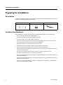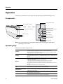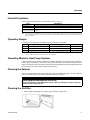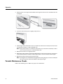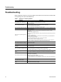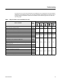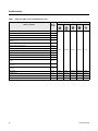
1
Installation, Operation,
and Maintenance
Variable Refrigerant Flow System
Convertible Ceiling/Floor Indoor Unit Series
Models: 4TVX0018B100NB, 4TVX0024B100NB
SAFETY WARNING
Only qualified personnel should install and service the equipment. The installation, starting up, and
servicing of heating, ventilating, and air-conditioning equipment can be hazardous and requires specific
knowledge and training. Improperly installed, adjusted or altered equipment by an unqualified person could
result in death or serious injury. When working on the equipment, observe all precautions in the literature
and on the tags, stickers, and labels that are attached to the equipment.
February 2013
VRF-SVX29A-EN
Introduction
Read this manual thoroughly before operating or servicing
this unit.
Warnings, Cautions, and Notices
Safety advisories appear throughout this manual as
required. Your personal safety and the proper operation of
this machine depend upon the strict observance of these
precautions.
The three types of advisories are defined as follows:
Indicates a potentially hazardous
situation which, if not avoided, could
result in death or serious injury.
Indicates a potentially hazardous
CAUTIONs situation which, if not avoided, could
result in minor or moderate injury. It
could also be used to alert against
unsafe practices.
Indicates
a situation that could result in
NOTICE
equipment or property-damage only.
WARNING
Important Environmental Concerns
Scientific research has shown that certain man-made
chemicals can affect the earth’s naturally occurring
stratospheric ozone layer when released to the
atmosphere. In particular, several of the identified
chemicals that may affect the ozone layer are refrigerants
that contain Chlorine, Fluorine and Carbon (CFCs) and
those containing Hydrogen, Chlorine, Fluorine and Carbon
(HCFCs). Not all refrigerants containing these compounds
have the same potential impact to the environment. Trane
advocates the responsible handling of all refrigerantsincluding industry replacements for CFCs such as HCFCs
and HFCs.
Important Responsible Refrigerant Practices
Trane believes that responsible refrigerant practices are
important to the environment, our customers, and the air
conditioning industry. All technicians who handle
refrigerants must be certified. The Federal Clean Air Act
(Section 608) sets forth the requirements for handling,
reclaiming, recovering and recycling of certain refrigerants
and the equipment that is used in these service procedures.
In addition, some states or municipalities may have
additional requirements that must also be adhered to for
responsible management of refrigerants. Know the
applicable laws and follow them.
WARNING
Proper Field Wiring and Grounding
Required!
Failure to follow code could result in death or serious
injury. All field wiring MUST be performed by qualified
personnel. Improperly installed and grounded field
wiring poses FIRE and ELECTROCUTION hazards. To
avoid these hazards, you MUST follow requirements for
field wiring installation and grounding as described in
NEC and your local/state electrical codes.
WARNING
Personal Protective Equipment (PPE)
Required!
Failure to wear proper PPE for the job being undertaken
could result in death or serious injury. Technicians, in
order to protect themselves from potential electrical,
mechanical, and chemical hazards, MUST follow
precautions in this manual and on the tags, stickers,
and labels, as well as the instructions below:
•
Before installing/servicing this unit, technicians
MUST put on all PPE recommended for the work
being undertaken. ALWAYS refer to appropriate
MSDS sheets and OSHA guidelines for proper PPE.
•
When working with or around hazardous chemicals,
ALWAYS refer to the appropriate MSDS sheets and
OSHA guidelines for information on allowable
personal exposure levels, proper respiratory
protection, and handling recommendations.
•
If there is a risk of arc or flash, technicians MUST put
on all PPE in accordance with NFPA 70E or other
country-specific requirements for arc flash
protection, PRIOR to servicing the unit.
Copyright
This document and the information in it are the property of
Trane and may not be used or reproduced in whole or in
part, without the written permission of Trane. Trane
reserves the right to revise this publication at any time and
to make changes to its content without obligation to notify
any person of such revision or change.
Trademarks
All trademarks referenced in this document are the
trademarks of their respective owners.
© 2013 Trane All rights reserved
VRF-SVX29A-EN
Table of Contents
Introduction . . . . . . . . . . . . . . . . . . . . . . . . . . . . . . . . . . . . . . . . . . . . . . . . . . . . . . . . . . . . 2
Warnings, Cautions, and Notices . . . . . . . . . . . . . . . . . . . . . . . . . . . . . . . . . . . . . 2
Important Environmental Concerns . . . . . . . . . . . . . . . . . . . . . . . . . . . . . . . 2
Important Responsible Refrigerant Practices . . . . . . . . . . . . . . . . . . . . . . . 2
Model Number Description . . . . . . . . . . . . . . . . . . . . . . . . . . . . . . . . . . . . . . . . . . . . . . 5
Preparing for Installation . . . . . . . . . . . . . . . . . . . . . . . . . . . . . . . . . . . . . . . . . . . . . . . . 6
Accessories . . . . . . . . . . . . . . . . . . . . . . . . . . . . . . . . . . . . . . . . . . . . . . . . . . . . . . . 6
Location Considerations . . . . . . . . . . . . . . . . . . . . . . . . . . . . . . . . . . . . . . . . . . . . 6
Unit Dimensions . . . . . . . . . . . . . . . . . . . . . . . . . . . . . . . . . . . . . . . . . . . . . . . . . . . 7
Service Clearances . . . . . . . . . . . . . . . . . . . . . . . . . . . . . . . . . . . . . . . . . . . . . . . . . 8
Installation . . . . . . . . . . . . . . . . . . . . . . . . . . . . . . . . . . . . . . . . . . . . . . . . . . . . . . . . . . . . . 9
Mounting the Unit . . . . . . . . . . . . . . . . . . . . . . . . . . . . . . . . . . . . . . . . . . . . . . . . . 9
Purging the Unit . . . . . . . . . . . . . . . . . . . . . . . . . . . . . . . . . . . . . . . . . . . . . . . . . . 10
Installing Refrigerant Piping . . . . . . . . . . . . . . . . . . . . . . . . . . . . . . . . . . . . . . . . 11
Leak Testing Pipe Connections . . . . . . . . . . . . . . . . . . . . . . . . . . . . . . . . . . . . . 13
Installing the Drain System . . . . . . . . . . . . . . . . . . . . . . . . . . . . . . . . . . . . . . . . . 15
Testing the Drainage . . . . . . . . . . . . . . . . . . . . . . . . . . . . . . . . . . . . . . . . . . 15
Insulation . . . . . . . . . . . . . . . . . . . . . . . . . . . . . . . . . . . . . . . . . . . . . . . . . . . . . . . . . . . . . 16
Refrigerant Pipes . . . . . . . . . . . . . . . . . . . . . . . . . . . . . . . . . . . . . . . . . . . . . . . . . 16
Drainage Hose . . . . . . . . . . . . . . . . . . . . . . . . . . . . . . . . . . . . . . . . . . . . . . . 16
Wiring the Unit . . . . . . . . . . . . . . . . . . . . . . . . . . . . . . . . . . . . . . . . . . . . . . . . . . . . . . . . 17
Power . . . . . . . . . . . . . . . . . . . . . . . . . . . . . . . . . . . . . . . . . . . . . . . . . . . . . . 17
Communication . . . . . . . . . . . . . . . . . . . . . . . . . . . . . . . . . . . . . . . . . . . . . . 17
Electronic Expansion Valve (EEV) Kit . . . . . . . . . . . . . . . . . . . . . . . . . . . . . 17
Configuration . . . . . . . . . . . . . . . . . . . . . . . . . . . . . . . . . . . . . . . . . . . . . . . . . . . . . . . . . 19
Using the VRF Wireless Remote Control . . . . . . . . . . . . . . . . . . . . . . . . . . . . . 19
The 2-Digit Segments . . . . . . . . . . . . . . . . . . . . . . . . . . . . . . . . . . . . . . . . .
Configuration Modes . . . . . . . . . . . . . . . . . . . . . . . . . . . . . . . . . . . . . . . . .
Mode 2: Option Setting . . . . . . . . . . . . . . . . . . . . . . . . . . . . . . . . . . . . . . . .
Mode 5: Option Setting . . . . . . . . . . . . . . . . . . . . . . . . . . . . . . . . . . . . . . . .
Mode A: Addressing . . . . . . . . . . . . . . . . . . . . . . . . . . . . . . . . . . . . . . . . . .
Mode d: Specific Digit Changing . . . . . . . . . . . . . . . . . . . . . . . . . . . . . . . .
21
21
22
24
26
27
Operation . . . . . . . . . . . . . . . . . . . . . . . . . . . . . . . . . . . . . . . . . . . . . . . . . . . . . . . . . . . . . 30
Components . . . . . . . . . . . . . . . . . . . . . . . . . . . . . . . . . . . . . . . . . . . . . . . . . . . . . 30
Operating Tips . . . . . . . . . . . . . . . . . . . . . . . . . . . . . . . . . . . . . . . . . . . . . . . . . . . . 30
Internal Protections . . . . . . . . . . . . . . . . . . . . . . . . . . . . . . . . . . . . . . . . . . . . . . . 31
Operating Ranges . . . . . . . . . . . . . . . . . . . . . . . . . . . . . . . . . . . . . . . . . . . . . . . . . 31
VRF-SVX29A-EN
3
Operating Mode for Heat Pump Systems . . . . . . . . . . . . . . . . . . . . . . . . . . . . . 31
Cleaning the Exterior . . . . . . . . . . . . . . . . . . . . . . . . . . . . . . . . . . . . . . . . . . . . . . 31
Cleaning the Air Filter . . . . . . . . . . . . . . . . . . . . . . . . . . . . . . . . . . . . . . . . . . . . . 31
Periodic Maintenance Checks . . . . . . . . . . . . . . . . . . . . . . . . . . . . . . . . . . . . . . . 32
Troubleshooting . . . . . . . . . . . . . . . . . . . . . . . . . . . . . . . . . . . . . . . . . . . . . . . . . . . . . . . 34
Warranty For Trane Advantage™ VRF Systems and Related Accessories . . . 37
Basic Warranty . . . . . . . . . . . . . . . . . . . . . . . . . . . . . . . . . . . . . . . . . . . . . . . . . . . 37
Exclusions and Limitations . . . . . . . . . . . . . . . . . . . . . . . . . . . . . . . . . . . . . . . . . 37
4
VRF-SVX29A-EN
Model Number Description
Model Number Description
4
T
V
D
0
0
1
8
A
1
0
0
N
A
1
2
3
4
5
6
7
8
9
10
11
12
13
14
Digit 1: Refrigerant
4 = R410A
Digit 2: Brand name
T = Trane
Digit 3: System type
V = Variable Refrigerant Flow
Digit 4: Configuration Type (also see separate tab)
B = mini 4-way cassette
C = 4-way cassette
D = MSP duct type (mid-pressure)
E = 1-way cassette
L = Slim duct type (low pressure)
A = HSP duct type high pressure)
X = Ceiling
W = High-wall
Digit 5: Reserved for future use
0 = Not currently used
Digit 6, 7, 8: Nominal capacity (Btu/h x 1,000)
007 = 7,000 Btu/h
020 = 20,000 Btu/h
024 = 24,000 Btu/h
009 = 9,000 Btu/h
030 = 30,000 Btu/h
012 = 12,000 Btu/h
018 = 18,000 Btu/h
048 = 48,000 Btu/h
006 = 6,000 Btu/h
036 = 36,000 Btu/h
060
068
076
096
=
=
=
=
60,000
68,000
76,000
96,000
Btu/h
Btu/h
Btu/h
Btu/h
Digit 9: Major development sequence
B = Second development sequence
Digit 10: Electric power supply characteristics
1 = 220/60/1
B = 220–240/50/1
Digit 11: Reserved for future use
0 = Not currently used
Digit 12: Controller
0 = None
R = Remote control standard
W = Wired control standard
Digit 13: Region of sale
N = North America (UL or ETL)
Digit 14: Minor design sequence
A = First design sequence
B = Second design sequence
VRF-SVX29A-EN
5
Preparing for Installation
Preparing for Installation
Accessories
In addition to product literature, the following accessories are supplied with this unit. The type and
quantity may differ, depending on the model.
Template
Plate hanger
Cable tie
Location Considerations
When deciding on a location for the indoor unit, the following factors must be considered:
6
•
The air inlet and outlet must be unobstructed.
•
The wall or ceiling must support the weight of the unit.
•
The wall or ceiling must not be subject to vibration.
•
Pre-plan for easy and short routing of the refrigerant tubing and wiring to the outdoor unit.
•
The air must circulate freely in the area to be cooled/heated.
•
Sufficient clearance must be maintained around the unit.
•
Condensate must be managed correctly and safety away from the unit.
•
The unit should be installed in a way that prevents unauthorized access.
•
The unit must not be installed in an area that is damp or could come into contact with water
(such as a laundry room).
•
The unit must not be exposed to direct sunshine or to other direct heat sources.
•
The filter must be able to be removed and cleaned easily.
•
The unit should be placed as far as possible from fluorescent lights so the remote control is not
subject to interference.
•
Care should be taken to prevent harmonics generated by loose or unsupported material in close
proximity to a running unit.
•
The unit must not be installed in an area that is exposed to salt, machine oil, sulfide gas, or
corrosive environmental conditions.
VRF-SVX29A-EN
Preparing for Installation
Unit Dimensions
Unit: inch (mm)
39.37 (1000)
25.59 (650)
7.76
(197)
9.45 (240)
36.3 (922)
1.77 (45)
7.87 (200)
1.97 (50)
Pipe outlet (bottom)
Air intake hole: 1.97 (50)
Wiring hole 1.09 (27.8)
1.73
(44)
Drain hose outlet
C
1.97 (50)
B A
No.
Name
A
Liquid pipe connection
1/4 (6.35)
B
Gas pipe connection
4TVX0018B100NB: 1/2 (12.70)
4TVX0024B100NB: 5/8 (15.88)
C
Drain pipe connection
Hose ID: 0.709 (18)
VRF-SVX29A-EN
Description
7
Preparing for Installation
Service Clearances
Ceiling installation
11.81 in.
(300 mm)
1.97 in.
(50 mm)
Floor installation
11.81 in.
(300 mm)
11.81 in.
(300 mm)
8
VRF-SVX29A-EN
Installation
Installation
Review “Installation Considerations” before proceeding with installation.
Follow the procedures in these sections in the order given.
Notes:
• Install the Y-joint before installing the indoor unit.
• Install an electronic expansion valve (EEV) on this unit. Refer to the EEV Kit installation
guide (VRF-SVN43) for information.
Mounting the Unit
Ceiling Installation
Note: If the ceiling is already constructed, piping must be laid into position before placing the unit
inside the ceiling.
CAUTION
Avoid equipment damage and personal injury!
Ensure that the ceiling is strong enough to support the weight of the indoor unit. Before
hanging the unit, test the strength of each of the attached suspension bolts.
1. Select the direction for the pipe connection. See figure.
2. Use the template to locate the position for the holes for the refrigerant pipes, drain hose, and
wiring.
• Drill 3-1/8 in. (100 mm) holes for refrigerant pipes and wiring.
• Drill 1-3/4 in. (40 mm) hole for drain hose. Holes should slant slight downward to ensure
smooth water flow.
3. Install anchor bolts.
4. Install unit onto the ceiling.
• Tilt the unit 2° lower on the side that will have the drain hose attached to it.
2
• If installing on a dropped ceiling, install a threaded rod with an anchor bolt or an expansion
bolt to suspend the unit below the ceiling.
VRF-SVX29A-EN
9
Installation
Floor Installation
1. Select the direction for the pipe connection.
2. Use the template to locate the position for the holes for the refrigerant pipes, drain hose, and
cables.
• Drill 3-1/8 in. (100 mm) holes for refrigerant pipes and cables.
• Drill 1-3/4 in. (40 mm) hole for drain hose. Holes should slant slight downward to ensure
smooth water flow.
3. Install the wall hanging plate.
4. Install the unit on the hanging plate, tilting it slightly to the side that will have the drain hose
attached to it.
5.
Purging the Unit
The unit is shipped from the factory with a holding charge of nitrogen. All of this gas must be
purged from the unit.
To purge the unit, remove the caps from the ends of both gas and liquid refrigerant pipes. Make
sure all gas has escaped before connecting the piping.
Note: To prevent dirt or foreign objects from getting into the pipes during installation, do not
remove the caps completely until you are ready to connect the piping.
10
VRF-SVX29A-EN
Installation
Installing Refrigerant Piping
Connect field-supplied piping using flared connections (not supplied) or by brazing. The large unit
port is for gas refrigerant; the small one is for liquid refrigerant.
Liquid refrigerant port
Gas refrigerant port
Cut or extend field-supplied piping as needed. Use the following procedures.
NOTICE
System Failure!
If brazing is used for pipe connections, a nitrogen purge is required to prevent the formation of
copper oxides inside the piping. Failure to follow this procedure could damage the system.
•
Before connecting the pipes, make sure they are free of dirt and debris.
•
Use insulated, unwelded, degreased, and deoxidized copper pipe (Cu-DHP type according to
ISO 1337 or UNI EN 12735-1) suitable for an operating pressure of at least 609.15 psi (4200 kPa)
and a burst pressure of at least 3002.28 psi (20,700 kPa). Copper pipe for hydro-sanitary
applications is unsuitable.
•
For sizing and limits (height difference, line length, maximum bends, refrigerant charge, and
so on) see the outdoor unit installation manual.
•
All refrigerant connections must be accessible for servicing and maintenance.
Pipe Cutting
Required tools:
• Pipe cutter
• Reamer
• Pipe holder
1. Using a pipe cutter, cut the pipe so that the cut edge is at 90° to the side of the pipe.
2. Use a reamer to remove all burrs at the cut edge.
See examples of correctly and incorrectly cut pipes.
Correct: 90º
Oblique
Rough
Burr
Flared Pipe Connections
Clutch type and wing nut type flare tools are available for flared pipe connections.
1. Slide the flare nut over the pipe to be flared.
VRF-SVX29A-EN
11
Installation
2. Slide the end of the pipe into the hole on the flaring bar that fits the pipe, leaving a length of
pipe, determined by tool type (see table), extending above the flaring bar. Clamp it down.
Length of pipe extending above flare bar
Flaring
bar
Pipe
Conventional flare tool
R-410A clutch type
0–0.020 in.
Clutch type
Wing nut type
0.04–0.06 in.
0.06–0.08 in.
3. Attach the yoke to the flaring bar, centering the conical part over the end of the pipe that is
extending above the flaring bar.
4. Tighten the yoke securely to flare the end of the pipe.
Yoke
Flaring bar
Copper pipe
Flare nut
5. Remove the pipe. The end of the pipe that you flared should look like the end of a trumpet. See
examples of correctly and incorrectly flared pipes.
Correct
12
Inclined
Damaged
surface
Cracked
Uneven
thickness
VRF-SVX29A-EN
Installation
6. Align the pipes and tighten the flare nuts manually and then with a spanner torque wrench,
applying the torque according to pipe dimensions:
Flare
dimension
(in.)
1/4 (6.35)
10.3–13.3 ft·lb
0.34–0.36
3/8 (9.52)
25.1–31.0 ft·lb
0.50–0.52
1/2 (12.70)
36.1–45.0 ft·lb
0.64–0.65
5/8 (15.88)
50.2–60.5 ft·lb
0.76–0.78
Flare shape (in.)
45°±2°
Connection
torque (ft·lb)
90°±2°
Outer diameter
(in. [mm])
R.016–.031
Leak Testing Pipe Connections
WARNING
Confined Space Hazards!
Do not work in confined spaces where refrigerant or other hazardous, toxic or flammable gas
may be leaking. Refrigerant or other gases could displace available oxygen to breathe, causing
possible asphyxiation or other serious health risks. Some gases may be flammable and or
explosive. If a leak in such spaces is detected, evacuate the area immediately and contact the
proper rescue or response authority. Failure to take appropriate precautions or to react properly
to such potential hazards could result in death or serious injury.
WARNING
Explosion Hazard!
Never use an open flame to detect gas leaks. It could result in an explosion. Use a leak test
solution for leak testing. Failure to follow recommended safe leak test procedures could result
in death or serious injury or equipment or property-only-damage.
Use only dry nitrogen with a pressure regulator for pressurizing unit. Do not use acetylene,
oxygen or compressed air or mixtures containing them for pressure testing. Do not use
mixtures of a hydrogen containing refrigerant and air above atmospheric pressure for pressure
testing as they may become flammable and could result in an explosion. Refrigerant, when
used as a trace gas should only be mixed with dry nitrogen for pressurizing units. Failure to
follow these recommendations could result in death or serious injury or equipment or
property-only damage.
Do not exceed unit nameplate design pressures when leak testing system. Failure to follow
these instructions could result in an explosion causing death or serious injury.
Notes:
• All required piping pressure tests must be completed in accordance with national and/or
local codes.
• When leak-testing refrigerant systems, observe all safety precautions.
• Leak test only one circuit at a time to minimize system exposure to potentially harmful
moisture in the air.
• Use R-410A refrigerant gas as a tracer for leak detection and use oil-pumped dry nitrogen
to develop required test pressures.
1. Close liquid line angle valve.
2. Connect R-410A refrigerant cylinder to high side charging port (at condenser or field supplied
discharge line access port). Add refrigerant to reach pressure of 12 to 15 psig.
VRF-SVX29A-EN
13
Installation
3. Disconnect refrigerant cylinder. Connect dry nitrogen cylinder to high side charging port and
increase pressure to 150 psig. Do not exceed high side (discharge) unit nameplate design
pressure. Do not subject low side (suction) components to high side pressure.
4. Check all piping joints, valves, etc. for leaks. Recommend using electronic detector capable of
measuring 0.1 oz/year leak rate.
5. If a leak is located, use proper procedures to remove the refrigerant/nitrogen mixture, break
connections and make repairs. Retest for leaks.
6. Make sure all service valves are open.
14
VRF-SVX29A-EN
Installation
Installing the Drain System
Follow these precautions and recommendations when installing the drain hose to the indoor unit:
•
The hose must have a downward slope.
•
The end of the hose must not be in standing water or in a hollow spot that can collect water.
•
Maintain a clearance of at least 2 in. (5 cm) between the end of the hose and the ground.
At least 2 in. (5 cm) between end
of hose and ground
•
An extension can be added to the drain hose if necessary. See figure below.
Testing the Drainage
After completing the installation, test the drainage to make sure there are no leaks:
1. Operate the unit in cool mode.
2. Remove drain pump cover.
3. Squirt water into the drain pan (see figure).
4. Confirm that the water flows out through the drain hose and that no leakage occurs at any of
the connections.
5. Reassemble the drain pump cover.
VRF-SVX29A-EN
15
Insulation
After determining that there are no leaks in the refrigerant pipes or drainage hose, insulate them
as described in these sections.
Refrigerant Pipes
1. Use the table below to select the insulation type for each pipe size.
Insulation Type
Pipe size
(in. [mm])
Pipe
Liquid pipe
Gas pipe(b)
1/4 (6.35) – 3/8 (9.52)
High humidity conditions(a)
(86°F [30°C], over 85%)
Standard conditions
(86°F [30°C], 85%)
EPDM or NBR
3/8 (9)
3/8 (9)
1/2 (12.70) – 2 (50.80)
1/2 (13)
1/2 (13)
1/4 (6.35)
1/2 (13)
3/4 (19)
3/8 (9.52) – 1 (25.40)
1-1/8 (28.58) – 1-3/4 (44.45)
2 (50.80)
3/4 (19)
1.0 (25)
1.0 (25)
1-1/4 (32)
1-1/2 (38)
(a) When installing insulation in any of the following environments, use insulation required for high humidity conditions: Buildings with close proximity to
bodies of water or hot springs or on the side of a hill in which the building is partly covered by earth; ceilings frequently exposed to moisture such as
in restaurants, saunas, swimming pools, and corridors of dormitories or studios near a frequently-used outdoor exit; buildings with no ventilation system.
(b) Internal temperature of gas pipe is higher than 248°F (120°C).
2. Wrap insulation around the entire surface of each pipe, from the indoor unit to the outdoor unit,
overlapping insulation to avoid gaps. Clamp insulation tightly to pipe.
• Do not wrap the gas and liquid refrigerant pipes together.
• Avoid compressing the insulation as much as possible.
• Be sure there are no cracks or deformities in the insulation at bends in pipes.
• If necessary double the insulation to prevent condensation from forming in warm or humid
areas.
• Cut off excess insulation.
Drainage Hose
Insulate (field supplied) the entire surface of the drain pipe that is inside the building, including the
connection between the drain hose and drain stub. Clamp tightly.
16
VRF-SVX29A-EN
Wiring the Unit
Wiring the Unit
Observe the following precautions when making electrical connections.
WARNING
Hazardous Voltage!
Disconnect all electric power, including remote disconnects before servicing. Follow proper
lockout/tagout procedures to ensure the power can not be inadvertently energized. Failure to
disconnect power before servicing could result in death or serious injury.
NOTICE
Use Copper Conductors Only!
Unit terminals are not designed to accept other types of conductors. Failure to use copper
conductors could result in equipment damage.
•
•
•
•
•
•
•
•
•
•
•
•
•
•
•
Make all electrical connections in accordance with electrical codes and ordinances.
Select the power cable in accordance with relevant local and national regulations.
Wire size must comply with local and national code.
Use grade H07RN-F or H05RN-F power cable.
Connect the power cable into the power cable terminal and fasten it with a clamp.
Unbalanced power must be maintained within 10% of supply rating among whole indoor units.
Significantly unbalanced power may shorten the life of the system. If the unbalanced power is
greater than 10% of supply rating, the unit will stop and an error code will be generated.
Connect the power cable to the auxiliary circuit breaker. An all-pole disconnection from the
power supply must be incorporated in the fixed wiring (1/8 in. [3 mm]).
All wiring must be protected from weather and damage.
Maintain a distance of 2 in. (50 mm) or more between power and communication cables to
prevent interference.
Maintain a voltage drop of less than 10% between the power source and the unit(s).
Use an appropriate screwdriver for tightening the terminal screws. A screwdriver with a small
head will strip the head and make proper tightening impossible.
Over-tightening the terminal screws may break them.
Tightening torque for M4 screws: 0.86–1.06 lbf·ft (12.0–14.7 kgf·cm).
After making a knockout hole, apply rust-preventive paint to the bare metal around the hole.
Secure the cable conduit to the outdoor knockout using the proper connector and bushing.
Power
Connect the power cable to terminals 1(L) and 2(N) on each indoor unit. Refer to wiring diagram.
Communication
If installing a wired remote control, connect the communication cable to terminals F3 and F4. Refer
to Figure 1.
Electronic Expansion Valve (EEV) Kit
EEV kits are required for high-wall and convertible units. Refer to the Figure 1.
VRF-SVX29A-EN
17
Wiring the Unit
Figure 1.
Wiring diagram
Outdoor unit
F1 F2
Wired remote
control
F3 F4
208–230 V
1(L) 2(N)
F1 F2
Indoor unit 1
1(L) 2(N)
F1
F2
Indoor unit 2
1(L) 2(N)
F1
F2
F3
F4
F2
F1
F1 F2 F1
1(L) 2(N)
F1 F2
Indoor unit 4
18
L
N
Indoor unit 3
F2 F1 F2
1(L) 2(N)
F1 F2
Indoor unit 5
EEV kit
N
L
N
1(L) 2(N)
L
N
L
F1 F2
Indoor unit 6
VRF-SVX29A-EN
Configuration
Configuration
All VRF indoor units are factory configured. If modifications are required, one of the following
control devices can be used:
•
VRF Wireless Remote Control (instructions follow)
•
VRF Wired Remote Control
•
VRF Enterprise Management Software
•
VRF Auto-Commissioning Tool
•
VRF System Controller
Note: Indoor unit options are configured at the factory; changes are not required for typical
installations.
Using the VRF Wireless Remote Control
To change configurations of the VRF system using the VRF Wireless Remote Control, follow this
procedure:
1. Remove the batteries from the remote control, and re-insert them while pressing the Temp+ and
Temp- buttons simultaneously (refer to Figure 3).
The first 2-digit segment of a 24-digit sequence will appear on the wireless remote control
display, as shown:
2. To advance to the next 2-digit segment, press the Mode button (Figure 3). Continue pressing
the Mode button until the two-digit segment appears that corresponds to the option setting or
address setting you want to view or change.
Each 2-digit segment is differentiated from the others by a combination of operation mode
(Auto/Cool/Dry...) and ON/OFF icons, as shown below. (See “The 2-Digit Segments,” for more
detailed information.)
Digits 2 and 3
Digits 4 and 5
Digits 6 and 8
...and so on,
through digits 23
and 24.
Note: Digits 1, 7, 13, and 19 do not appear and are not used for configuration.
3. To change the value of the left digit on the display, press the Fan down button.
To change the value of the right digit on the display, press the Fan up button.
Note: Values and their corresponding settings are listed in the following pages of this section
of the manual.
4. To save the setting, press the Power button twice.
5. To restore the wireless remote control to normal operating mode, remove the batteries from
the remote control. Then re-insert them.
VRF-SVX29A-EN
19
Configuration
Figure 2. VRF Wireless Remote Control
2-digit segment
Power button
Mode button
Temp up
Temp down
20
Fan up
Fan down
VRF-SVX29A-EN
Configuration
The 2-Digit Segments
Each 2-digit segment is differentiated from the others by a combination of operation mode and
timer on/off icons. See Figure 4.
Figure 3. Two-digit segments in the 24-digit sequence
Notes:
• Digits 1, 7, 13, and 19 (shown in green) are factory set and cannot be changed. They do not
appear on the display.
• Digit 2 (shown in red) is used to change the configuration mode (see “Configuration
Modes” for details).
• The digit numbers shown in gray above each digit (D2, D3, etc.) do not appear on the
display.
Configuration Modes
Digit 2 (shown in red in Figure 4) is used to set the configuration mode. The four modes are shown
in Figure 5.
Figure 4. The four configuration modes
Mode “2”: Option setting
VRF-SVX29A-EN
Mode “5”: Option setting
Mode “A”: Addressing
Mode “d”: Specific digit changing
21
Configuration
Mode 2: Option Setting
When digit 2 is set to a value of “2,” the options shown in Table 1 can be set to the values in the
right column.
Table 1.
Option setting mode: Digit 2 = 2
Display
screen
(mode and
On/Off)
Digit
N/A
1
Factory set to 0
Cannot be changed. Not seen in configuration mode.
2
Option setting mode
2
3
Robot cleaning
0: Disabled
1: Enabled
4
Remote sensor
0: Disabled
1: Enabled
5
Central control
0: Disabled
1: Enabled
6
RPM up
0: Disabled
1: Enabled
7
Factory set to 1
Cannot be changed. Not seen in configuration mode.
8
Drain pump
0: Disabled
1: Enabled (no delay)
2: Enabled (3-min delay)(a)
9
Hot water heater
0: Disabled
1: Enabled
10
Electronic heater
0: Disabled
1: Enabled
11
EEV position when heating is
satisfied
0: EEV step is minimum (default)
1: Reduced noise setting
12
Master/Slave unit
designation(b)
0: Slave
1: Master
13
Factory set to 2
Cannot be changed. Not seen in configuration mode.
N/A
D11 D12
N/A
22
Option description
Set digit to...
VRF-SVX29A-EN
Configuration
Table 1.
Option setting mode: Digit 2 = 2
Display
screen
(mode and
On/Off)
N/A
Digit
Option description
Set digit to...
14
External control
0: Disabled
1: On/Off control
2: Off-only control
15
External control output
0: Thermostat control
1: User controlled input
16
S-plasma ion
0: Disabled
1: Enabled
17
Buzzer
0: Enabled
1: Disabled
18
Filter timer (hours of use)
2: 1000
6: 2000
19
Factory set to 3
Cannot be changed. Not seen in configuration mode.
20
Associating wireless remote
control with indoor unit(s)
0, 1: Channel 1
2: Channel 2
3: Channel 3
4: Channel 4
21
Heat setting compensation
0: Disabled
1: 3.6°F (2°C)
2: 9°F (5°C)
22
0: EEV step is minimum
EEV step of stopped unit
during oil return/defrost mode 1: Oil return or reduce noise in defrost mode
23
Motion detection sensor
0:
1:
2:
3:
4:
5:
6:
7:
8:
24
N/A
—
Disabled
Disabled
Disabled
Disabled
Disabled
Disabled
Disabled
Disabled
Disabled
in
in
in
in
in
in
in
in
30 minutes if no motion is detected
60 minutes if no motion is detected
120 minutes if no motion is detected
180 minutes if no motion is detected
30 minutes if no motion is detected and advanced function(c)
60 minutes if no motion is detected and advanced function
120 minutes if no motion is detected and advanced function
180 minutes if no motion is detected and advanced function
(a) Cassette-type indoor units are set to “Enabled (3-minute delay)” regardless of digit 8 setting.
(b) For heat pump systems, the master indoor unit controls whether the system operates in heating or cooling. If the master indoor unit calls for heating
and slave indoor units calls for cooling, the master indoor unit (and any other slave indoor units that call for heating) will operate in heating mode. The
slave indoor units that call for cooling will do nothing.
(c) Advanced function: Controls heating/cooling or power saving with motion detection.
VRF-SVX29A-EN
23
Configuration
Mode 5: Option Setting
When digit 2 is set to a value of “5,” the options shown in Table 2 can be changed to the values in
the right column.
Table 2.
Option setting mode: Digit 2 = 5
Display
screen
(mode and
On/Off)
Digit
Option description
1
Factory set to 0
Cannot be changed. Not seen in configuration mode.
2
Option setting mode
5
3
Auto-changeover (HR only)
0: Disabled
1: Enabled (see Figure 6)
Heating deadband
4
Note: Applies only when digit 3 is set to “1”
(auto-changeover mode is enabled).
Cooling deadband
5
Note: Applies only when digit 3 is set to “1”
(auto-changeover mode is enabled).
Standard for auto-changeover (heating to cooling)
6
Note: Applies only when digit 3 is set to “1”
(auto-changeover mode is enabled).
7
Factory set to 1
Standard for auto-changeover (cooling to heating)
8
24
Set digit to...
Note: Applies only when digit 3 is set to “1” (autochangeover mode is enabled).
0:
1:
2:
3:
4:
5:
6:
7:
Disabled
0.9°F (0.5°C)
1.8°F (1°C)
2.7°F (1.5°C)
3.6°F (2°C)
4.5°F (2.5°C)
5.4°F (3°C)
6.3°F (3.5°C)
0:
1:
2:
3:
4:
5:
6:
7:
Disabled
0.9°F (0.5°C)
1.8°F (1°C)
2.7°F (1.5°C)
3.6°F (2°C)
4.5°F (2.5°C)
5.4°F (3°C)
6.3°F (3.5°C)
0:
1:
2:
3:
4:
5:
6:
7:
1.8°F
2.7°F
3.6°F
4.5°F
5.4°F
6.3°F
7.2°F
8.1°F
(1°C)
(1.5°C)
(2°C)
(2.5°C)
(3°C)
(3.5°C)
(4°C)
(4.5°C)
Cannot be changed. Not seen in configuration mode.
0:
1:
2:
3:
4:
5:
6:
7:
1.8°F
2.7°F
3.6°F
4.5°F
5.4°F
6.3°F
7.2°F
8.1°F
(1°C)
(1.5°C)
(2°C)
(2.5°C)
(3°C)
(3.5°C)
(4°C)
(4.5°C)
VRF-SVX29A-EN
Configuration
Table 2.
Option setting mode: Digit 2 = 5
Display
screen
(mode and
On/Off)
Digit
Option description
Set digit to...
0:
1:
2:
3:
4:
5:
6:
7:
Time required for mode change
9
10
Note: Applies only when digit 3 is set to “1” (autochangeover mode is enabled).
Compensation option for height or pipe length difference
between indoor units
5 minutes
7 minutes
9 minutes
11 minutes
13 minutes
15 minutes
20 minutes
30 minutes
0: Use default value
1: Use when height or pipe length difference is as
specified in Note 1.
2: Use when height or pipe length difference is as
specified in Note 2.
Notes:
1. Height difference between the indoor unit being configured and the lowest indoor unit is > 98.4 ft (30 m), or
pipe length difference between the outdoor unit and the furthest indoor unit and the outdoor unit and the indoor unit being configured is > 360.9 ft
(110 m).
2. Height difference between the indoor unit being configured and the lowest indoor unit is 49.2–98.4 ft (15–30 m), or
pipe length difference between the outdoor unit and the furthest indoor unit and the outdoor unit and the indoor unit being configured is 164–
360.9 ft (50–110 m).
Example: If the unit being configured is 60 ft away from the outdoor unit, and the furthest in door unit is 300 ft from the outdoor unit, the pipe
length difference is 240 ft (300-60=240), so Digit 10 should be set to “2.”
Heating On
Heating Off
Cooling On
Cooling Off
Figure 5. Heat recovery unit operating in auto-changeover mode
Standard temp. for
Heating Cooling
Temp.
C
B
Standard temp.
for Cooling
Ts
Set temp.
for Auto mode
A
Standard temp.
for Heating
D
Standard temp.
for Cooling
Heating
A : Set with digit 4.
B : Set with digit 5.
C : Set with digit 6.
D : Set with digit 8.
Note: Minimum compressor off time for heating or cooling is set by digit 9.
VRF-SVX29A-EN
25
Configuration
Mode A: Addressing
When digit 2 is set to a value of “A,” unit address settings can be changed. See Figure 7, Figure 8,
and Table 3.
The indoor unit is factory-configured for auto-addressing mode. The factory default address is
0A0000-100000-200000-300000. If the default address is manually changed, the auto-addressing
mode is no longer active.
If the address has been manually changed, and the installer wants to restore auto-addressing
mode, all indoor units in the system must be returned to the initial factory default address.
Figure 6. Address setting mode (digit 2 = A): Digits 2–6
Figure 7.
26
Addressing mode for remote control, Digits 9–12
VRF-SVX29A-EN
Table 3.
Address setting mode: Digit 2 = A
Display
screen
(Mode and
On/Off)
Digit
Option
1
Factory set to 0
Set digit to...
Cannot be changed. Not seen in configuration mode.
2
Addressing mode
A
3
Unit/RMC address
0: Automatic address setting (default)
1: Manual address setting
4
Hundreds digit of address
Address
5
Tens digit of address
Address
6
Ones digit of address
Address
Mode d: Specific Digit Changing
When digit 2 is set to a value of “d,” a single, specific digit can be changed. See Figures 9–11 and
Table 4. This mode can be used as a shortcut when only a single digit needs to be changed.
Figure 8. Specific digit changing mode
The example in Figure 10 shows how to use this mode to change the external control option setting
from On/Off control to Off-only control. (For the details on this option, see Table 1.)
VRF-SVX29A-EN
27
Configuration
Figure 9. Example of using the specific digit changing mode to change an option setting
•
•
•
•
Digit 2 is set to “d” (the specific digit setting mode).
Digit 3 is set to “2” (the option setting mode; refer to “Mode 2: Option Setting”).
Digits 4 and 5 are set to “14” (the position of the digit for external control; refer to Table 1).
Digit 6 is changed from “1” (On/Off control) to “2” (Off-only control); refer to Table 1.
The example in Figure 11 shows how to use this mode to change a unit address from “137” to “134.”
Figure 10. Example of using the specific digit changing mode to change a unit address
•
•
•
•
28
Digit 2 is set to “d” (the specific digit setting mode).
Digit 3 is set to “A” (the addressing mode).
Digits 4 and 5 are set to “06” because the 6th digit (“7”) is the digit that is to be changed.
Digit 6 is changed from “1” (On/Off control) to “2” (Off-only control).
VRF-SVX29A-EN
Table 4.
Specific digit changing mode: Digit 2 = d
Display
screen (Mode
and On/Off)
Digit
Option
1
VRF-SVX29A-EN
Factory set to 0
Set digit to...
Cannot be changed. Not seen in configuration mode.
2
Specific digit changing mode
d
3
Configuration setting mode
4
Position of digit in 24-digit sequence: Tens digit
Value that represents position (such as “0” if it is the 9th
digit in the sequence)
5
Position of digit in 24-digit sequence: Ones digit
Value that represents position (such as “9” if it is the 9th
digit in sequence)
6
Setting value
The desired setting mode: 1, 2, 5, or A
(see Figure 5)
Appropriate value for operation, function, or address
29
Operation
Operation
Familiarize yourself with the unit components and operating tips before operating the unit.
Components
Remote control sensor
Air flow blade (up/down)
Air flow blade (left/right)
Defrosting indicator
(except cooling-only models)
Filter sign indicator
Fan indicator
Air filter (inside)
Timer indicator
Auto mode indicator
Grille
Operation indicator
Power button
Note: Your unit and display may look slightly different from the illustration shown above,
depending on your model.
Operating Tips
Follow these tips when using your unit:
30
Cooling
If the outside temperature is much higher than the selected indoor temperature, it
may take longer than expected to achieve the desired temperature.
Avoid making extreme changes in the temperature setting. This practice wastes
energy and does not cool the room faster.
Heating
Because the unit heats the room by removing heat energy from outdoor air, the
heating capacity may decrease when outdoor temperatures are extremely low. If the
unit provides insufficient heat, use an additional heating source in combination with
the unit.
Defrost
When the unit runs in Heat mode, frost may form due to the temperature difference
between the unit and the outside air. If this happens:
• The unit stops heating.
• The unit will operate automatically in Defrost mode for 10 minutes.
• The steam produced on the outdoor unit in Defrost mode is safe.
No intervention is required; after about 10 minutes, the unit will resume normal
operation.
The unit will not operate when it starts to defrost.
Fan
The fan may not operate for 3–5 minutes after turning on the unit, to prevents cold
air from blowing on occupants while the unit is warming up.
High indoor and outdoor
temperatures
If both indoor and outdoor temperatures are high and the unit is running in Heat
mode, the outdoor unit fan and compressor may stop at times. This is normal; wait
until the unit turns on again.
Power failure
A power failure will cause the unit to stop operating. When power returns, the unit
will automatically resume operation.
Minimum Off Timer
If the unit has just been turned on, it will not produce cool/warm air for 3 minutes.
This delay mechanism protects the outdoor unit compressor.
VRF-SVX29A-EN
Operation
Internal Protections
Internal protections operate if an internal fault occurs in the unit.
Type
Description
Cold air dump
The internal fan will be off to prevent a cold air dump when the heat pump is in defrost mode.
Defrost cycle
The internal fan will be off to prevent a cold air dump when the heat pump is in defrost mode.
Anti-short cycle timer
The compressor observes a 3-minute off time when cycling power to the unit or after an
outage.
Note: If the heat pump is operating in Heat mode, a defrost cycle is activated to remove frost from an outdoor unit that may
have accumulated at low temperatures. The internal fan is switched off automatically and restarted only after the defrost
cycle is completed.
Operating Ranges
For efficient use, operate the unit within the ranges shown in this table.
Mode
Cooling
Outdoor temperature
23°F (-5°C) to 118°F (48°C)
Indoor temperature
Indoor humidity
64°F (18°C) to 90°F (32°C)
80% or less
Heating
-4°F (-20°C) to 75°F (24°C)
81°F (27°C) or less
—
Drying
23°F (-5°C) to 118°F (48°C)
64°F (18°C) to 90°F (32°C)
—
Note: The standardized temperature for heating is 45˚F (7˚C). If the outdoor temperature drops to 32˚F (0˚C) or below, the
heating capacity can be reduced depending on the temperature condition. If the cooling operation is used at over 90˚F
(32˚C) (indoor temperature), it does not cool at its full capacity.
Operating Mode for Heat Pump Systems
For heat pump systems, the main indoor unit controls whether the system operates in heating or
cooling. If the main indoor unit calls for heating and sub-indoor units calls for cooling, the main
indoor unit (and any other sub-indoor units that call for heating) will operate in heating mode, and
the sub-indoor units that call for cooling will do nothing.
Cleaning the Exterior
Use a dry or damp cloth to wipe the surface of the unit as needed. If necessary, use mild soap and
water on a damp cloth. Use a soft brush to remove dirt from the grill.
NOTICE
Avoid equipment damage and risk of fire!
Avoid using benzene or other flammable solvents. They may damage the surface of the unit
and increase the potential for fire.
Cleaning the Air Filter
1. Open the grill by pressing the “PUSH” signs, located in three places.
VRF-SVX29A-EN
31
Operation
2. Hold the grill at a 45° angle. Push the bottom of the grill to make sure it is unhooked. Then lift
up the grill.
3. To remove the air filter, press it slightly and pull it out.
4. Clean the grill and air filter with a vacuum or soft brush. If the dust is too thick, rinse them under
running water and dry in a well-ventilated area.
Note: Drying the air filter in a confined or humid area may cause odors to develop. If odors
occur, re-clean and dry it in a well-ventilated area.
5. Replace the air filter in its original position.
6. After cleaning the air filter, press the Filter Reset button on the remote control for 2 seconds to
reset the filter schedule. The filter indicator lights when it is time the clean the filter again.
7.
Replace the grill by reversing the first three steps.
Note: If the angle on the air flow blades changed from opening the grill, turn the circuit breaker
off and on again to restore the blades to their proper angle.
Periodic Maintenance Checks
Refer to the schedule given in Table 5 for proper unit maintenance.
32
VRF-SVX29A-EN
Operation
Note: If the unit will not be used for an extended period of time, operate it in Fan mode for 3–4
hours to thoroughly dry it and then disconnect the power plug. Moisture left in the
components can cause odors and internal damage.
Table 5.
Maintenance schedule
Description
Clean the air filter(a)
Monthly
Every 4 months Once a year
Clean the condensate drain pan(b)
x
Thoroughly clean the heat exchanger(b)
Clean the condensate drain pipe(b)
Replace remote control batteries (a)
As needed
x
x
x
x
(a) The described operations should be performed more frequently if the area of installation is very dusty.
(b) These operations must always be performed by qualified personnel. For more detailed information, see the installation
manual for this unit.
VRF-SVX29A-EN
33
Troubleshooting
Troubleshooting
Refer to Table 6 for solutions to common problems and to Table 7 for a list of alarm conditions with
corresponding error codes and LED behavior.
Table 6.
Solutions to common problems
Problem
Solution
The unit does not operate
immediately after restarting it.
The anti-short cycle timer prevents the unit from operating immediately to keep
it from overloading. The unit will start in 3 minutes.
The unit does not operate.
Verify the following:
The power plug is properly inserted into the wall receptacle.
There has not been a power failure.
The circuit breaker is switched on/fuses are good.
The temperature does not change. Verify that the unit is not operating in Fan mode. If it is, select a different mode.
The unit is not producing warm/
cool air.
Verify the following:
Temperature setting on remote control is higher/lower than the current
temperature.
Air filter is not clogged with dirt.
If the unit has just been turned on, wait 3 minutes for the anti-short cycle timer
to expire.
Air flow is unobstructed.
Line size and length is correct and does not exceed factory recommendations.
Operating mode is heat/cool.
If unit is not producing warm air, is it set to Cool mode?
Remote control is not for a cooling-only unit.
That the unit has not been installed in direct sunlight. If so, hang curtains or
shades on windows to filter the sun and increase unit efficiency.
The fan speed does not change.
Verify that Auto or Dry mode is selected. Either of these modes automatically
adjust the fan speed.
Timer function does not work.
Press the Power button on the remote control after setting the time.
Odors permeate the room during
operation.
Verify the origin of the odor. Operate the unit in Fan mode or open the windows
to air out the room.
A bubbling sound may be heard:
The unit makes a bubbling sound When the refrigerant is circulating through the compressor.
By the drain pump inside the unit when you press the Power button.
Water is dripping from the air flow If the unit has been running for an extended period of time with the blades fully
blades.
open, adjust the blades to mid-position to alleviate condensation formation.
Verify that:
Batteries are not depleted.
Batteries are correctly installed.
The remote control is not working.
Nothing is blocking the remote control sensor.
No strong fluorescent or neon lighting is near the unit, which may interrupt the
signal.
The unit does not turn on/off with
Ensure that the wired remote control is not set for Group Control.
the wired remote control.
Indicators on the digital display
flash.
34
Press the Power button on the remote control to turn the unit off. Then switch the
circuit break off and then on again.
VRF-SVX29A-EN
Troubleshooting
If an error occurs, one of more of the LEDs on the display (see “Components” for their location)
will flicker. As a protection strategy, the unit stops operating (and the LED turns off). If the unit is
turned on before the problem is resolved, the LED will resume flickering and the unit will stop
operating again.
Table 7.
Diagnostic LEDs for the convertible indoor unit
LED display
Alarm condition
Indoor temperature sensor error (shorted or open)
Error
code
Power
Timer
Fan
Filter
Defrost
E121
Off
Flickering
Off
Off
Off
Flickering
Flickering
Off
Off
Off
Off
Off
Flickering
Off
Off
Flickering
Off
Flickering
Off
Off
Off
Flickering
Flickering
Off
Off
Off
Flickering
Flickering
Flickering
Off
Evap-in sensor error (shorted or open)
E122
Evap-out sensor error (shorted or open)
E123
Discharge sensor error (shorted or open)
E126
Indoor fan error
E154
Outdoor temperature sensor error (shorted or open)
E221
Condenser sensor error (shorted or open)
E237
Discharge sensor error
E251
No communication between indoor and outdoor units for 2 minutes
E101
Communication error received from outdoor unit
E102
3-minute tracking error on outdoor unit
E202
Communication error after tracking due to non-matching quantity of
installed indoor units
E201
Error due to repeated communication address
E108
Communication address not confirmed
E109
Error due to opened EEV (2nd detection)
E151
Error due to closed EEV (2nd detection)
E152
Evap-in sensor is loose
E128
Evap-out sensor is loose
E129
Thermal switch error (open)
E198
VRF-SVX29A-EN
35
Troubleshooting
Table 7.
Diagnostic LEDs for the convertible indoor unit
LED display
Alarm condition
Error
code
Condenser mid-sensor is loose
E241
Refrigerant leakage (2nd detection)
E554
Abnormally high temperature on condenser (2nd detection)
E450
Low pressure switch (2nd detection)
E451
Abnormally high discharge air temperature on outdoor unit (2nd
detection)
E416
Indoor unit operation stopped due to unconfirmed error on outdoor unit
E559
Reverse phase detection error
E425
Compressor operation stop due to freeze detection(6th detection)
E403
High pressure sensor is loose
E301
Low pressure sensor is loose
E306
Outdoor unit compression ratio error
E428
Outdoor sump down_1 prevention control
E413
Compressor operation stopped due to low pressure sensor prevention
control
E410
Simultaneous opening of cooling/heating MCU solenoid valve (1st
detection)
E180
Simultaneous opening of cooling/heating MCU solenoid valve (2nd
detection)
E181
Float switch
E153
Power
Timer
Fan
Filter
Defrost
Off
Flickering
Flickering
Flickering
Off
Off
Off
Flickering
Flickering
Off
EEPROM error
E162
Flickering
Flickering
Flickering
Flickering
Flickering
EEPROM option error
E163
Flickering
Flickering
Flickering
Flickering
Flickering
Incompatible indoor unit error
E164
Off
Off
Off
Flickering
Off
36
VRF-SVX29A-EN
Warranty For Trane Advantage™ VRF Systems and Related Accessories
Warranty For Trane Advantage™ VRF Systems and
Related Accessories
Products Covered. This warranty is extended by Trane, and applies to all Trane Advantage™ VRF
systems and accessories for these products which are sold by Trane and applied in accordance with
Trane specifications.
Basic Warranty
The warrantor warrants for a period of 12 months from the initial start-up or 18 months from date
of shipment, whichever is less, against failure due to defects in material and manufacture and that
it has the capacities and ratings set forth in Company’s catalogs and bulletins (“Warranty”).
If the following conditions are met, the warrantor extends this basic warranty period to five (5)
years from date of start-up:
• The system is designed using an approved application tool (VRF Select).
• The system is installed by a contractor who has successfully completed a Trane factory training
class.
• A verified commissioning report from the Trane VRF Commissioning Tool is submitted.
Exclusions and Limitations
Exclusions from this Warranty include damage or failure arising from: wear and tear; corrosion,
erosion, deterioration; modifications made by others to the Equipment; repairs or alterations by
a party other than Company that adversely affects the stability or reliability of the Equipment;
vandalism; neglect; accident; adverse weather or environmental conditions; abuse or improper
use; improper installation; commissioning by a party other than Company; unusual physical or
electrical or mechanical stress; operation with any accessory, equipment or part not specifically
approved by Company; refrigerant not supplied by Company; and/or lack of proper maintenance
as recommended by Company. Company shall not be obligated to pay for the cost of lost
refrigerant or lost product. Company's obligations and liabilities under this Warranty are limited to
furnishing replacement equipment or parts, at its option, FCA (Incoterms 2000) factory or
warehouse (f.o.b. factory or warehouse for US domestic purposes) at Company-designated
shipping point, freight-allowed to Company's warranty agent's stock location, for all nonconforming Company-manufactured Equipment (which have been returned by Customer to
Company. Returns must have prior written approval by Company and are subject to restocking
charge where applicable. Equipment, material and/or parts that are not manufactured by Company
are not warranted by Company and have such warranties as may be extended by the respective
manufacturer. COMPANY MAKES NO REPRESENTATION OR WARRANTY, EXPRESS OR IMPLIED,
REGARDING PREVENTION OF MOLD/MOULD, FUNGUS, BACTERIA, MICROBIAL GROWTH, OR
ANY OTHER CONTAMINATES. No warranty liability whatsoever shall attach to Company until
Customer’s complete order has been paid for in full and Company's liability under this Warranty
shall be limited to the purchase price of the Equipment shown to be defective. EXCEPT FOR
COMPANY’S WARRANTY EXPRESSLY SET FORTH HEREIN, COMPANY DOES NOT MAKE, AND
HEREBY EXPRESSLY DISCLAIMS, ANY WARRANTIES, EXPRESS OR IMPLIED CONCERNING ITS
PRODUCTS, EQUIPMENT OR SERVICES, INCLUDING, WITHOUT LIMITATION, ANY WARRANTY
OF DESIGN, MERCHANTABILITY OR OF FITNESS FOR A PARTICULAR PURPOSE, OR OTHERS
THAT ARE ALLEGED TO ARISE FROM COURSE OF DEALING OR TRADE.
Additional warranty protection is available on an extra-cost basis and must be in writing and
agreed to by an authorized signatory of the Company. Additional terms and conditions of warranty
coverage are applicable for refrigeration equipment. If you wish further help or information
concerning this warranty, contact: Trane—Warrantor, 2701 Wilma Rudolph Blvd., Clarksville, TN
37040.
VRF-SVX29A-EN
37
38
VRF-SVX29A-EN
VRF-SVX29A-EN
39
The manufacturer optimizes the performance of homes and buildings around the world. A business of Ingersoll
Rand, the leader in creating and sustaining safe, comfortable and energy efficient environments, the manufacturer
offers a broad portfolio of advanced controls and HVAC systems, comprehensive building services, and parts. For
more information, visit www.IRCO.com.
The manufacturer has a policy of continuous product and product data improvement and reserves the right to change design and specifications without notice.
© 2013 Trane All rights reserved
VRF-SVX29A-EN
New
01 Feb 2013
We are committed to using environmentally
conscious print practices that reduce waste.