1
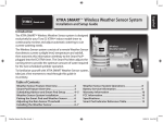
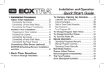
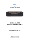
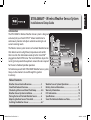
Español
XTRA SMART TM Wireless Weather Sensor System
Installation and Setup Guide
Introduction
The XTRA SMARTTM Wireless Weather Sensor system is designed
exclusively for your Toro EC.XTRATM indoor model timer to
continuously monitor and adjust automatic watering to suit
current watering needs.
The Wireless Sensor system consists of a remote Weather Sensor
that detects current sunlight level, temperature and rainfall,
then transmits this information wirelessly to the Smart PodTM
plugged into the EC·XTRA timer. The Smart Pod then adjusts the
running time to provide the optimum amount of water required
for the next scheduled sprinkler operation.
To familiarize yourself with XTRA SMART Weather Sensor system,
take just a few moments to read through this guide in
its entirety.
Wireless
Weather Sensor
Smart Pod
TM
Table of Contents
Weather Sensor Feature Overview............................... 2
Smart Pod Feature Overview.......................................... 3
Scheduling Advisor and Smart Pod Setup................ 4–5
Weather Sensor System Installation............................ 6
Pairing the Smart Pod and Weather Sensor............. 6
Adjusting the Rain Sensor Threshold.......................... 6
Installing the Weather Sensor........................................ 6–7
Weather Sensor Doc Rev A.indd 1
Weather Sensor System Operations.............................. 8
Battery Service Information.............................................. 9
Warranty Information.......................................................... 10
FCC Information..................................................................... 10
Specifications.......................................................................... 11
Smart Pod Indicator Reference Table............................ 12
12/23/10 3:44 PM
Weather Sensor Feature Overview
1. Rain Sensor Test Pin
Pressing the test pin simulates operation of
the Rain Sensor by transmitting a signal to
the Smart Pod.
1
3
2
4
5
2. Rain Sensor Adjustment Cap
The Rain Sensor sensitivity is adjustable to
suspend watering at 1/8”, 1/4”,, 1/2” and 3/4”
(3 mm, 6 mm, 12 mm and 19 mm) of
accumulated rainfall.
3. Solar Collector
Solar radiation and temperature are used
by the Smart Pod to calculate and adjust
watering to suit current weather conditions.
4. Battery Compartment
A 9V Alkaline battery (installed) can provide
Weather Sensor operation up to five years.
Note: See battery service information on
page 9 for additional information.
6
5.QuickClipTM Mounting Bracket
The QuickClipTM bracket design enables the
Weather Sensor to be easily installed and
aligned.
6.Antenna
2
Weather Sensor Doc Rev A.indd 2
12/23/10 3:44 PM
Smart Pod Feature Overview
1. Antenna
2.EC·XTRA Timer Connector
The Smart Pod is connected securely to the EC·XTRA timer
by inserting the connector plug into the special receiver port,
located on the right (facing) side of the timer housing.
1
2
3. Enter Button
Pressing the Enter button transfers the watering schedule,
downloaded to the Smart Pod from the Scheduling AdvisorTM
PC program, to the EC·XTRA timer. In addition, the sensor
bypass mode is toggled On and Off with the Enter button.
3
4. LED Indicators
All Weather Sensor system functions and status conditions
are identifiable through various operating combinations of the
and green
indicators.
red
4
5
Note: See the Smart Pod Indicator Reference Table provided on
page 12 for detailed information.
To Computer
USB Port
5. USB Cable – The provided USB cable is used to transfer the
custom watering schedule, created in the Scheduling AdvisorTM
PC program, to the Smart Pod.
3
Weather Sensor Doc Rev A.indd 3
12/23/10 3:44 PM
Scheduling Advisor and Smart Pod Setup
Note: Prior to installing and testing the Weather Sensor system, the Scheduling AdvisorTM program must be
downloaded from www.ecxtra.com, installed and running on your PC.
1. On the EC·XTRA web page, locate the Download New
Scheduling Advisor box in the lower left corner, then
click Learn More to begin the download process.
2. Install the Scheduling Advisor program on your PC
as prompted by the Installer Wizard.
will be placed on the Windows
3. A shortcut icon
desktop during program installation. Click on the icon to
open the Scheduling Advisor program.
4. When the program opens, select the New Schedule
option. The Scheduling Advisor will guide you through
the watering schedule setup process.
Important: Entering your ZIP code is required, as it directs
the Scheduling Advisor to retrieve historic weather data from
the internet for your specific ZIP code area.
Based on the data collected, the Scheduling Advisor
generates a default watering schedule tailored for the highest
water demand rate expected for the year.
The Weather Sensor system then continuously monitors
and adjusts the watering run time to suit current weather
conditions and watering demand.
Note: Due to variables associated with internet connectivity,
the Scheduling Advisor may require multiple attempts to
access and retrieve the required weather data.
4
Weather Sensor Doc Rev A.indd 4
12/23/10 3:44 PM
5. When your watering schedule has been completed, the
file will be automatically saved to the PC hard disk.
6. Connect the Smart Pod to the PC using the provided
USB cable.
Note: The USB connection to the Smart Pod is confirmed
indicator is On. The Scheduling Advisor
when the green
displays Smart Pod Recognized, and switches
the Pod symbol from black to green.
7. Click on Send Schedule to begin transferring the
watering schedule to the Smart Pod. The green
indicator will blink rapidly during the transfer process.
8. A confirmation box will be displayed when the transfer
process has been successfully completed. Click OK to
continue, then disconnect the USB cable.
9. With the EC·XTRA control dial in the RUN position,
carefully plug the Smart Pod into the timer receptacle
and green
indicators will
as shown. The red
blink in unison.
10.Press and release the ENTER button to begin transferring the watering schedule to the EC·XTRA. The green
indicator will blink momentarily, and the timer will
display donE when the transfer process is complete.
Important: The ENTER button must be pressed within two minutes of the initial Smart Pod/EC·XTRA
connection to accomplish the watering schedule transfer. If the two-minute period elapses without pressing the
ENTER button, remove the Smart Pod, then repeat steps 9 and 10 above.
5
Weather Sensor Doc Rev A.indd 5
12/23/10 3:44 PM
Pairing the Smart Pod and Weather Sensor
Note: The Smart Pod must be initially paired (matched) to the Weather Sensor to enable wireless communication.
The pairing process helps prevent the Smart Pod from receiving unwanted signals from other wireless devices
operating within the system reception range.
and green
indicators blink alternately.
1. Press and hold the Smart Pod ENTER button until the red
2. Press the Rain Sensor test pin to signal to the Smart Pod. Signal reception and pairing is confirmed when the
red
indicator responds with a sequence of rapid blinking with intermittent On and Off.
Adjusting the Rain Sensor Threshold
The Rain Sensor is preset to suspend watering at 1/4” (6 mm) of accumulated rainfall. Three alternate settings
of 1/8” (3 mm), 1/2” (12 mm) and 3/4” (19 mm) are provided. Prior to installing the Weather Sensor, adjust the
threshold to the preferred setting as required.
Note: Increasing the threshold setting results in extending the length of
timer required for the sensor to shut off or postpone watering during rain,
as well as extending the dry-out period before scheduled watering will
resume. In areas where heavy fog or mist is common, the 1/8” (3 mm)
setting may not provide accurate rain detection, and is not recommended.
1/4” (6.4mm)
1. Turn the cap slightly, releasing it from the two retaining pins.
2. Adjust the cap to engage the pins at the preferred slot setting.
1/2” (13mm)
Installing the Weather Sensor
Important: The Weather Sensor must have full exposure to sun, wind and rain, and must not be installed inside a
rain gutter, or in any location where immersion, runoff, or contact with irrigation spray will occur. Avoid installation
near a heat source, such as a heater vent or chimney. Also avoid installation near any large metal structure or high
current-draw equipment that may generate signal interference. Ensure the antenna wire hangs unobstructed below
the Weather Sensor.
6
Weather Sensor Doc Rev A.indd 6
12/23/10 3:44 PM
Note: The communication range of the Wireless Weather Sensor system is 500’ (152 m) LOS (line of sight). Some loss
of range can be expected due to interference from obstacles in the signal path. Test the signal reception from the
proposed installation site prior to mounting the Weather Sensor, as described in the following procedure.
1. Start a manual watering operation for a zone that can be seen from the proposed Weather Sensor
location. Press and hold the Rain Sensor test pin to send a signal to the Smart Pod. If the signal is received,
watering should shut off within a short time. If not, repeat the test from a slightly different location, until
communication is established.
2.(A) For rain gutter installation: back
the bracket thumbscrew out to clear
the rain gutter edge. Holding the
Weather Sensor in position, tighten
the thumbscrew securely.
(B) For solid structure installation:
remove the thumbscrew and secure
the bracket using the provided
stainless screws (or other appropriate
stainless fasteners).
A
B
3. With the mounting bracket securely fastened, check the vertical alignment of the Weather Sensor. To adjust,
loosen the phillips screw at the bracket joint, adjust to vertical, then tighten the screw securely.
7
Weather Sensor Doc Rev A.indd 7
12/23/10 3:44 PM
Weather Sensor System Operations
The XTRA Smart Weather Sensor system provides two important elements of weather information to the
EC·XTRA timer: Rain/Freeze Hold, and Watering Schedule Management.
• Rain/Freeze Sensor Feature
The Rain/Freeze sensor signals the Smart Pod to suspend automatic watering when
it has detected a specified amount of rainfall, or the temperature drops to nearindicator will be On while automatic watering is suspended,
freezing. The red
and turn Off when the automatic watering schedule resumes.
Note: To bypass the Rain/Freeze sensor function while watering is suspended, press
indicator will begin
the ENTER button to select the Sensor Bypass mode. The red
blinking, and watering operation will resume as scheduled. To return to sensor-controlled
operation, press the ENTER button again.
Important: Freeze sensors should always be used in conjunction with visual checks of the sprinkler system. While
the Weather Sensor is designed to postpone watering when air temperature is detected near freezing, watering can
still occur under certain conditions. For example, the air temperature may rise above the sensor shut-off point, while
the temperature of the landscape and walkways remains below freezing. Or, a drop in air temperature may occur so
rapidly, the sensor is unable to suspend scheduled watering in time. Watering in these conditions can result in icing!
• Watering Schedule Management Feature
The EC·XTRA watering schedule is managed by the Weather Sensor system by
continuously monitoring key weather conditions, and sending this information
to the Smart Pod/EC·XTRA. The watering run time duration is evaluated and
automatically adjusted up or down according to the current demand for irrigation.
When an adjustment occurs, the percent symbol (%) is visible in the timer display.
Note: To view the actual % adjustment value, turn the EC·XTRA dial to Season Adjust.
Refer to the EC·XTRA User’s Guide for detailed Season Adjust feature information.
8
Weather Sensor Doc Rev A.indd 8
12/23/10 3:44 PM
Battery Service Information
In normal operating conditions, the Weather Sensor battery can last up to five years. A weak battery
condition is indicated if the Smart Pod’s green
indicator begins blinking slowly at a steady rate. A loss of
communication can result from a weak battery condition, and is indicated when the green
indicator
is Off with an intermittent flash.
• Replacing the Battery
1. The battery is stored in the upper half of the
sensor housing. To access the battery, release
and remove the upper housing by twisting it
clockwise.
2. Disconnect the battery wire clip. Remove and
replace the used battery with a fresh 9V Alkaline battery. Reconnect the battery wire clip.
3. To reassemble the sensor housing, thread the
antenna wire through the lower housing, exiting the center hole in the bottom grid.
4. Mate the two halves squarely, aligning the
translucent dome above the mounting
bracket.
5. Turn the upper housing counterclockwise to
securely engage the lower housing.
Note: Properly discard the used battery as
prescribed by the battery manufacturer.
9V
9
Weather Sensor Doc Rev A.indd 9
12/23/10 3:44 PM
Warranty Information
The Toro Company and its affiliate, Toro Warranty Company, pursuant to an agreement between them, jointly warrants, to the
owner, against defects in material and workmanship for a period of one year from the date of purchase.
Neither The Toro Company nor Toro Warranty Company is liable for failure of products not manufactured by them even though such
products may be sold or used in conjunction with Toro products.
During such warranty period, we will repair or replace, at our option, any part found to be defective.
Return the defective part to the place of purchase.
Our liability is limited solely to the replacement or repair of defective parts. There are no other express warranties.
This warranty does not apply where equipment is used, or installation is performed, in any manner contrary to Toro’s specifications
and instructions, nor where equipment is altered or modified.
Neither The Toro Company nor Toro Warranty Company is liable for indirect, incidental or consequential damages in connection
with the use of equipment, including but not limited to: vegetation loss, the cost of substitute equipment or services required during
periods of malfunction or resulting non-use, property damage or personal injury resulting from installer’s negligence.
Some states do not allow the exclusion or limitation of incidental or consequential damages, so the above limitation or exclusion may
not apply to you.
All implied warranties, including those of merchantability and fitness for use, are limited to the duration of this express warranty.
Some states do not allow limitations of how long an implied warranty lasts, so the above limitation may not apply to you. This
warranty gives you specific legal rights and you may have other rights which vary from state to state.
FCC Information: This equipment generates and uses radio frequency energy and if not installed and used properly, that is, in strict accordance with the
manufacturer’s instructions, may cause interference to radio and television reception. It has been type tested and found to comply with the limits for a FCC
Class B computing device in accordance with the specifications in Subpart J of Part 15 of FCC Rules, which are designed to provide reasonable protection
against such interference in a residential installation. However, there is no guarantee that interference will not occur in a particular installation. If this equipment does cause interference to radio or television reception, which can be determined by turning the equipment off and on, the user is encouraged to try to
correct the interference by one or more of the following measures:
• Reorient the receiving antenna
• Relocate the irrigation controller with respect to the receiver
• Move the irrigation controller away from the receiver
• Plug the irrigation controller into a different outlet so that the irrigation controller and receiver are on different branch circuits.
If necessary, the user should consult the dealer or an experienced radio/television technician for additional suggestions. The user may find the following
booklet prepared by the Federal Communications Commission helpful: “How to Identify and Resolve Radio-TV Interference Problems.”This booklet is
available from the U.S. Government Printing Office, Washington, DC 20402. Stock No. 004-000-00345-4 International: This is a CISPR 22 Class B product.
Weather Sensor: FCC ID: OF7WS9 • IC ID (Canada): 3575A-WS9
Smart Pod: FCC ID: OF7SP9 • IC ID (Canada): 3575A-SP9
10
Weather Sensor Doc Rev A.indd 10
12/23/10 3:44 PM
Specifications
Smart Pod:
• 1.5” (3,8 cm) W x 4.75” (12 cm) H (over 2” [5,1 cm] antenna) x 0.75” (1,9 cm) D
• Mini USB cable receptacle
• Operating temperature range: 14° – 104° F ( -10°– 40°C)
Weather Sensor:
• 2.75” (7 cm) W x 7” (17,8 cm) H (over 2” [5 cm] antenna) x 6.25” (15,9 cm) D (over 4” [10,2 cm] mounting bracket)
• 9V Alkaline battery
• RF reception range: 500’ (152 m) LOS (line of sight)
• Operating temperature range: 14° – 140° F ( -10°– 60°C)
PC System Requirements (minimum):
•*Windows® 2000, Vista, XP or Windows® 7
• Microsoft® .Net 3.5 Framework
• USB 1.0 Port
• 900 MHz, Intel® or Pentium® Processor
• 64 MB RAM
• 200 MB Free Disk Space
• 1024 x 768 16-bit Color Monitor
• Windows-supported pointing device (e.g. mouse)
• Internet access
*Windows® and Microsoft® are registered trademarks of the Microsoft® Corporation in the United States and/or other countries.
Intel® and Pentium® are registered trademarks of the Intel Corporation in the United States and or/other countries.
11
Weather Sensor Doc Rev A.indd 11
12/23/10 3:44 PM
Smart Pod Indicator Reference Table
Red
Off
Off
Off
Blinking
Off
Blinking
Blinking (rapidly)
Off
On
Blinking
On
Off
Blinking
Green
Off
On
On
Blinking (in unison with Red)
Blinking (rapidly)
Blinking (rapidly)
On
Off (with intermittent flash)
On
On
Blinking
Blinking
Blinking (alternately with Red)
Weather Sensor System Status
Smart Pod not connected
Smart Pod connected to computer USB
Smart Pod connected to timer - normal mode
Smart Pod in data transfer mode – press ENTER button
Smart Pod transferring watering schedule to timer
Smart Pod in pairing mode – press Rain Sensor test pin
Smart Pod receiving signal from weather sensor
Smart Pod lost communication with weather sensor
Rain/Freeze Sensor On – watering suspended
Rain/Freeze Sensor On - sensor in bypass mode
Low battery condition – watering suspended
Low battery condition – normal mode
Low battery condition – sensor in bypass mode
The Toro Dedication to Quality
Toro is committed to developing and producing the highest quality, best performing, most dependable products
on the market. Because your satisfaction is our first priority, we have provided the Toro Helpline to assist you with
any questions or problems that may arise. If for some reason you are not satisfied with your purchase or have
questions, please contact us toll free at 1-800-367-8676.
© 2010 The Toro Company • www.toro.com
12
Weather Sensor Doc Rev A.indd 12
Form Number 373-0592 Rev. A
12/23/10 3:44 PM