1
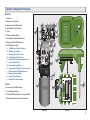
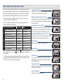
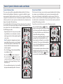
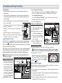
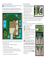
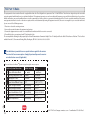
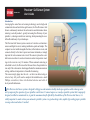
Precision Soil Sensor System
TM
Count on it.
User’s Guide
Introduction
Leveraging the same Toro soil-sensing technology used on high-end
commercial sites and world-class golf courses, the Toro Precision™ Soil
Sensor continuously monitors the soil moisture and determines when
watering is actually needed – greatly increasing the efficiency of your
sprinkler , reducing wasteful over-watering, while promoting the overall health and beauty of your landscape.
The Precision Soil Sensor system consists of a wireless soil moisture
sensor and digital receiver, making installation quick and simple. The
compact receiver installs alongside the timer, either indoors or out, and
connects directly to the timer’s power and sensor terminals, or simply
taps into the valve common wire circuit. The sensor is placed in a suitable lawn area where it sends soil moisture and air temperature readings to the receiver every 10 minutes. When automatic watering is
scheduled to start, the Precision Soil Sensor allows the sprinklers to
run only if the soil moisture has dropped below the minimum moisture
setting, and the air temperature is favorable for watering.
The sensor simply plugs into the soil – so there’s no holes to dig or
wires to bury. All you’ll need to complete the installation is a small
Phillips screwdriver, three AA alkaline batteries and a bit of
do-it-yourself enthusiasm.
The Precision Soil Sensor system is designed to help grow and maintain healthy landscape vegetation while reducing water
use by improving the operation of your sprinkler control timer. It cannot improve or remedy a sprinkler system that’s improperly
designed, installed or maintained. So, to gain the maximum benefit afforded by the addition of the Precision Soil Sensor, it is
vitally important to make certain your automatic sprinkler system is in good working order; capable of providing proper sprinkler
coverage–where and when it’s needed.
Table of Contents
Introduction . . . . . . . . . . . . . . . . . . . . . . . . . . . . . . . . . . . . . . . . . . . . . . .1
System Component Overview . . . . . . . . . . . . . . . . . . . . . . . . . . . . . 3
System Operating Modes . . . . . . . . . . . . . . . . . . . . . . . . . . . . . . . . . 4
• Normal Operating Modes . . . . . . . . . . . . . . . . . . . . . . . . . . . . . . . 4
•Watering Permitted . . . . . . . . . . . . . . . . . . . . . . . . . . . . . . . . . . . . 4
•Watering Restricted . . . . . . . . . . . . . . . . . . . . . . . . . . . . . . . . . . . . 4
• Smart Bypass Mode . . . . . . . . . . . . . . . . . . . . . . . . . . . . . . . . . . . . . 4
• Freeze Shut-off Mode . . . . . . . . . . . . . . . . . . . . . . . . . . . . . . . . . . . 4
System Status Indicators . . . . . . . . . . . . . . . . . . . . . . . . . . . . . . . . . . 5
• Warning Mode Indicator . . . . . . . . . . . . . . . . . . . . . . . . . . . . . . . . .5
•Restoring Operation . . . . . . . . . . . . . . . . . . . . . . . . . . . . . . . . . . . 5
• Battery and Signal Strength Indicators . . . . . . . . . . . . . . . . . . 5
System Calibration and Learn Modes . . . . . . . . . . . . . . . . . . . . . . 7
• System Calibration Mode . . . . . . . . . . . . . . . . . . . . . . . . . . . . . . . . 7
• Sensor Learn Mode . . . . . . . . . . . . . . . . . . . . . . . . . . . . . . . . . . . . . . 7
Installation and Setup Procedures . . . . . . . . . . . . . . . . . . . . . . . . . 8
• Install Receiver . . . . . . . . . . . . . . . . . . . . . . . . . . . . . . . . . . . . . . . . . . 8
• Connect Receiver to Timer . . . . . . . . . . . . . . . . . . . . . . . . . . . . . . 8
• Select Sensor Installation Site . . . . . . . . . . . . . . . . . . . . . . . . . . . 8
• Install Sensor Batteries . . . . . . . . . . . . . . . . . . . . . . . . . . . . . . . . . . 8
• Install Sensor . . . . . . . . . . . . . . . . . . . . . . . . . . . . . . . . . . . . . . . . . . . . 8
• Adjust the Automatic Watering Schedule . . . . . . . . . . . . . . . 9
Troubleshooting . . . . . . . . . . . . . . . . . . . . . . . . . . . . . . . . . . . . . . . . . 10
Specifications . . . . . . . . . . . . . . . . . . . . . . . . . . . . . . . . . . . . . . . . . . . . 11
Soil Moisture Adjustment . . . . . . . . . . . . . . . . . . . . . . . . . . . . . . . . . 5
• Fine-tuning the Soil Moisture Level . . . . . . . . . . . . . . . . . . . . . .5
Toro Commitment to Quality . . . . . . . . . . . . . . . . . . . . . . . . . . . . . 11
Advanced System Operations Menu . . . . . . . . . . . . . . . . . . . . . . . 6
• Smart Bypass Timer . . . . . . . . . . . . . . . . . . . . . . . . . . . . . . . . . . . . . 6
• Freeze Shut-off Temperature . . . . . . . . . . . . . . . . . . . . . . . . . . . 6
• Watering Completion Time . . . . . . . . . . . . . . . . . . . . . . . . . . . . 6
• Signal Strength . . . . . . . . . . . . . . . . . . . . . . . . . . . . . . . . . . . . . . . . 6
• Battery Voltage . . . . . . . . . . . . . . . . . . . . . . . . . . . . . . . . . . . . . . . . 6
• Sensor ID Code . . . . . . . . . . . . . . . . . . . . . . . . . . . . . . . . . . . . . . . . 6
• Air Temperature . . . . . . . . . . . . . . . . . . . . . . . . . . . . . . . . . . . . . . . 6
• Temperature Format . . . . . . . . . . . . . . . . . . . . . . . . . . . . . . . . . . 6
• Calibration Mode . . . . . . . . . . . . . . . . . . . . . . . . . . . . . . . . . . . . . . 6
FCC Part 15 Rules . . . . . . . . . . . . . . . . . . . . . . . . . . . . . . . . . . . . . . . . 12
2
Warranty . . . . . . . . . . . . . . . . . . . . . . . . . . . . . . . . . . . . . . . . . . . . . . . . . 11
System Operations Menu - Quick Reference . . . . . . . . . . . . . . 12
System Component Overview
Receiver
1 - Antenna
2 - Bypass Sensor Button
3 - Bypass Sensor LED Indicator
A
B
C
D
E
10
4 - Setup Menu Access Button
5 - Cover
F
L
1
6 - Connection Wire Cable
7 - Setup Menu Adjustment Buttons
G
K
8 - Watering Status LED Indicators
9 - LCD Display Symbols
A- Soil Moisture Control Indicator
B - Watering Suspended
C - Watering Completion Time
D- Smart Bypass Mode Active
E - Warning Mode (communication error)
F - System Setup Mode
G- Freeze Setting Indicator
H- Temperature Display Format Indicators
I - Alpha-numeric Display Characters
J - Battery Status Indicator
K - Signal Status Indicator
L - Bar Graph Status Indicator
Sensor
10 - Sensor Signal LED Indicator
J
I
H
9
8
2
3
13
7
4
6
AA
5
AA
11
12
11 - Soil Moisture Probes
12 - Size AA Alkaline Batteries - (not provided)
AA
13 - Battery Compartment Cover w/Screws
Receiver
Sensor
3
System Operating Modes
Normal Operating Modes
*Note: A value shown with an asterisk (*) indicates that it is the factory default
setting within an adjustable range. Refer to Advanced System Operations Menu
beginning on page 6 for detailed information regarding system settings and
adjustment options.
Watering Permitted
Smart Bypass Mode
When the Precision Soil Sensor is in the
Watering Permitted mode, the current soil
moisture
% value is displayed, and the Green LED is on.
In this example, the current soil moisture level
is 42%, which is below the *50% soil moisture
maintenance level, and watering is allowed.
The Smart Bypass feature enables the sprinkler system to operate while the Precision Soil
Sensor is in the Watering Restricted mode.
Note: If installation of the Precision Soil Sensor system has not been completed
or the system is not yet operational, refer to System Installation and Setup
procedures beginning on page 8.
Watering Restricted
Pressing the Bypass
button toggles
the Smart Bypass feature on and off. When
switched on, the Bypass mode will be automatically canceled in *24 hours, or it can be
manually canceled at any time.
When the soil moisture is above the *50% soil
moisture maintenance level, the Precision Soil
Sensor switches to the Watering Restricted
mode. A delay period of *4 hours begins
counting down before watering is actually
shut off. The delay period allows any remaining sprinkler zones in the watering cycle to
operate. The display will toggle between displaying the current soil moisture % value and
the amount of time remaining in the current
watering cycle completion period.
While the Precision Soil Sensor is in the Smart
Bypass mode, the Green LED will be on and
the Yellow LED will blink continuously. The
display will toggle between the current soil
moisture % value and the amount of time
remaining until the Watering Restricted mode
resumes. In this example the moisture level
is 85% and the Green LED is on. There are 24
hours remaining in the Smart Bypass mode.
In this example, the moisture level is 96%, and
the Green LED is on since watering will be
allowed to continue for 4 hours. The Watering
Restricted mode will begin immediately
following the watering cycle completion period. While in the Watering
Restricted mode, the current soil moisture % value with the No Watering
symbol will be displayed, and the Red LED will remain on.
Note: Ideally, one watering cycle should replenish the moisture level to 100%.
Watering program changes may be required to achieve this condition. Refer to
your control timer user’s guide for information regarding programming options.
If the sensor detects that air temperature has dropped to near freezing, the
Precision Soil Sensor automatically switches to the Freeze Shut-off mode
to restrict watering. When the temperature rises, the Freeze Shut-off mode
is canceled. Normal Operation mode will resume after the delay period set
by the Smart Bypass Timer.
4
Freeze Shut-off Mode
In this example, air temperature is detected
at the minimum setting of *39°F and watering
has been canceled. The Freeze temperature
and No Watering
symbols are displayed,
and the Red LED will blink continuously.
System Status Indications
Soil Moisture Adjustment
Warning Mode Indication
If the sensor does not communicate with
receiver within a 24-hour period, the Precision
Soil Sensor switches to the Warning mode,
indicated by all three LEDs blinking continuously. Watering will be permitted until the loss
of communication has been corrected.
Restoring Operation
Loss of communication can be caused by a damaged sensor, relocating
the sensor to different area of the yard, or a temporary obstruction, such
as a car or truck parked in the signal path. However, the most likely cause
is the sensor batteries have become too weak to provide adequate signal
strength.
If the sensor appearance and location is unchanged, and the signal path is
unobstructed, replace the sensor batteries with three new AA alkaline batteries. Press the Bypass
button to cancel the Warning mode. If communication is reestablished, the Precision Soil Sensor will automatically
resume normal operating mode within a short time.
Note: If the above measures do not restore normal operation, contact Toro
Customer Service for assistance at 1-877-345-8676.
Battery and Signal Strength Indications
The receiver display provides current battery and signal strength status
during all normal operating modes. The number of stacked bars that
appear with the corresponding antenna and battery display symbols,
indicate the current conditions as shown in the chart below.
Signal
Battery
6 Bars = Excellent
6 Bars = Excellent
4 Bars = Acceptable
4 Bars = Acceptable
2 Bars = Weak - Check Sensor
2 Bars = Weak - Replace Batteries
Landscape plants are the heartiest when their roots become established
several inches down where water is stored for the longest period of time.
Watering often, for short periods of time, promotes root growth near the
top of the soil, where the moisture evaporates quickly.
The key to maintaining healthy plants with minimum water waste is to
water thoroughly–only when it’s needed.
The Precision Soil Sensor is preset to restrict watering until the soil moisture level drops to 50% of capacity, or 1/2 of the total moisture that can be
retained in the soil. If you were
to draw a comparison to a
car’s fuel tank, 50% of the soil
Waste
100%
Capacity
moisture capacity would be
similar to using 1/2 of the fuel
Optimum
in the tank before stopping to
refill. A 50% setting restricts
50%
the sprinklers from refilling the
Stress
soil to capacity until 1/2 of the
moisture has been lost; causPermanent Wilt
ing the roots to go deeper for
0%
water. With the capability to
adjust the setting incrementally from 0% to 100%, the Precision Soil Sensor
can be fine-tuned for virtually any soil condition.
Fine-tuning the Moisture Level
Changes to the 50% setting should be made initially in 5% increments in
order to see results within a few days. The objective is to find the moisture
setting that results in a mild stress condition in the lawn, indicated by
slight wilting and dryness. At that point, adjust the setting 5% in the
opposite direction. This should result in moisture maintenance level that’s
very close to optimum.
• Press and release the Plus
button to display
the current setting (50 % by default).
• Press the Plus
button to increase, or the Minus
button to decrease the setting.
• Press Menu
button to return to the Normal
Operating mode.
5
Advanced System Operations Menu
The Advanced System Operations Menu lists a variety of operational settings and system status indicators. For most residential landscape applications, the default settings will provide good results. Each setting has a
range of adjustment enabling its function to be tailored as preferred.
• Press and release the Menu
button to step through the menu
sequence shown in the table below.
Note: If you step past a specific menu item, continue pressing the Menu
button to repeat the menu sequence.
Precision System Menu Item
Default Setting Range
System Calibration Mode
Automatic
Manual Reset
Watering Completion Time
4 Hours
0–24 Hours
Smart Bypass Timer
24 Hours
1–199 Hours
Freeze Shut-off Mode Temp
39°F
35–45°F (2–7°C)
Signal Strength Indicator
Review Only
0.0–10.0+
Battery Voltage Indicator
Review Only
0.0–4.5+
Sensor Identification Code
Review Only
00 00 00–99 99 99
Temperature Format Indicator °F
Sensor Temperature
Review Only
System Calibration Mode
Enables the sensor system to be manually calibrated for
current maximum soil moisture content.
Watering Completion Time (0–24 Hours)
Determines the amount of time allowed for a watering
cycle to be completed before the Watering Restricted
mode takes effect.
Smart Bypass Timer (1–199 Hours)
Determines the amount of time the system remains in
Smart Bypass mode (and after Freeze Shut-off mode)
before returning to the Normal Operating mode.
Freeze Shut-off Mode Temp (35–45°F or 2–7°C)
Determines the temperature that initiates the Freeze
Shut-off mode to suspend watering operation.
Signal Strength
Indicates signal strength in a digital format.
°F or °C
14° F –140° F+
• Where applicable, press the Plus
or Minus
buttons to adjust the
setting value.
• To exit the Advanced System Operations Menu, either press the Menu
button to display the Operating Mode screen, or allow the receiver
to idle for 10 seconds and exit automatically.
Battery Voltage
Indicates total voltage output of the sensor batteries.
Sensor ID Code
The Sensor Identification Code is displayed in three
number pairs, accessed by repeatedly pressing the
Plus or Minus button.
Temperature Format
Enables temperature format to be displayed in degrees
Fahrenheit or Centigrade.
Sensor Temperature
Indicates the sensor temperature.
6
Sensor System Calibration and Learn Modes
System Calibration Mode
Sensor Learn Mode
The sensor system will be automatically calibrated within 24–48 hours
after the initial installation. Calibration is required to establish the maximum amount of usable moisture in the soil. The sensor system will then
recognize this soil moisture level as the maximum capacity. From this fixed
reference point, the sensor system can decide when the soil moisture has
dropped enough to allow watering.
To manually calibrate the Precision Soil Sensor at any time, for example, if
the sensor has been moved to a different location in the landscape, or has
been replaced since the initial installation, use
the following procedure:
The Precision Soil Sensor receiver has been paired (matched) at the factory
to a unique sensor identification code, to prevent communication with
other sensors that may be installed within reception range. If either the
receiver or sensor is replaced, the frequency pairing procedure is required
to enable wireless communication. The receiver Learn mode is provided to
accomplish the pairing procedure.
• Approximately 2 to 4 hours prior to performing calibration, run an automatic or manual
watering operation to thoroughly irrigate the
sensor zone.
Note: The objective is to apply as much water
as possible to the sensor zone – up to the point
of runoff, then allow the soil drain down 2 to 4
hours to establish the maximum moistureretention capacity.
• Press the Menu
button to display CA (system calibration mode).
• Press the Minus
button to display 00.
To pair the receiver to the sensor, use the following procedure:
• Press and hold the Bypass
button
(without releasing) until the receiver switches
to the Learn mode and the display shows LE.
The Green LED will turn on, and the Red and
Yellow LEDs will begin blinking.
• If the sensor is operational (batteries installed),
paring will occur automatically the next
time a signal is sent from the sensor (within
10 minutes). The receiver will automatically
return to the Normal Operating mode when
communication is established.
• If the sensor batteries have not been installed,
automatic pairing will occur upon battery
installation. Press the Bypass
button
to return to the Normal Operating mode.
• Press and hold the Plus
button (several
seconds) until the Green LED indicator and
hourglass symbol begins flashing. The Red
LED will be on.
• The new calibrated moisture % value will be
displayed automatically within 10 minutes.
7
Installation and Setup Procedures
Install Receiver
• Position the receiver next to the timer (on the side opposite the timer’s
hinged cover).
• The receiver can be installed indoors using the mounting tape provided.
For outdoor installation, attach the receiver using the two stainless steel
screws provided.
• When installed outdoors, the receiver cover should remain closed when
access is not required.
1. Drive the top mounting screw into the wall, leaving
about 1/8” from flush.
Mounting Tape
2. Place the receiver on the screw using the key(Indoor Option)
hole slot.
3. Install and tighten the lower mounting screw.
4. Route the connection cable through the bottom of
the timer, into the wire connection area.
Connect Receiver to Timer
Note: If the timer is equipped with sensor terminals, continue at Step 1 below.
If the timer is not equipped with sensor terminals, continue at Step 1a. Refer
to your timer’s user guide for specific information regarding sensor installation
and Sensor control switch operation.
Note: When the receiver is connected to the timer’s sensor terminals, Rain Hold
will be indicated when the Precision Soil Sensor is actively restricting irrigation.
The Precision Soil Sensor does not replace or function as a Rain Sensor.
8
Red
Red
White
Caution: Ensure the timer’s power source is disconnected prior to connecting the receiver wires.
Setup for Timer With Sensor Timer Equipped with Sensor Terminals
1.Locate the Sensor connec- Remove Jumper Wire
PUMP
tion terminals. If the timer
1
2 3 4 MV COM SENSOR 24 VAC
has (or requires) a jumper
wire on the Sensor terminals connect the receiver
for Normally Closed (NC)
Red
operation. If a jumper wire To Sprinkler Valves or
Red
White
is not required, connect
Brown (NC)
the receiver for Normally
Yellow (NO)
Open (NO) operation.
2.For a Normally Closed Sensor:
Remove the jumper wire, and connect the Brown and White wires to
the Sensor terminals (in either position). The Yellow wire is not used.
For a Normally Open Sensor:
Connect the Yellow and White wires to the sensor terminals (in either
position). The Brown wire is not used.
3.Continue to Step 4 below.
Timer without Sensor Terminals Setup for Timer Without Sensor
1a.Remove the wire(s) connected
to the field Common terminal
(labeled COM or C).
2a.Using a twist-on wire connector, attach the Brown wire to
the wire(s) removed from the
Common terminal. The Yellow
wire is not used.
3a.Attach the White wire to the
Common (COM) terminal.
Common Setup (continued)
4.Attach the Red wires to the timer’s 24 VAC power terminals.
Caution: The receiver requires a source of 24 VAC continuous power
for operation. Severe damage will result if wired directly to 110/120 VAC.
5.Apply power to the timer.
Note: When the receiver is initially powered
up, the green LED will light, and the display will
show two bars with alternating Signal and
Battery symbols.
Adjust Watering Program
Review the timer’s automatic watering program and adjust as necessary to
provide the following watering schedule:
• Set watering to run every day of the week – with the exception of restricted
watering days.
• Set a run time duration for each zone that will provide thorough watering
– without causing pooling or runoff.
• Ensure an automatic watering cycle will run within 16 hours after initial
installation of the Precision Soil Sensor.
Install Sensor Batteries
Choosing the right location for the sensor is very important for the overall
effectiveness of the Precision Soil Sensor system.
The illustration below represents a typical residential landscape. The
blue sections indicate the areas that will receive the most direct sunlight
throughout the day may be considered for sensor placement.
• Remove four stainless Phillips screws
securing the sensor battery compartment cover. Place cover aside.
Note: The sensor requires three size
AA alkaline batteries for operation.
Batteries are not included.
• Install the batteries as shown.
• Install the battery compartment cover.
AA
AA
AA
Select the Sensor Installation Site
Note: When the sensor batteries are initially installed, the LED signal indicator is Red. When the receiver links with the sensor, the LED changes to Green.
The LED will remain on for 30 minutes to facilitate sensor installation.
Install Sensor
N
• Move the sensor to the proposed installation site. Signal strength is indicated by the LED color as follows:
Green = Excellent
Yellow = Acceptable
Red = Not Acceptable - Relocate Sensor
• With a suitable installation site selected,
thoroughly irrigate the sensor location and
surrounding landscape area by running a
manual watering cycle.
LED Signal
Indicator
Fescue Turf
Tall Fesque
• Trim the grass close to ground level where
the sensor will be placed.
From among the prospective lawn areas, select an installation site with the
following characteristics
• Is representative of the overall soil type and condition
• Is the highest elevation
• Is not over a septic tank or drain field
• Is well within receiver communication range (500’ line-of-sight)
• Is at least 4 feet away from a driveway, roof overhang or downspout
• Is not in a footpath or recreational area
• Is not exposed to overspray from nearby watering zones
Caution: For close-cut turf varieties,
such as Hybrid Bermuda, the top of the
sensor must be installed at grade level to
prevent damage by mowing equipment.
• Applying even, downward pressure on top
of the sensor, insert the sensor probes and
retention spikes completely into the soil.
• At the receiver, press the Bypass
to
place the Precision Soil Sensor in the Normal
Operating mode.
Hybrid Bermuda Turf
9
Troubleshooting
Solving Reception Problems
The Precision Soil Sensor system operates under Part 15 of the FCC rules.
This means that it has to comply with certain standards and is only allowed
to transmit up to a certain power level. In rating transmitters of any form,
typically a Line-of-Sight (LOS) value is used to show the relative effectiveness of a transmitter and allow a transmitter and receiver to be compared to
one another using a fair (apples to apples) method. The Precision Soil Sensor
has an effective operating range up to 500 feet LOS - meaning in an open
field, with no obstructions, the system will have a successfully communication range of up to 500 feet. However, in almost all installations, there are
obstacles between the sensor and receiver such as walls, floors, etc. These
obstacles will affect the signal reception and typically reduce the radiated
signal strength sent to the receiver. Different objects affect the transmitted
signal differently depending on the construction material, geometry, and
size. Typically, most residential construction materials do not reduce the
effective transmitted signal enough to pose problems under normal installation conditions. However there are some indoor installations with very thick
walls, or where radio frequency interference is high due to a nearby pump
motor or large electrical appliance.
To help resolve wireless communication problems:
• Install the sensor as close to the receiver location as possible to reduce the
potential for interference and signal reduction. If the signal strength is not
good in one location, try another appropriate location nearby - just moving the sensor a few feet can greatly improve signal strength.
• Interior locations where cell phones or cordless phones have trouble with
reception may indicate areas with poor RF signal transmission. The receiver can be installed outdoors and connected to the timer with extended
wire leads.
10
Specifications
Toro Commitment to Quality - Warranty
Receiver
Toro Commitment to Quality
• Receiver Mounting Options: Indoor or Outdoor (stainless steel screws
and double sided tape provided)
• Operating Temperature: 14° F –140° F
• Receiver Connection Cable: 36”, 24 AWG, 5-conductor, color-coded cable
• Receiver Power Input: 22–28 VAC/VDC, 100mA, from existing timer with
Class 2, UL-approved transformer
• Output Relay Contacts: Normally Open (NO) and Normally Closed (NC),
3A @ 24 VAC
• Receiver Material: High-impact ABS
• Operating Frequency: 915Mhz, DSSS (Direct Sequence Spread Spectrum)
• Agencies Approvals: UL and FCC
Toro is committed to developing and producing the highest quality, best
performing, most dependable products on the market. Because your satisfaction
is our first priority, we have provided the Toro Helpline to assist you with any
questions or problems that may arise. If for some reason you are not satisfied with
your purchase or have questions, please contact us toll free at 1-800-367-8676.
Sensor
• Power Supply: 4.5 VDC supplied by three size-AA alkaline batteries
• Housing Material: High-impact ABS
• Moisture Protection: Electronic circuitry encased in solid epoxy; battery
compartment sealed by O-ring
• Signal Quality Indicator: Tri-colored (Red, Yellow, Green) LED
• Stainless steel electrodes
• Built-in installation anchor stakes
Warranty
The Toro Company and its affiliate, Toro Warranty Company, pursuant to an
agreement between them, jointly warrants, to the owner, against defects in
material and workmanship for a period of one year from the date of purchase.
Neither The Toro Company nor Toro Warranty Company is liable for failure of
products not manufactured by them, even though such products may be sold or
used in conjunction with Toro products.
During such warranty period, we will repair or replace, at our option, any part
found to be defective.
Return the defective part to the place of purchase.
Our liability is limited solely to the replacement or repair of defective parts. There
are no other express warranties.
This warranty does not apply where equipment is used, or installation is
performed, in any manner contrary to Toro’s specifications and instructions, nor
where equipment is altered or modified.
Neither The Toro Company nor Toro Warranty Company is liable for indirect,
incidental or consequential damages in connection with the use of equipment,
including but not limited to: vegetation loss, the cost of substitute equipment or
services required during periods of malfunction or resulting non-use, property
damage or personal injury resulting from installer’s negligence.
Some states do not allow the exclusion or limitation of incidental or consequential
damages, so the above limitation or exclusion may not apply to you.
All implied warranties, including those of merchantability and fitness for use, are
limited to the duration of this express warranty.
Some states do not allow limitations of how long an implied warranty lasts, so
the above limitation may not apply to you. This warranty gives you specific legal
rights and you may have other rights which vary from state to state.
11
FCC Part 15 Rules
This equipment has been tested and found to comply with the limits for a Class B digital device, pursuant to Part 15 of the FCC Rules. These limits are designed to provide reasonable
protection against harmful interference in a residential installation. This equipment generates, uses and can radiate radio frequency energy and, if not installed and used in accordance
with the instructions, may cause harmful interference to radio communications. However, there is no guarantee that interference will not occur in a particular installation. If this equipment generates interference to radio or television reception, which can be determined by turning the equipment on and off, the user is encouraged to try to correct the interference
by one or more of the following measures:
1. Reorient or relocate the receiving antenna.
2. Increase the separation between the equipment and receiver.
3. Connect the equipment into an outlet on a circuit different from that to which the receiver is connected.
4. Consult the dealer or an experienced radio/TV technician for help.
The user may find the following booklet prepared by the Federal Communications Commission helpful: “How To Identify and Resolve Radio-TV Interference Problems”. This booklet is
available from the U.S. Government Printing Office, Washington, DC 20402. Stock No. 004-000-00345-4
The table below is provided to use as a quick reference guide for the various
Precision Soil Sensor menu options. Simply clip out and tape next to receiver
or inside the timer cover (if applicable).
Press and release the Menu
button to step through the menu sequence.
Precision System Menu Item
Default Setting Range
System Calibration Mode
Automatic
Manual Reset
Watering Completion Time
4 Hours
0–24 Hours
Smart Bypass Timer
24 Hours
1–199 Hours
Freeze Shut-off Mode Temp
39°F
35–45°F (2–7°C)
Signal Strength Indicator
Review Only
0.0–10.0+
Battery Voltage Indicator
Review Only
0.0–4.5+
Sensor Identification Code
Review Only
00 00 00–99 99 99
Temperature Format Indicator °F
#
Sensor Temperature
12
Review Only
°F or °C
14° F –140° F+
© 2012 The Toro Company • www.toro.com • Form Number 373-0604 Rev. 3
13
14