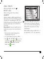
1
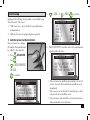
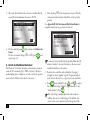
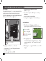
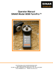
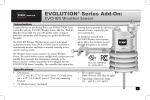
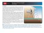
EVOLUTION® Series Add-On:
Precision™ Soil Sensor
Introduction
Congratulations on purchasing Toro’s new EVOLUTION®
controller with the Precision™ Soil Sensor add-on. With the
Precision™ Soil Sensor add-on, you will quickly realize savings
in both time and money while keeping your garden healthy
and beautiful.
Specifications
• Power Supply: 4.5 VDC supplied by three size-AA alkaline batteries
• Housing Material: High-impact, UV-resistant ABS
• Moisture Protection: Electronic circuitry encased in solid epoxy;
battery compartment sealed by O-ring
• Signal Quality Indicator: Tri-colored (Red, Yellow, Green) LED
• Stainless steel electrodes
• Built-in installation anchor stakes
• RF reception range: 500’ (152 m) LOS (line of sight)
• Operating Temperature: 14° F – 131° F (-10°C to +55°C)
Table of Contents
Specifications1
Overview3
Installation4
EVOLUTION® Smart Connect™
4
Precision™ Soil Sensor4
Battery Installation4
Sensor Setup5
Add the Sensor to the Controller
Install and Calibrate the Sensor
5
6
Soil Sensor Menu7
Navigating the Menu Interface
7
Getting to the Sensors Menu
7
Menu Settings8
Moisture Now8
Low Threshold8
Fine Tuning the Moisture Level
8
Signal Strength9
Battery Level9
Calibrate9
Cal Setting9
Current Temperature10
Freeze Off10
ID10
Appendix A: The Low Threshold Setting 11
Appendix B: Site Selection and Earth Installation
12
FCC Statement13
Toro Support14
2
Overview
The Precision™ Soil Sensor Add-On works with the EVOLUTION® Smart Connect™ receiver. It is possible to add up to three soil
sensors per controller.
LED Signal
Indicator
(sold separately)
3
Installation
EVOLUTION® Smart Connect™
Precision™ Soil Sensor
Battery Installation
The Soil Sensor works on three “AA” Alkaline or Lithium
batteries (not included).
1. Remove four Phillips screws securing the sensor
battery compartment cover (Figure 1). Set cover
aside.
2. Install the batteries (Figure 2).
3. Ensure the O-ring is in place then install the battery
compartment cover.
When batteries are initially installed, the LED
signal indicator is red. When the receiver links with
the sensor, the LED changes to green. The LED
will remain on for 30 minutes to facilitate sensor
installation.
4
2
Figure 1
3
4
Figure 2
AA
AA
AA
1
Implement the following two procedures to successfully setup
Toro’s Precision™ Soil Sensor:
1. “Add” the sensor to the controller for successful wireless
communication.
2. Calibrate the sensor for proper irrigation operation.
1. Add the Sensor to the Controller
Every soil sensor has a unique
ID number. That number must
be “added” to the controller.
ADVANCED
1. Press
then
to ADD/REMOVE
DEVICE.
to confirm.
→
ADVANCED
ZONE DETAILS
SCHEDULE STARTS
SCHEDULE DETAILS
SENSORS
ADD/REMOVE DEVICE
→
2.
.
3.
to SOIL 1.
to ADD.
to confirm.
ADD/REMOVE DEVICE
WS
ADD
ADD
SOIL 1
SOIL 2
ADD
SOIL 3
ADD
AUX 2
ADD
→
Sensor Setup
4. The EVOLUTION® controller waits for the identification
signal from the soil sensor.
ADD/REMOVE DEVICE
INSTALL BATTERY OR
WAIT FOR SIGNAL
MAY TAKE 30 MINUTES
CANCEL
• If the soil sensor has had batteries installed in the last 30
minutes, the controller should detect and add the sensor
immediately.
• If the sensor is out in the field, it could take up to a half
an hour to detect and add the sensor.
• One can remove and reinstall the soil sensor’s batteries to
achieve immediate sensor detection.
5
5. The controller will detect the soil sensor. Confirm that the
sensor ID detected matches the sensor’s SN ID.
ADD/REMOVE DEVICE
SOIL 1
DEVICE ID
05952
CORRECT?
YES
6. If it does match, press
and continue to Calibrate the
Sensor.
If it does not match, change YES to NO, press
, and
repeat steps 3-5.
2. Install and Calibrate the Sensor
The Precision™ Soil Sensor interprets soil moisture content on
a scale of 0% (extremely dry) to 100% (very wet). The key to
understanding how to calibrate a soil sensor is that the operator
must teach the 100% moisture level to the sensor.
1. After selecting YES from the previous screen, follow the
onscreen instructions below. Install the soil sensor in the
ground.
(See Appendix B: Site Selection and Earth Installation for
complete instructions on good sensor location.)
ADD/REMOVE DEVICE
INSTALL SENSOR
IN GROUND
SIGNAL STRENGTH
CONTINUE
If soil sensor is not installed in the ground within that 30
minute “window”, the controller removes the sensor and
installation will have to be redone.
2. Return to the controller and confirm that the signal
strength (see above graphic) is good. If signal strength is
weak, relocate the sensor to a spot closer to the controller.
3. Press
when satisfied.Use the
and
to adjust
the calibration setting (default 5: approximately a 1-day
“watch window”). Press
.
The “Cal Setting” number adjusts the time it takes to
calibrate the sensor. A Cal Setting of ‘0’ calibrates the
sensor to the current moisture level in the ground. The
6
calibration will be set using the next sensor reading
(within 30 minutes).
Additional calibration settings are available. From ‘1’ (~1
day “watch window”) to ‘168’ (~7 day “watch window”).
ADD/REMOVE DEVICE
CAL SETTING
5
The Soil Sensor Menu
The EVOLUTION® controller’s Soil Sensor menu displays
sensor information as well as allows the user to modify certain
settings.
Navigating the Menu Interface
• Use
or
to navigate the menu commands.
• To change a value, press
or
field, then press
and
CALIBRATE NOW?
YES
• Press
to input the desired value.
4. Move to the YES field after CALIBRATE NOW?
Press
. Sensor calibration begins.
Getting to the Sensors Menu
1. Press
ADVANCED then
5. Press
to return to the Home screen. A message on the
bottom of the Home screen indicates that the sensor is
calibrating. The message clears when calibration is finished.
2. Press
→
TUE
10/29
SCHEDULE A
NOT WATERING TODAY
SOIL 1 CALIBRATING
.
ADVANCED
ZONE RUNTIMES
ZONE DETAILS
SCHEDULE STARTS
SCHEDULE DETAILS
SENSORS
→
11:18AM
to SENSORS. Press
.
→
HOME
to move to the desired
to adjust the value.
7
3. Press
to select the desired soil sensor.
→
SENSORS
A
B
RAIN
-
WEATHER -
-
SOIL 1
SOIL 2 -
-
C
-
Sensors can be assigned to different schedules. In the above
screen, a rain sensor is assigned to schedule B and a soil
sensor to schedule A. Assigning a sensor to a schedule is
explained in the EVOLUTION® user manual, page 20.
4. Press
until the Soil Sensor menu appears.
→
SOIL SENSOR
MOISTURE NOW
100%
THRESHOLD
50%
LOW THRESHOLD
SIGNAL STRENGTH
BATTERY LEVEL
4.5V
CALIBRATE
START
Menu Settings
MOISTURE NOW
This displays the current moisture level, as a percentage, of the
soil. 100% is the soil level set after the first calibration
(see Calibrate the Sensor, page 6).
LOW THRESHOLD
This is the point at which the soil sensor will let the controller
resume irrigation of the landscape. If you were to compare the
soil to a gas tank, the “low threshold” would be the point at
which you refill the gas tank.
For a detailed explanation of the low threshold setting,
please read Appendix A of this manual.
Fine-tuning the “Low Threshold” Moisture Level
Changes to the 50% setting should be made initially in 5%
increments in order to see results within a few days. The
objective is to find the moisture setting that results in a mild
stress condition in the lawn, indicated by slight wilting and
dryness. At that point, adjust the setting 5% in the opposite
direction. This should result in moisture maintenance level
that’s very close to optimum.
1. Press
or
to increase or decrease the Low
Threshold point by 1%.
2. Press
8
to input the desired value.
SIGNAL STRENGTH
Indicates signal strength as a series of bars ( ).
BATTERY LEVEL
Indicates total voltage output of the sensor batteries.
CALIBRATE
1. Run an automatic or manual watering operation to
thoroughly irrigate the sensor zone.
2. Go to the Sensor Menu of the soil sensor to calibrate.
→
Calibration is required to establish the maximum amount of
usable moisture in the soil. The sensor will then recognize this
soil moisture level as the maximum capacity (100%). From
this fixed reference point, the sensor determines when the soil
moisture has dropped enough (to the “Low Threshold”) to
allow watering.
Manual calibration: At some point, it might be necessary to
recalibrate the sensor (in the event of a sensor relocation for
example).
SOIL SENSOR
LOW THRESHOLD
50%
SIGNAL STRENGTH
BATTERY LEVEL
4.5V
CALIBRATE
CANCEL
CAL SETTING
5
The “Cal Setting” number adjusts the time it takes to
calibrate the sensor. A Cal Setting of ‘0’ calibrates the
sensor to the current moisture level in the ground. The
calibration will be set using the next sensor reading
(within 30 minutes).
Additional calibration settings are available. From ‘1’ (~1
day “watch window”) to ‘168’ (~7 day “watch window”).
3. Press
to CAL SETTING. Use
to move to the
number field. Use
or
to adjust the calibration
number (default 5: approximately a 1-day “watch
window”). Press
to confirm.
9
4. Press
to CALIBRATE.
to confirm.
to START.
FREEZE OFF
Freeze Off is the temperature at which irrigation will be turned
off due to cold temperatures.
SOIL SENSOR
MOISTURE NOW
100%
LOW THRESHOLD
50%
SIGNAL STRENGTH
BATTERY LEVEL
4.5V
CALIBRATE
START
START
→
SOIL SENSOR
CALIBRATE
CAL SETTING
5
BYPASS
DISABLED
BYPASS TIMER
24HR
39°F
FREEZE OFF
CURRENT TEMP
Displays the temperature of the sensor at ground level (not at
“spike” level).
10
1.
or
raises or lowers the temperature value.
2. Press
to input the value.
ID
Displays the ID of the selected soil sensor.
SOIL SENSOR
FREEZE OFF
39F
CYCLE DELAY
4HR
ID
00 59 52
CURRENT TEMP
81°F
→
6. If you have not already directed the soil sensor to control a
schedule (EVOLUTION® user manual, page 20), please do
so now.
→
→
5. START will turn to CANCEL.
Over the specified time period (see note above), the soil sensor
will “learn” the 100% mark and transmit that information
to the controller. At the end of the time period, soil sensor
calibration is done.
Appendix A: The Low Threshold Setting
Landscape plants are the heartiest when their roots become
established several inches down where water is stored for the
longest period of time. Watering often, for short periods of
time, promotes root growth near the top of the soil, where the
moisture evaporates quickly.
100%
before stopping to refill. A 50% setting restricts the sprinklers
from refilling the soil to capacity until 1/2 of the moisture
has been lost; causing the roots to go deeper for water. With
the capability to adjust the setting incrementally from 0% to
100%, the Precision Soil Sensor can be fine-tuned for virtually
any soil condition.
Waste
Capacity
Optimum
50%
0%
Stress
Permanent Wilt
The key to maintaining healthy plants with minimum water
waste is to water thoroughly–only when it’s needed. The
Precision™ Soil Sensor is preset to restrict watering until the
soil moisture level drops to 50% of capacity, or 1/2 of the total
moisture that can be retained in the soil. If you were to draw
a comparison to a car’s fuel tank, 50% of the soil moisture
capacity would be similar to using 1/2 of the fuel in the tank
11
Appendix B: Site Selection and Earth Installation
Site Selection
Choosing the right location for the sensor is important for the
overall effectiveness of the Precision Soil Sensor system.
The below graphic represents a typical residential landscape. ‘X’
indicate good locations for sensor placement.
X
X
X
X
= good sensor location
For your garden, make sure the site selected is:
• representative of the overall soil type and condition
• the highest elevation
• not over a septic tank or drain field
12
• well within receiver communication range
(500’ line-of-sight)
• at least 4 feet away from a driveway, roof overhang or
downspout
• not in a footpath or recreational area
• not exposed to overspray from nearby watering zones
Earth Installation
1. Move the sensor to the proposed installation site.
Signal strength is indicated by the LED color as follows:
Green = Excellent
Yellow = Acceptable
Red = Not Acceptable Relocate Sensor
LED Signal
Indicator
2. Thoroughly irrigate the
sensor location and surrounding landscape area. This step
is crucial to establish the “100%” moisture level for sensor
calibration.
3. Trim the grass close to ground level where the sensor will
be placed.
!
For close-cut turf varieties, such as Hybrid Bermuda, the
top of the sensor must be installed at grade level to
prevent damage by mowing equipment.
Tall Fescue Turf
Hybrid Bermuda Turf
4. Applying even, downward pressure on top of the sensor,
insert the sensor probes and retention spikes completely
into the soil.
FCC Statement
This equipment has been tested and found to comply with the limits for
a Class B digital device, pursuant to Part 15 of the FCC Rules. These
limits are designed to provide reasonable protection against harmful
interference in a residential installation. This equipment generates, uses
and can radiate radio frequency energy and, if not installed and used
in accordance with the instructions, may cause harmful interference to
radio communications. However, there is no guarantee that interference
will not occur in a particular installation. If this equipment generates
interference to radio or television reception, which can be determined by
turning the equipment on and off, the user is encouraged to try to correct
the interference by one or more of the following measures:
1. Reorient or relocate the receiving antenna.
2. Increase the separation between the equipment and receiver.
3. Connect the equipment into an outlet on a circuit different from
that to which the receiver is connected.
4. Consult the dealer or an experienced radio/TV technician for help.
The user may find the following booklet prepared by the Federal
Communications Commission helpful: “How To Identify and Resolve
Radio-TV Interference Problems”. This booklet is available from the U.S.
Government Printing Office, Washington, DC 20402. Stock No. 004000-00345-4.
13
Toro Support
Toro Commitment to Quality
Toro is committed to developing and producing the highest quality, best
performing, most dependable products on the market. Because your satisfaction is our first priority, we have provided the Toro Helpline to assist
you with any questions or problems that may arise. If for some reason
you are not satisfied with your purchase or have questions, please contact
us toll free at 1-877-345-8676.
Warranty
The Toro Company and its affiliate, Toro Warranty Company, pursuant
to an agreement between them, jointly warrants, to the owner, against defects in material and workmanship for a period of one year from the date
of purchase. Neither The Toro Company nor Toro Warranty Company
is liable for failure of products not manufactured by them, even though
such products may be sold or used in conjunction with Toro products.
During such warranty period, we will repair or replace, at our option,
any part found to be defective. Return the defective part to the place
of purchase. Our liability is limited solely to the replacement or repair
of defective parts. There are no other express warranties. This warranty
does not apply where equipment is used, or installation is performed, in
any manner contrary to Toro’s specifications and instructions, nor where
equipment is altered or modified. Neither The Toro Company nor Toro
Warranty Company is liable for indirect, incidental or consequential
damages in connection with the use of equipment, including but not
limited to: vegetation loss, the cost of substitute equipment or services
required during periods of malfunction or resulting non-use, property
damage or personal injury resulting from installer’s negligence.
Some states do not allow the exclusion or limitation of incidental or
consequential damages, so the above limitation or exclusion may not
apply to you. All implied warranties, including those of merchantability
and fitness for use, are limited to the duration of this express warranty.
Some states do not allow limitations of how long an implied warranty
lasts, so the above limitation may not apply to you. This warranty gives
you specific legal rights and you may have other rights which vary from
state to state.
The Toro Company
5825 Jasmine Street
Riverside, CA 92504
14
©2013 The Toro Company, Irrigation Division • www.toro.com • 1-877-345-8676
Form Number 373-0807 Rev. A