1
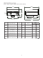
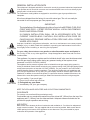
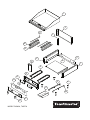
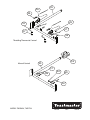
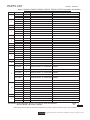
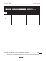
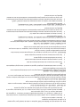
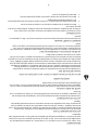
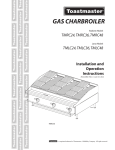
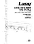
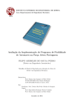
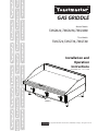
GAS GRIDDLE
Manual Models
TMGM24, TMGM36, TMGM48
T-Stat Models
TMGT24, TMGT36, TMGT48
Installation and
Operation
Instructions
2M-Z12966 Rev. - Oct. 1, 2009
IL1880
TMGM36
is a registerd trademark of Toastmaster, A Middleby Company. All rights reserved.
SAFETY SYMBOL
These symbols are intended to alert the user to the presence of
important operating and maintenance instructions in the manual accompanying the appliance.
RETAIN THIS MANUAL FOR FUTURE REFERENCE
NOTICE
Using any part other than genuine Toastmaster factory supplied parts relieves the
manufacturer of all liability.
Toastmaster reserves the right to change specifications and product design
without notice.Such revisions do not entitle the buyer to corresponding changes,
improvements, additions or replacements for previously purchased
equipment.
Due to periodic changes in designs, methods, procedures, policies and
regulations, the specifications contained in this sheet are subject to change
without notice. While Toastmaster exercises good faith efforts to provide
information that is accurate, we are not responsible for errors or omissions
in information provided or conclusions reached as a result of using the
specifications. By using the information provided, the user assumes all risks in
connection with such use.
MAINTENANCE AND REPAIRS
Contact your local authorized service agent for service or required maintenance.
Please record the model number, serial number, voltage and purchase date in the area below and have it
ready when you call to ensure a faster service.
Model No.
Authorized Service Agent
Reference the listing provided with the unit
Serial No.
Voltage
Purchase Date
or
for an updated listing go to:
Website:
E-mail Telephone:
www.star-mfg.com
[email protected]
(800) 807-9054 Local (314) 781-2777
The Service Help Desk
8:00 am to 4:30 p.m. Central Standard Time
Business
Hours:
(800) 807-9054 Local (314) 781-2777
Telephone:
Fax:
E-mail
Website:
(800) 396-2677 Local (314) 781-2714
[email protected]
[email protected]
[email protected]
Mailing Address:
2
www.star-mfg.com
Star Manufacturing International Inc.
10 Sunnen Drive
St. Louis, MO 63143
U.S.A
SPECIFICATIONS: Gas Griddle
MODEL: TMGM24, TMGM36, TMGM48, TMGT24, TMGT36, TMGT48
27 13/16
[70.6]
"Width"
5 1/2
[14.0]
15 17/32
[39.4]
1 13/16
[4.6]
5 5/16
[13.5]
4 - 5.375
5 29/32
[15.0]
"B"
19
[48.3]
29”
[73.7]
B = Width - 3.25”
Model
TMGM24
TMGM36
TMGM48
TMGT24
TMGT36
TMGT48
Height x Width x Depth
Grid Area
15.5” x 24” x 29”
498 sq. in
39.4cm x 61cm x 73.7cm
3213 sq. cm
15.5” x 36” x 29”
747 sq. in
39.4cm x 91.4cm x 73.7cm
4820 sq. cm
15.5” x 48” x 29”
996 sq. in
39.4cm x 121.9cm x 73.7cm
6426 sq. cm
15.5” x 24” x 29”
498 sq. in
39.4cm x 61cm x 73.7cm
3213 sq. cm
15.5” x 36” x 29”
747 sq. in
39.4cm x 91.4cm x 73.7cm
4820 sq. cm
15.5” x 48” x 29”
996 sq. in
39.4cm x 121.9cm x 73.7cm
6426 sq. cm
Controls
NAT / LP
2 Manual
NAT: 40,000 BTU/HR
3 Manual
NAT: 60,000 BTU/HR
4 Manual
NAT: 80,000 BTU/HR
2 T-Stat
NAT: 40,000 BTU/HR
3 T-Stat
NAT: 60,000 BTU/HR
4 T-Stat
NAT: 80,000 BTU/HR
IL1876
Weight
Installed
Shipped
147.4 lbs
157.4 lbs
66.8 kg
71.4 kg
220.5 lbs
235.5 lbs
100 kg
106.7 kg
294.7 lbs
314.7 lbs
128.67 kg
142.7 kg
147.4 lbs
157.4 lbs
66.8 kg
71.4 kg
220.5 lbs
235.5 lbs
100 kg
106.7 kg
294.7 lbs
314.7 lbs
128.67 kg
142.7 kg
GENERAL INSTALLATION DATA
CAUTION
This equipment is designed and sold for commercial use only by personnel trained and experienced
in its operation and is not sold for consumer use in and around the home nor for use directly by the
general public in food service locations.
The Toastmaster model griddles are equipped for use with the types of gas specified on the
nameplate.
All units are shipped from the factory for use with natural gas. The unit can easily be
converted for use on propane gas: See propane gas.
-IMPORTANTThe installation of the Appliance should conform to the NATIONAL FUEL GAS
CODE "ANSI Z223.1 - LATEST EDITION" AND ALL LOCAL GAS COMPANY
RULES AND REGULATIONS.
IN CANADA INSTALLATION SHALL BE IN ACCORDANCE WITH THE
CURRENT CAN/CGA-B149.1 NATURAL GAS INSTALLATION CODE OR
CAN/CGA-B149.2 PROPANE INSTALLATION CODE AND LOCAL CODES
WHERE APPLICABLE.
CAUTION
CAUTION
Improper installation, adjustment, alteration, service or maintenance can cause property
damage, injury or death. Read the installation, operating and maintenance instructions
thoroughly before installing or servicing the equipment.
For your safety, do not store or use gasoline or other flammable vapors and liquids in
the vicinity of this or any other appliance. Keep the appliance area clear and free from
combustibles.
This appliance, its pressure regulator and its individual shutoff valve must be disconnected
from the gas supply piping system during any pressure testing of that system at test
pressures in excess of 1/2 PSIG (3.45KPA).
This appliance and its pressure regulator must be isolated from the gas supply piping system by
closing its individual manual shutoff valve during any pressure testing of the gas supply piping system
at test pressures equal to or less than 1/2 PSIG (3.45KPA). For your protection, we recommend a
qualified installing agency install this appliance. They should be familiar with gas installations and
your local gas requirements. In any case, your gas company should be called to approve the final
installation. In addition, there should be posted, in a prominent location, detailed instructions to be
followed in the event the operator smells gas. Obtain the instructions from the local gas supplier.
For your safety, if you smell gas 1. Do not touch electrical switches.
2. Extinguish any open flame.
CAUTION 3. Immediately call your gas company.
KEEP THE APPLIANCE AREA FREE AND CLEAR FROM COMBUSTIBLES.
CLEARANCE
For use on non-combustible countertops only.
Combustible and non-combustible material must be at least 48" (120cm) from the top of the
appliance and 6" (150mm) from the sides and back. Adequate clearance should also be
provided for proper operation and servicing.
AIR SUPPLY
Make certain not to obstruct the flow of combustion and ventilation air. Provisions for adequate air
supply must be furnished. The legs supplied with the unit must be installed. Make certain that air
intake openings in the bottom of the appliance are not obstructed. They are essential for proper
combustion and operation of the appliance.
EXHAUST CANOPY
It is essential that facilities be provided over the griddle to carry off fumes and gases.
However, the unit should not be directly connected to a flue or stack.
LEVELING UNIT
This griddle is supplied with (4) feet which must be screwed into the legs attached to the
body. Level unit by adjusting the (4) feet which have an adjustment of 1-3/4" (43.75mm) for
accurate and perfect lineup with other units.
CAUTION DO NOT INSTALL WITHOUT ATTACHING FEET - DO NOT REMOVE FEET.
GAS PIPING
Gas piping shall be of such size and so installed as to provide a supply of gas sufficient to meet
the full gas input of the appliance. If the appliance is to be connected to existing piping, it shall be
checked to determine if it has adequate capacity. Joint compound shall be used sparingly and only
on the male threads of the pipe joints. Such compounds shall be resistant to the action of LP gases.
WARNING: Any loose dirt or metal particles which are allowed to enter the gas lines on this appliance
will damage the valve and affect its operation. When installing this appliance, all pipe and fittings must
be free from loose dirt.
GAS PRESSURE REGULATOR
A convertible pressure regulator is provided with each griddle. It should be connected to the inlet pipe
at the rear of the unit. The gas supply line is then connected to it. It is shipped set for 6" (15.24cm)
water column manifold pressure for use with natural gas.
MANUAL SHUT-OFF VALVE
A manual shut-off valve should be installed upstream from the union and within 6 feet (1.829m) of this
appliance.
PROPANE GAS
This griddle is equipped with fixed orifice hoods and is shipped from the factory for use on natural
gas. To convert to propane gas, install the burner orifice hoods, located in the grease drawer, as
follows:
1. Remove front panel by removing screws located on the front and the bottom.
2. Remove the burner(s) from the orifice hood(s). This is accomplished by removing the burner
mounting screw(s) and sliding the burner(s) off the hood(s).
3. Remove natural gas orifice hood(s) and install the propane hood(s) furnished.
4. Reinstall burner(s).
Note: TMGM & TMGT units use a #47 drill orifice for natural gas and a #55 drill orifice for
propane.
5. Reinstall front panel.
6. Remove the slotted, or hex-threaded, plug from the pressure regulator. Invert the plug and reinstall. The letters "LP" should now be visible on the plug. The regulator is now set for 10" (25.4cm)
water column.
7. Set manifold pressure to 10" (25.4cm) water column. A 1/8" pipe plug on the supply pipe can be
removed for attaching a pressure gauge.
CONNECTING GAS SUPPLY LINE
The gas inlet of the griddle is sealed at the factory to prevent entry of dirt. Do not remove this seal
until the actual connection is made to the gas supply line.
CHECKING FOR GAS LEAKS
Soap and water solution or other material acceptable for the purpose shall be used in locating gas
leakage. Matches, candle flame, or other sources of ignition shall not be used for this purpose.
Check entire piping system for leaks.
LIGHTING INSTRUCTIONS
When griddle is first lit, it will smoke until the preservation oils and impurities are burned off.
1. Turn off main valve to unit and wait 5 minutes to clear gas.
2. Turn off all knobs and pilot valves.
3. Turn on main valve and light all pilots.
4. Turn burner knobs to desired setting.
5. To turn burners off, turn knobs off.
NOTE: The griddles are equipped with standing pilots and should be lit immediately after
the gas is turned on.
Pilot flames can be lit and observed through the front panel view ports. However, best access for
lighting the pilot is from the bottom of the unit just behind the center wall.
PILOT LIGHT REGULATION
Adjust pilot light flames as small as possible, but high enough to light burner immediately when
burner valve is turned on high.
BURNER ADJUSTMENT (MODELS TMGM)
1. Remove the front panel.
2. Turn burner valve knob to "HI" position.
3. Close the air shutter on the front of the burner to give a soft blue flame having luminous tips and
open to a point where the yellow tips disappear and a hard blue flame is obtained. Repeat for all
burners.
BURNER ADJUSTMENT (MODELS TMGT)
1. Remove the front panel.
2. Push dial in and set thermostat of one burner to 450°F (229.9°C).
3. Close the air shutter on the front of the burner to give a soft blue flame having luminous
tips and open to a point where the yellow tips disappear and a hard blue flame is obtained.
Repeat for all burners.
BURNER OPERATION (MODELS TMGM)
To ignite burners, turn burner valve knob to "HI" position. Each burner is controlled by an individual
high-low, on-off valve. An infinite number of temperatures may be obtained by turning the burner valve
knob to any position between high and low. For overnight shutdown, turn the valves to the "OFF"
position.
SEASONING THE GRIDDLE SURFACE (NON-CHROMIUM SURFACES)
Clean the griddle surface thoroughly. After the griddle has been thoroughly cleaned, it should be
seasoned to prevent food from sticking. Before using, and after each thorough scouring, season the
griddle heating surface in the following manner:
1. Turn the temperature control dial to 350°F (174.9°C).
2. Using a clean cloth, not a spatula, spread a thin film of cooking oil over the griddle cooking surface.
This film should remain on the hot griddle surface 1/2 hour.
3. Remove excess oil and wipe clean.
4. Apply another film of cooking oil over the hot cooking area for another 1/2 hour and again remove
excess oil and wipe clean. The griddle surface should now be ready for use.
Even with careful seasoning food may, to some extent, stick to the griddle cooking
surface until griddle plate is "broken in."
COOKING (MODELS TD)
Set the thermostat dial knob to the temperature desired. After a short preheating period, the
thermostat will automatically maintain the selected temperature.
GREASE PAN
A grease pan is located at the front and can be removed for cleaning from the front. This pan should
be checked and emptied when necessary.
CAUTION
EXERCISE EXTREME CARE IN HANDLING THE GREASE PAN CONTAINING HOT
GREASE.
GRIDDLE CARE (NON-CHROMIUM AREAS)
It takes very little time and effort to keep the griddle attractive and performing at top efficiency.
If grease is permitted to accumulate, it will form a gummy cake and then carbonize into a hard
substance which is extremely difficult to remove. To prevent this condition, the following suggestions
for cleanliness should be followed:
1. After each use, scrape the griddle with a scraper or flexible spatula to remove excess grease and
food. A waste drawer is provided for the scrapings. If there is an accumulation of burned on grease
and food, the griddle should be thoroughly scoured and reseasoned. Use pumice or griddle stone
while the griddle is warm. Do not use steel wool because of the danger of steel slivers getting into
the food.
2. Daily-use a clean cloth and good non-abrasive cleaner to clean the stainless steel body of the
griddle. Wipe the polished front with a soft cloth.
3. At least once a day remove the waste drawer and wash in the same way as an ordinary cooking
utensil. The drawer is removed by pulling forward, up and out.
1
2
21
3
22
23
6
5
8
10
7
9
14
15
18
12
19
11
13
40
16
17
MODEL TMGM24, TMGT24
SK2429
REV -
8/26/09
25
39
38
29
33
27
37
28
Throttling Thermostat Control
Manual Control
24
20
27
26
29
28
30
MODEL TMGM24, TMGT24
SK2430
REV -
8/26/09
PARTS LIST
October 1, 2008, Rev -
MODEL: TMGM24, TMGM36, TMGM48, TMGT24, TMGT36, TMGT48 Toastmaster Gas Griddles
Fig No.
Part No.
Qty
Application
6
G3-Z5957
1
REAR PANEL
TMGM48
7
H4-Z12828
1
SIDE WALL, RIGHT ASSEMBLY
ALL
G3-Z5919
G3-Z5929
G3-Z5939
2F-Z5949
G3-624304
2A-Z0314
G3-Z6036
G3-Y7046
G4-Z12976
G3-Z12974
G4-Z12975
G3-Z5946
2R-Z13014
2R-Z13015
1
1
1
2/3/4
1
4
2
1
1
1
1
2/3/4
2/3/4
2/3/4
BOTTOM
BOTTOM
BOTTOM
BURNER
CHUTE ASSEMBLY
FOOT, 4” DIE CAST
DRAWER SLIDE
GREASE DRAWER
CENTER WALL 24”
CENTER WALL 36”
CENTER WALL 48”
BURNER COVER
KNOB
KNOB, T-STAT GAS
TMGM24, TMGT24
TMGM36, TMGT36
TMGM48, TMGT48
ALL
2M-Z12927
1
GRAPHIC PANEL, 24” CHAR/GRD TMGM24
2M-Z12930
1
GRAPHIC PANEL, 24” GRID
2M-Z12928
1
GRAPHIC PANEL, 36” CHAR/GRID TMGM36
2M-Z12931
1
GRAPHIC PANEL, 36” GRID
2M-Z12929
1
GRAPHIC PANEL, 48” CHAR/GRID TMGM48
2M-Z12932
G3-Z5976
G3-Z5977
G3-Z5978
G3-Z5979
G3-Z5980
G3-Z5981
VARIOUS
2K-Z5962
2K-Z5964
2K-Z5966
1
1
1
1
1
1
1
1
1
1
1
GRAPHIC PANEL, 48” GRID
FRONT PANEL
FRONT PANEL
FRONT PANEL
FRONT PANEL
FRONT PANEL
FRONT PANEL
NAMEPLATE
MANIFOLD
MANIFOLD
MANIFOLD
1
2
3
5
8
9
10
11
12
13
14
15
16
17
18
19
20
1
1
1
1
1
1
1
1
1
1
Description
G4-TC0008
G4-TC0007
G4-TC0009
G5-Z4812
G5-Z4813
G5-Z4814
G5-Z4817
H4-Z12829
G3-Z5953
G3-Z5955
TOP WELDMENT 24” GRIDDLE
TOP WELDMENT 36” GRIDDLE
TOP WELDMENT 48” GRIDDLE
FLUE 24”
FLUE 36”
FLUE 48”
FLUE DIVIDER
SIDE WALL, LEFT ASSEMBLY
REAR PANEL
REAR PANEL
TMGM24, TMGT24
TMGM36, TMGT36
TMGM48, TMGT48
TMGM24, TMGT24
TMGM36, TMGT36
TMGM48, TMGT48
TMGM36, TMGM48, TMGT24, TMGT48
ALL
TMGM24
TMGM36
ALL
ALL
TMGM24
TMGM24
TMGM36
TMGM48
ALL
TMGM24, TMGM36, TMGM48
TMGT24, TMGT36, TMGT48
TMGT24
TMGT36
TMGT48
TMGM24
TMGT24
TMGM36
TMGT36
TMGM48
TMGT48
ALL
TMGM24
TMGM36
TMGM48
IMPORTANT: WHEN ORDERING, SPECIFY VOLTAGE OR TYPE GAS DESIRED
INCLUDE MODEL AND SERIAL NUMBER
PAGE
OF
1
2
Some items are included for illustrative purposes only and in certain instances may not be available.
is a registerd trademark of Toastmaster, A Middleby Company. All rights reserved.
10
PARTS LIST
October 1, 2008, Rev -
MODEL: TMGM24, TMGM36, TMGM48, TMGT24, TMGT36, TMGT48 Toastmaster Gas Griddles
Fig. No
21
22
23
24
25
26
27
28
29
30
33
37
38
39
40
Part No
G3-GD0036
G3-Y9531
G3-Z4398
2J-Z0792
2K-Z5963
2K-Z5965
2K-Z5967
2V-Y8832
2V-Z6647
2V-6671
2P-1453
2J-Y7216
2J-Y7250
2K-Z4921
2A-9369
2K-Y7111
2T-Z4293
2C-8823
Qty
2/3/4
2/3/4
2/3/4
1
1
1
1
2/3/4
2/3/4
2/3/4
1
2/3/4
2/3/4
2/3/4
2/3/4
2/3/4
2/3/4
Various
Description
Application
TUBE-WASHER ASSY.
INSULATOR
BULB CLAMP
PRESSURE REGULATOR
MANIFOLD
MANIFOLD
MANIFOLD
VALVE-MANUAL GAS
PILOT BURNER
PILOT VALVE
PIPE PLUG 1/8NPT SQ HD
HOOD BURNER #47 NAT
ORIFICE #55 LP GRIDDLE
BURNER TUBE
ORIFICE FITTING
ELBOW 1/4 MBT X 3/8 CC
THERMOSTAT
SCREW #8 x 3/8
TMGT24, TMGT36, TMGT48
TMGT24, TMGT36, TMGT48
TMGT24, TMGT36, TMGT48
ALL
TMGT24
TMGT36
TMGT48
TMGM24, TMGM36, TMGM48
ALL
ALL
ALL
ALL
ALL
TMGT24, TMGT36, TMGT48
TMGT24
TMGT24, TMGT36, TMGT48
TMGT24, TMGT36, TMGT48
ALL
IMPORTANT: WHEN ORDERING, SPECIFY VOLTAGE OR TYPE GAS DESIRED
INCLUDE MODEL AND SERIAL NUMBER
PAGE
OF
2
2
Some items are included for illustrative purposes only and in certain instances may not be available.
is a registerd trademark of Toastmaster, A Middleby Company. All rights reserved.
11
Warranty Statement
This warranty is effective on all Toastmaster equipment sold on or after July 1, 2006, and supersedes all
previous warranties.
Toastmaster warrants equipment that it manufactures to be free from defects in material and
workmanship. Toastmaster’s obligation is limited to repairing or replacing, at Toastmaster’s option, without
cost to the customer, any part found to be defective, as well as any labor or material expense required to
replace the part.
Length of Warranty
This warranty is effective for a period of 18 months from the date of shipment from Toastmaster,
or 12 months from the date of purchase by the end user, whichever is earlier.
Exceptions
•
This warranty is valid only for the original end user owner/operator of the equipment.
•
This warranty does not apply to normal maintenance functions, including (but not limited to)
improper operation, installation or the use of an improper utility supply.
•
This warranty is valid only if the equipment is used in a commercial setting. The equipment
is designed and constructed for commercial use by trained professionals only. Any use of the
equipment in private or domestic applications immediately voids this warranty.
•
This warranty does not apply to any parts, labor and material expenses for service that is not
pre-approved and performed by a Toastmaster authorized service agent. Any such service
immediately voids this warranty.
•
This warranty does not apply to any parts, labor and material expenses associated with the
installation of parts that are not factory-approved for use in the equipment. Any use of such
parts immediately voids this warranty.
•
This warranty is not valid if terms of payment have not been met.
•
For warranty service on Pop-up toasters and light countertop equipment, an exchange program
would supersede a service call. Please find Warranty Exchange Program’ authorization to
follow. (http://www.toastmastercorp.com/filespdfcat/warranty_exchange_2008.pdf)
Toastmaster reserves the right to change the design and specifications of this equipment or any related
documentation at any time. The end user is not entitled to upgrades resulting from these changes.
This warranty is exclusive and supersedes all other warranties for the equipment, both expressed and
implied. There are no implied warranties of merchantability or of fitness for a particular purpose.
The foregoing is Toastmaster’s sole and exclusive obligation and the end user sole and exclusive remedy
for any action including breach of contract or negligence. In no event shall Toastmaster be liable for a sum
in excess of the purchase price of the equipment, or for any prospective or lost profits of the end user.
is a registerd trademark of Toastmaster, A Middleby Company. All rights reserved.
12
FONCTIONNEMENT DES BRÛLEURS (MODÈLES MD SEULEMENT)
Pour allumer les brûleurs, tourner le bouton du robinet du brûleur à la position "HI." Chaque brûleur
est commandé par un robinet individuel haut-bas, marche-arrêt. On peut obtenir un nombre infini de
températures en tournant le bouton du robinet du brûleur à une position entre haut et bas. Pour l'arrêt
durant la nuit, tournez les valves à la position de "OFF."
CONDITIONNEMENT DE LA SURFACE CHAUFFANTE DU GRIL (SURFACES NON
CHROMÉES)
Nettoyer soigneusement la surface du gril. Une fois bien nettoyé, le gril devrait être conditionné pour
empêcher les aliments de coller. Avant usage et après chaque nettoyage en profondeur, conditionner
la surface chauffante du gril de la manière suivante:
1. Tourner le cadran de contrôle de température à 174.9oC (350oF).
2. À l’aide d’un chiffon propre, et non d’une spatule, étendre une pellicule mince d’huile de cuisson ou
de matière grasse sur la surface de cuisson du gril. Cette pellicule doit demeurer une demi-heure
sur la surface chaude du gril.
3. Enlever l’excédent de graisse et essuyer.
4. Appliquer une autre pellicule d’huile de cuisson sur la surface de cuisson chaude pendant une
autre demi-heure, puis retirer à nouveau l’excédent de graisse et essuyer. La surface du gril devrait
maintenant être prête à usage.
Même avec un conditionnement soigné, les aliments peuvent, dans une certaine mesure,
adhérer à la surface de cuisson jusqu’à ce que la plaque du gril soit "rodée".
CUISSON (MODÈLES TDSEULEMENT)
Mettre le bouton du cadran du thermostat à la température désirée. Après une brève période de
préchauffage, le thermostat maintient automatiquement la température choisie.
BAC À GRAISSE
Le bac à graisse, situé à l’avant, peut être enlevé depuis l’avant pour le nettoyage. Ce bac doit être
vérifié et vidé au besoin.
MISE EN GARDE
REDOUBLER DE PRUDENCE EN MANIANT LE BAC À GRAISSE CONTENANT DE LA
GRAISSE CHAUDE.
ENTRETIEN DU GRIL (SURFACES NON CHROMÉES)
Il faut très peu de temps et d’efforts pour garder le gril attrayant et maintenir des prestations optimales.
Si on la laisse s’accumuler, la graisse forme une agglutination gommeuse pour ensuite se carboniser
en une substance dure qui est extrêmement difficile à enlever. Pour prévenir cette situation, les
mesures suivantes de propreté devraient être suivies:
1. Après chaque usage, racler le gril à l’aide d’une raclette ou d’une spatule flexible pour enlever
l’excédent de graisse et d’aliments. Un récipient à déchets est prévu pour les raclures. Si le gras
et les aliments deviennent excessivement calcinés, le gril doit être récuré soigneusement, puis
reconditionné. Utiliser une pierre ponce ou une pierre à gril pendant que le gril est chaud. Ne pas
utiliser de laine d’acier en raison du risque que des éclats d’acier pénètrent dans les aliments.
2. Tous les jours - utiliser un chiffon propre et un bon nettoyant non abrasif pour nettoyer le corps en
acier inoxydable du gril. Essuyer le devant poli à l’aide d’un chiffon doux.
3. Au moins une fois par jour, retirer le tiroir à déchets et laver de la même façon qu’un ustensile de
cuisson ordinaire. Le tiroir s’enlève en tirant vers l’avant, le haut et l’extérieur.
15
6
Note: Les unités de série de TMGM et de TMGT emploient un orifice du foret #47 pour le gaz naturel
et un orifice du foret #55 pour le propane.
5. Remettre le tableau avant en place.
6. Enlevez les emboîté, ou sort - enfilé, bouchez de le régulateur de la pression. Inversez le bouchon
et le ré installe. Les lettres " LP " devrait être maintenant visible sur le bouchon. Le régulateur est
maintenant mis pour 25.4 cm (10 po) colonne de l'eau.
7. Mettez la diverse pression à 25.4 cm (10 po) eau la colonne. Un 1/8 " bouchon de la pipe sur la
boîte de la pipe de la provision que soit enlevé pour attacher une jauge de pression.
LA RELIANT LIGNE DE LA PROVISION DU GAZ
L'entrée du gaz du grils est scellée à l'usine pour prévenir entrée de saleté. N'enlevez pas ce cachet
jusqu'à ce que le réel rapport soit fait à la ligne de la provision du gaz.
VÉRIFIER POUR LES FUITES DU GAZ
Savon et solution de l'eau ou autre matière acceptable pour le but, sera utilisé dans localiser la fuite du
gaz. Égaux, flamme de la bougie ou autres sources d'ignition ne seront pas utilisées pour ce but. Le
chèque système de la tuyauterie entier pour les fuites.
INSTRUCTIONS D’ALLUMAGE
Au premier allumage, le gril émettra de la fumée jusqu’à ce que les huiles de préservation et les
impuretés soient complètement brûlées.
1. Fermer la vanne d’alimentation principale à l’appareil et attendre 5 minutes jusqu’à disparition du
gaz.
2. Fermer tous les boutons et les robinets des flammes de veille.
3. Ouvrir la vanne principale et allumer toutes les flammes de veille.
4. Tourner les boutons de brûleur au réglage désiré.
5. Pour fermer les brûleurs, tourner les boutons à la position d’arrêt.
REMARQUE: Les grils sont équipés de lampes de veille permanentes et doivent être
allumés immédiatement après ouverture du gaz.
La flamme pilote peut être allumée et vue par le panneau avant. Cependant, le meilleur accès pour
allumer la lampe pilote est du fond de l'unité juste derrière le mur central.
AJUSTEMENT DES FLAMMES DE PILOTES
Mettre les flammes de veille à un réglage aussi bas que possible, mais suffisamment élevé pour
allumer le brûleur immédiatement lorsque le robinet du brûleur est ouvert à réglage élevé.
AJUSTEMENT DES BRÛLEURS (MODÈLES TMGM SEULEMENT)
1. Enlevez le panneau avant.
2. Tourner le bouton du robinet du brûleur à la position "HI."
3. Fermer le volet d’air de manière à donner une flamme bleue douce ayant des pointes lumineuses et
ouvrir jusqu’à un point où les pointes jaunes disparaissent et une flamme bleue dure est obtenue.
Répéter pour tous les brûleurs.
AJUSTEMENT DES BRÛLEURS (MODÈLES TMGT SEULEMENT)
1. Enlevez le panneau avant.
2. Pousser le cadran vers l’intérieur et mettre le thermostat d’un brûleur à 229.9oC (450oF).
3. Fermer le volet d’air de manière à donner une flamme bleue douce ayant des pointes lumineuses et
ouvrir jusqu’à un point où les pointes jaunes disparaissent et une flamme bleue dure est obtenue.
Répéter pour tous les brûleurs.
16
5
DÉGAGEMENT
Pour usage uniquement sur les comptoirs non combustibles. Les matières combustibles et non
combustibles doivent être à au moins 120 cm (48 po) du dessus de l’appareil et à 150 mm (6 po) des
côtés et de l’arrière. Un dégagement adéquat doit également être prévu pour le fonctionnement et les
réparations.
APPROVISIONNEMENT D’AIR
S’assurer de ne pas obstruer l’écoulement d’air de ventilation et de combustion. Des mesures
doivent être prises pour obtenir un approvisionnement d’air adéquat. Les jambes fournies avec l’unité
doivent être installées. S’assurer que les ouvertures d’admission d’air au bas de l’appareil ne sont
pas obstruées. Elles sont essentielles à une bonne combustion et au fonctionnement approprié de
l’appareil.
HOTTE D’ÉCHAPPEMENT
Il est essentiel de prendre des mesures au-dessus du gril pour l’échappement des fumées et des
gaz. Cependant, l’appareil ne doit pas être raccordé directement à un conduit d’évacuation ou à une
cheminée.
UNITÉ DE MISE À NIVEAU
Ce gril est pourvu de quatre pieds qui doivent être vissés dans les montants fixés au corps. On met
l’appareil à niveau en ajustant les quatre pieds qui ont un ajustement de 43.75 mm (1 3/4 po) en vue
d’un alignement exact et parfait avec les autres unités.
MISE EN GARDE
NE PAS INSTALLER SANS POSER LES PIEDS - NE PAS RETIRER LES PIEDS.
CANALISATION DE GAZ
La canalisation de gaz doit être de dimensions et installée de manière à assurer un approvisionnement de gaz suffisant pour répondre aux besoins de gaz de l’appareil. Si l’appareil doit être
raccordé à une canalisation existante, il faut la vérifier pour déterminer si sa capacité est adéquate.
Du mastic à joints doit être utilisé modérément et uniquement sur les filets mâles des joints de tuyau.
Ces mastics devront être résistants à l’action des gaz de propane liquéfié. MISE EN GARDE: Toute
particule lâche de saleté ou de métal qu’on laisse pénétrer dans la canalisation de gaz de cet appareil
abîmera le robinet et affectera son fonctionnement. En installant cet appareil, s’assurer que tous les
tuyaux et raccords sont exempts de saleté lâche.
LE RÉGULATEUR DE LA PRESSION DU GAZ
Un régulateur de la pression convertissable est fourni chaque plaque chauffante. Il devrait être relié
à la pipe d'entrée à l'arrière de l'unité. La ligne de la provision du gaz est reliée à lui alors. Il est
transporté résolu pour 15.24cm (6 po) colonne de l'eau diverse pression pour usage avec le gaz
naturel.
ROBINET D’ARRÊT MANUEL
Un robinet d’arrêt manuel doit être posé en amont du raccord et à moins de 1.829 m (6 pieds) de cet
appareil.
GAZ PROPANE
Ce gril est équipé de capots fixes et est expédié de l’usine pour usage sur le gaz naturel. Pour
convertir au gaz du propane, installez les capuchons de l'orifice du brûleur, localisés dans le tiroir de la
graisse, comme suit:
1. Retirer le tableau de commande en enlevant les vis situées à l’avant et en bas.
2. Retirer le(s) brûleur(s) du(des) capot(s). Ceci est accompli en enlevant les vis de support de brûleur
et en se glissant les brûleurs des capots.
3. Retirer le(s) capot(s) de gaz naturel et poser le(s) capot(s) de propane fourni(s).
4. Remettre le(s) brûleur(s) en place.
17
4
DONNÉES GÉNÉRALES D’INSTALLATION
MISE EN GARDE
Cet équipement est conçu et vendu pour usage commercial seulement par des employés formés
et expérimentés sur son usage, et il ne doit pas être vendu pour utilisation par des consommateurs
dans et autour de la maison ni pour usage directement par le grand public dans les établissements de
service alimentaire. Prière de se mettre en contact avec l’usine pour l’équipement devant être utilisé
par le grand public.
Les grils modèle Toastmaster sont équipés pour usage avec les types de gaz précisés sur la plaque
signalétique.
Tous les appareils sont expédiés de l’usine pour usage avec le gaz naturel. L’appareil peut facilement
être converti pour usage avec le propane: voir gaz propane.
-IMPORTANTL’installation de l’appareil doit se conformer au CODE NATIONAL DE GAZ
COMBUSTIBLE "ANSI Z223.1 - TOUTE DERNIÈRE ÉDITION" DES éTATS-UNIS ET
À TOUTES LES RÈGLES ET RÉGLEMENTATIONS DE LA COMPAGNIE DE GAZ
LOCALE.
AU CANADA, L’INSTALLATION DOIT ÊTRE CONFORME AU CODE COURANT
D’INSTALLATION AU GAZ NATUREL CAN/CGA-B149.1 OU AU CODE DE
INSTALLATION AU PROPANE CAN/CGA-B149.2 ET AUX CODES LOCAUX, LE
CAS ÉCHÉANT.
MISE EN GARDE
Des erreurs lors de l’installation, du réglage, de l’altération, des réparations ou de
l’entretien peuvent causer des dommages matériels, des blessures ou la mort. Lire
attentivement les instructions d’installation, d’utilisation et d’entretien avant d’installer ou
de réparer l’équipement.
MISE EN GARDE
POUR VOTRE SÉCURITÉ, NE PAS CONSERVER NI UTILISER DE L’ESSENCE OU
D’AUTRES VAPEURS ET LIQUIDES INFLAMMABLES À PROXIMITÉ DE CET APPAREIL OU
DE TOUT AUTRE APPAREIL. TENIR TOUT COMBUSTIBLE À L’ÉCART DE L’APPAREIL.
Cet appareil, son régulateur de pression et son robinet d’arrêt individuel doivent être débranchés du
système d’approvisionnement en gaz durant tout essai de pression de ce système à des pressions
d’essai de plus de 3.45 kPa (0.5 lb/po2). Cet appareil et son régulateur de pression doivent être isolés
du système d’alimentation en gaz en fermant son robinet d’arrêt manuel individuel durant tout essai
de pression du système d’approvisionnement en gaz à des pression d’essai égales ou inférieures à
3.45 kPa (0.5 lb/po2). Pour votre protection, nous vous recommandons de confier l’installation
de cet appareil à une agence d’installation qualifiée. Celle-ci doit connaître les installations au
gaz et les exigences de votre localité pour le gaz. L’installation définitive doit être soumise
à l’approbation de votre compagnie de gaz. En outre, on doit apposer, bien en vue, des
instructions détaillées à suivre dans l’hypothèse où l’opérateur sent une odeur de gaz. On peut
se procurer les instructions auprès du fournisseur de gaz local.
MISE EN GARDE
Si vous sentez une odeur de gaz 1. Ne touchez pas aux interrupteurs électriques.
2. Éteignez toute flamme nue.
3. Appelez immédiatement compagnie de gaz.
TENEZ TOUT COMBUSTIBLE À L’ÉCART DE L’APPAREIL.
18
3
SYMBOLE DE SÉCURITÉ
Ces symboles sont utilisés pour souligner à l’utilisateur les
instructions d’utilisation ou d’entretien importantes contenues
dans le manuel qui accompagne l’appareil.
CONSERVEZ CE MANUEL POUR RÉFÉRENCE FUTURE
AVIS
L’utilisation de toute pièce autre que les pièces d’origine STAR dégage le fabricant
de toute responsabilité.
Toastmaster se réserve le droit de changer les spécifications et la conception
du produit sans préavis. Ces changements ne donnent pas le droit à
l’acheteur d’obtenir les changements, améliorations, ajouts ou remplacements
correspondants pour l’équipement acheté préalablement.
Dû aux modifications périodiques de dessins, méthodes, procédures, règles
et régulations, les spécifications contenues dans ce manuel sont susceptibles
de changer sans préavis. Quoique Toastmaster exerce la bonne foi de fournir
le renseignement correct, Toastmaster n’est pas responsable pour les erreurs
ou les omissions dans le renseignement pourvu ou les conclusions tirées à la
suite de l’utilisation des spécifications. En utilisant le renseignement pourvu,
l’utilisateur assume tous les risques en relation avec telle utilisation.
ENTRETIEN ET RÉPARATIONS
Contactez votre détaillent local pour les réparations ou l’entretien requis. Assurez-vous d’avoir le numéro de
modèle, le numéro de série, le voltage et la date d’achat pour un service plus rapide. Entrez l’information
requise ci-dessous pour référence rapide.
Agent de service autorisé
Voir la liste pourvue avec l’appareil
Ou
Pour une liste mise à jour voir :
N° de modèle
N° de série
Voltage
Site web :
Courriel :
www.star-mfg.com
[email protected]
Date d’achat
2
19
GRILS A GAZ
Manual Modeles
TMGM24, TMGM36, TMGM48
T-Stat Modeles
TMGT24, TMGT36, TMGT48
Instructions
d’installation
et d’opération
2M-Z12966 Rev. - Oct. 1, 2009
IL1880
TMGM36
est une marque de Registerd Toastmaster, la Compagnie A Middleby. Tous droits réservés.
20