1
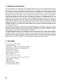
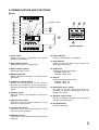
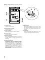
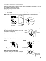
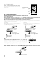
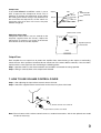
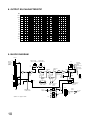
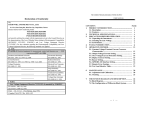
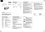
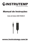
OPERATING INSTRUCTIONS
NEW 900 SERIES
IN-WALL MIXER POWER AMPLIFIER
W-906A
W-912A
900 SERIES
WALL AMPLIFIER
POWER
POWER
PEAK
AC FUSE OUTPUT FUSE
ON
OFF
250V 3A
COMPRESSOR
250V 6A
OFF
EQUALIZER
OUT
HIGH PASS
IN
63
125
OFF
250
500
ON
1k
2k
OFF
4k
ON
8k
16k
12
12
6
6
0
0
6
6
12
12
63
INPUT 1
MAX
LOW PASS
125
250
500
INPUT 2
1k
2k
4k
INPUT 3
8k
16k
INPUT 4
INPUT 5
INPUT 6
MASTER
TABLE OF CONTENTS
1. GENERAL DESCRIPTION ............................ 2
2. FEATURES .................................................... 2
3. NOMENCLATURE AND FUNCTIONS
Front .............................................................. 3
Front (viewed with the front cover removed) .... 4
4. INSTALLATION AND CONNECTION .......... 5
5. SERVICING .................................................... 8
6. OPERATION ................................................ 8
7. HOW TO USE VOLUME CONTROL COVER .... 9
8. OUTPUT EQ CHARACTERISTIC ............. 10
9. BLOCK DIAGRAM .................................... 10
10. SPECIFICATIONS ..................................... 11
Accessories ................................................ 12
Please follow the instructions in this manual to obtain the optimum results from this unit.
We also recommend that you keep this manual handy for future reference.
1. GENERAL DESCRIPTION
The TOA W-906A and W-912A Mixer Power Amplifiers control and mix up to six independent input signals
plus two inputs with use of expanding kit. The W-906A delivers up to 60 W of output power and the W-912A
120 W. Optional accessory modules are available for use with the W-906A and W-912A to provide versatility
for a wide range of operating applications. Edge connectors at the bottom of the front panel permit the
selection of the TOA plug-in modules: The H-01 series, H-02 series, H-03 series, H-21 and H-22 Microphone
Preamplifiers, the E-01 series and E-11 series Mag. Phono Preamplifiers, the X-01 series, X-11 series and X21 Auxiliary Preamplifiers for high-level sources, the B-01 series and B-11 series Bridging Transformers for
bridging high-impedance lines, the L-01 series Line Matching Transformers for matching 600 Ω lines, I-01
Paging Input for combining with TOA Intercom Systems EXES-1000, EXES-5000 and EX-16, T-01 series Line
Outputs for matching 600 Ω lines and the S-01, S-02 and S-03 Tone Signal Generators for generating
attention-getting signals and 1 kHz sine wave for testing within the total system. Other features include a
muting function. Sources fed to particular input module accessories are muted by short-circuiting at MUTE
TERMINALS on the front. To perform this function, Module E-11, X-11 series or B-11 series is required. Using
any of the modules H-21, H-22 and X-21 permits the input signal level to be controlled remotely by means of
an external potentiometer.
The W-906A and W-912A have a built-in one-octave graphic equalizer with 9 bands to tailor sound system
frequency response to room acoustics, reducing feed-back tendencies and improving intelligibility. A built-in
compressor circuit is provided to protect the output level from distortion as a result of excessive input and
keeps it constant. Compressor's threshold level can be adjusted.
The W-906A and W-912A Mixer Power Amplifiers have output terminals to match 4 or 8 Ω speaker systems,
or speaker distribution system may be connected to the 25 or 70 V terminals. User's (blank) space is provided
for additional functions to be made by the customers. The expanding kit (optional) may be loaded in this space
when the number of input is increased. Protection against tampering is assured by means of a key-locked
hinged door. The W-906A and W-912A can be mounted in any four-inch wall with of the BX-9F Flush
Mounting Black Box. On-wall mounting is also possible with the BX-9S Surface Mounting Box.
2. FEATURES
•
•
•
•
•
•
•
•
•
•
•
•
•
•
•
6-channel mixer power amplifier
Expandable to 8-input
Output power: 120 W for W-912A, 60 W for W-906A
Wide frequency response: 30 to 20,000 Hz ±1dB
Low distortion and noise
Excellent output regulation
Built-in one-octave equalizer
Built-in compressor
Self-protection circuitry design
Separate output terminals: 4 and 8 Ω, 25 and 70 V
Extra space for customizing
LED pilot light
LED peak indicator
Full range of plug-in modules
Flush and surface mounting
2
3. NOMENCLATURE AND FUNCTIONS
[Front]
900 SERIES
11
10
12
13
1
15
2
4
Equalizer Section
WALL AMPLIFIER
POWER
POWER
5
14
PEAK
AC FUSE OUTPUT FUSE
ON
OFF
250V 3A
6
EQUALIZER
OUT
COMPRESSOR
HIGH PASS
IN
63
125
7
OFF
250
500
ON
1k
2k
8
LOW PASS
OFF
4k
ON
8k
16k
12
12
6
6
250V 6A
0
OFF
EQUALIZER
OUT
HIGH PASS
IN
63
125
OFF
250
500
ON
1k
2k
4k
ON
8k
16k
12
6
6
0
0
6
16
6
12
12
63
125
250
500
INPUT 2
1k
2k
6
6
12
12
LOW PASS
OFF
12
INPUT 1
0
MAX
4k
INPUT 3
8k
63
125
250
500
1k
2k
4k
8k
16k
16k
INPUT 4
INPUT 5
INPUT 6
MASTER
9
3
1. Power switch
Applies line power. Two-position push button
switch for on-off modes.
2. Input volume controls
Adjust gain of input 1 – 6 respectively.
3. Master volume controls
Adjust overall gain of unit.
4. Modules (optional)
Select appropriate modules according to the
application.
5. Compressor control (limiter)
Setting the control switch to OFF position
bypasses the compressor circuit and turning it
clockwise will reduce the limiter level (will limit the
output).
6. Equalizer switch
Place this switch in the IN position to activate an
equalizer.
7. High-pass filter switch
Place this switch in the ON position to cut off
unnecessary low frequency.
Equalizer Section
10. Power indicator
Comes on when power is switched on.
11. Peak indicator
Comes on when the output signal reaches the
rated output power level.
12. Output fuse
Prevents excessive current flow.
W-906A: 250 V, 6 A
W-912A: 250 V, 10 A
13. AC fuse
Prevents excessive current flow.
W-906A: 250 V, 3 A
W-912A: 250 V, 5 A
14. Blank panel (user's space)
The space of 103 (w) x 63 (h) x 95 (d) mm is
provided. An optional expanding kit may be
loaded in this space.
15. Equalizer security cover
Prevents inadvertent changes of the equalizer
controls set at proper level.
16. Key-locked door
Prevents tampering.
8. Low-pass filter switch
Place this switch in the ON position to cut off
unnecessary high frequency.
9. Equalizer controls
9 band filters. 12 dB boots and cut at each center
frequency.
3
[Front] (viewed with the front cover removed)
18
17
19
20
POWER
AC FUSE OUTPUT FUSE
ON
OFF
250V 3A
COMPRESSOR
250V 6A
OFF
EQUALIZER
OUT
HIGH PASS
OFF
IN
ON
ON
125
250
500
1k
2k
4k
8k
16k
63
125
250
500
1k
2k
4k
8k
16k
12
12
6
6
0
0
6
6
12
INPUT 1
MAX
LOW PASS
OFF
63
12
INPUT 2
INPUT 3
INPUT 4
INPUT 5
INPUT 6
MASTER
21
22
23
Junction Box
24
17. AC power cord
Connects to power source.
18. Speaker output terminals
Connects to speakers.
19. Output terminals
Select output impedance with this terminal.
20. Low-cut switch
Cuts off unnecessary low frequency.
21. Module input ports
Accept PLUG-IN MODULES which are optionally
available. Module selection is determined by
application.
22. Bridging input/output
This terminal is used as a mixing bus. Mixing is
achieved when the similar terminal of another
amplifier is connected to this terminal. The output
level taken from this terminal is independent of
the all CONTROLS (except INPUT VOLUME
CONTROLS) so that the terminal can also be
used as recording output. The input impedances
of the equipment to be connected here should be
more than 10 kΩ.
4
23. Mute terminal
With modules employing muting function, which
are optionally available, the input signals fed to
the modules are muted by short-circuiting at this
terminal.
24. Cord clamp
Clamps off lead wires from module inputs, mute
terminals and bridging input/output terminals.
4. INSTALLATION AND CONNECTION
Installing this amplifier requires the optional back box, which is Model BX-9F for flush mounting in any 4 inch
wall and Model BX-9S for surface mounting.
Fix the back box first in installing the amplifier...
Installing Procedure
Step 1. Attach hinges to the back box by means of screws. (The hinges and screws are accessories supplied
free of change.)
Step 2. Fix the amplifier to the back box by inserting the amplifier bolts into the hinges as illustrated.
HINGE
POWER
AC FUSE OUTPUT FUSE
ON
OFF
250V 3A
COMPRESSOR
250V 6A
OFF
EQUALIZER
OUT
HIGH PASS
IN
OFF
ON
63
125
250
500
1k
63
125
250
500
1k
LOW PASS
OFF
ON
2k
4k
8k
16k
2k
4k
8k
16k
12
12
6
6
0
0
6
6
12
INPUT 1
MAX
12
INPUT 2
INPUT 3
INPUT 4
INPUT 5
INPUT 6
M3 x 6 mm
(6 pcs)
MASTER
Amplifier
(main chassis)
Back Box
BX-9F, BX-9S
From indoor wiring
Step 3. Connecting power cable
Be sure to make proper cable connections according to
color cording of the power cable.
After connection is completed, insulate sufficiently the
jointed sections and put them in a junction box.
BLACK
GREEN
WHITE
GREEN
WHITE
BLACK
Junction Box
Step 4. Attaching the junction box to the back box
The BX-9F differs from the BX-9S in the way to attach the junction box to the back box.
[BX-9F]
[BX-9S]
+ M3 x 10 screw (4 pcs)
+ M3 x 8 Tapping screw
(4 pcs)
Nut M3 (4 pcs)
SPEAKER TERMINAL
Step 5. Connecting the speaker cable
Connect the speaker cable to the speaker terminals on
the junction box. Amplifier output impedance may be
selected at the output terminals on the front panel.
SPEAKER CORD
Class 2 Wiring
may be used.
5
Step 6. Fixing the amplifier
Fix the amplifier to the back box with screws
after connecting the power cable and the
speaker cable.
M4 x 10 mm Screw
(3 pcs)
POWER
AC FUSE OUTPUT FUSE
ON
OFF
250V 3A
COMPRESSOR
250V 6A
OFF
EQUALIZER
OUT
HIGH PASS
IN
63
125
OFF
250
500
ON
1k
2k
ON
8k
16k
12
12
6
6
0
0
6
6
12
12
63
INPUT 1
MAX
LOW PASS
OFF
4k
125
250
500
INPUT 2
1k
2k
4k
INPUT 3
8k
16k
INPUT 4
INPUT 5
INPUT 6
MASTER
Step 7. Selecting output impedance
Select appropriate output impedance that matches the speaker to be used.
Class 2 wiring may be used.
Since these outputs consist of 8 Ω, 25 V and 70 V via the output transformer (matching transformer) and
direct output of 4 Ω, the connecting method differs in each case. See the following diagram.
Note: Impedances indicated below imply total speaker system (load) impedances.
• When connecting speakers to any one of the outputs of 8 Ω, 25 V or 70 V (BALANCED TRANSFORMER
OUTPUT); connect as illustrated below.
[W-906A]
[W-912A]
Change cable connection for required impedance
according to the speaker used.
Change cable connection for required impedance
according to the speaker used.
c
SPEAKER
OUTPUT
b a
c
OT
70V 25V 8Ω COM IN + 4Ω –
a 8Ω
SPEAKER
OUTPUT
b a
OT
70V 25V 8Ω COM IN + 4Ω –
Insert shorting bar
between 4 Ω + and OT IN
Insert shorting bar
between 4 Ω + and OT IN
a 8Ω
or
b 10.4 Ω (25 V line)
or
c 83 Ω (70 V line)
or
b 5.2 Ω (25 V line)
or
c 41 Ω (70 V line)
Note
In this case, the LOW-CUT SWITCH should be in "CUT" position. The
amplifier is characteristically flat even in the low frequency range.
Therefore, in TRANS OUTPUT, the acoustic effect and frequencyresponse characteristics may be altered. In TRANS OUTPUT, cut off
unnecessary low frequency to obtain the best acoustic condition.
CUT
FLAT
LOW-CUT
Place the LOW-CUT SWITCH
in "CUT" position
• When connecting speakers to the 4 Ω, output (UNBALANCED DIRECT OUTPUT); connect as illustrated
below.
4Ω
SPEAKER
OUTPUT
OT
70V 25V 8Ω COM IN + 4Ω –
Remove shorting bar
6
Step 8. Input connections
• This unit has six INPUT PORTS for plug-in modules. Select the desired modules for each application.
• Plug the modules into INPUT PORTS, sliding them between the guide rails, and secure each with two screws.
CAUTION
Modules should no be inserted or removed
while the amplifier is turned on.
• When not all INPUT PORTS are occupied, cover the vacant PORTS with back panels, and secure them with
screws.
• PLUG-IN MODULES are provided in the following:
Balanced low impedance microphone preamp. module (with presettable low-cut
filter, high-cut filter and gain controls)
H-01, H-21
Balanced low impedance microphone preamp. module (with presettable low-cut
filter, and gain controls)
H-02, H-22
Unbalanced high impedance microphone preamp. module (with presettable lowcut filter, high-cut filter and gain control)
H-03
Equalized mag. phono preamp. module (with presettable gain controls)
E-01, E-11
Unbalanced high impedance auxiliary preamp. module (with presettable gain
control)
X-01, X-11, X-21
Balanced 10 kΩ bridging transformer module
B-01, B-11
Balanced 600 Ω line matching transformer module
L-01
Balanced paging input module (with presettable gain control and MUTE Delay)
I-01
Balanced 600 Ω line output module (with presettable gain control)
T-01
Signal tone generator module (with presettable output level control)
· 1 kHz sine wave
· Yelp and buzzer
· One-tone chime and continuous one-tone chime
S-01
S-02
S-03
· With H-21, H-22 and X-21 modules employing volume remote control functions, connecting a
potentiometer (10 kΩ) to the terminal of any of these modules permits the sound volume to be remotely
controlled by means of the connected potentiometer.
· E-11, X-11 and B-11 modules incorporate muting functions. If a switch is connected to MUTE TERMINAL
on the rear panel of the amplifier and closed, these input signals can be muted.
· T-01 is used to feed out mixed signals to external equipment.
· T-01 should be inserted only in Input Port 5 or 6. (See the supplied "NEW 900 SERIES MODULES"
manual for details.)
Unite these cables to allow free rotation of the amplifier.
Note
Use modules with suffix "S" for standard input port.
7
Input Expander
The optional expanding kit (WE-2) is necessary to increase
the number of input. Up to two inputs may be added by
loading the expanding kit in the user's space. For details, refer
to the instruction manual of the kit.
CAUTION
Installation of optional items should be performed by a
qualified service personnel.
Expanding kit WE-2
Modules
Note
When the temperature of heat sink exceeds 105°C, the protection circuit is activated and the output is
disconnected from the circuit. The signal automatically begins to be output as the temperature goes down. In
such a case, confirm whether or not unit is overloaded or operated on an excessive output.
5. SERVICING
Unpacking
Upon receipt of the amplifier shipment, please incurred for any damage incurred in transit. If damage is found,
please notify your local TOA representative and the transportation company immediately.
State date, nature of damage, whether any damage was noticed on the shipping container, prior to unpacking.
Please give waybill number of shipping order.
Failure
Should amplifier fail, contact your nearest TOA authorized contractor or service center.
6. OPERATING
When all connections are completed, turn power switch on.
Then, the power indicator is illuminated. Approx. 5 seconds after switching power on, the amplifier comes into
operation.
Adjustment of Volume
Adjust the individual input and master volume controls to obtain appropriate output level.
When the peak indicator remains lit, reduce the sound volume to turn it off. If the system is operated with the
peak indicator lighting, it downgrades sound quality.
Adjusting graphic equalizer
The one-octave graphic equalizer tailors sound system frequency response to room acoustics, reducing feedback tendencies and improving intelligibility. Characteristic of this equalizer is as per below graph. Adjust it to
obtain the desired frequency response by actually hearing the sound or by using pink noise.
To make the adjustment, place the EQ switch in the IN position.
If a control knob is moved toward the plus (+) direction, center frequency is boosted and if toward the minus
(–) direction, it is cut. Placing the EQ switch in the OUT position bypasses the equalizer circuit and makes
frequency response flat.
Filter
When the HIGH PASS FILTER switch is in the ON position, low frequency is cut. In this event, low frequency
below 180 Hz may be cut at a 12 dB/OCTAVE rate. When LOW PASS FILTER switch is in the ON position,
high frequency of 7 kHz or higher may be cut at a 12 dB/OCTAVE rate.
To bypass the filter, place the filter in the OFF position.
8
Compressor
If the COMPRESSOR CONTROL switch is set to
OFF, it bypasses the compressor circuit. Turn it
clockwise to activate the compressor and to adjust
the limiting level. Since turing it fully clockwise far
too much limits the output level, set the switch at a
maximum point that does not cause the peak
indicator to light up.
OFF
Clip
Output
COMPRESSOR
CONTROL
HALF
Rated
MAX
1/2
Input
Release time control
Adjusting release time
Compressor release time is set at 2 seconds on the
amplifier supplied from the factory. Adjust the
release time, if necessary, by means of the release
time controls at the rear of the amplifier.
VR303
MIN
VR302
MAX
VR301
Equalizer printed
circuit board
CN302
Output Fuse
Each amplifier has an output fuse to protect the amplifier from short-circuiting at the output or overloading.
Check the fuse when speakers connected do not sound even if the meter deflects normally. If the fuse blew,
replace with the same type fuse after confirming the following points.
Step 1. Speaker cables are not short-circuited or the load does not exceed the rating specified.
Step 2. Wiring is correctly done at the output terminal board.
7. HOW TO USE VOLUME CONTROL COVER
Step 1. After adjusting the input volume control, remove its knob.
Step 2. Attach the supplied volume control cover to the chassis in place of the knob.
2
1
Volume control cover YA-910
Input volume control cover knob
Note: The unit comes with 3 volume control covers as standard accessories. Ask for the optional one model
YA-910 as necessary.
9
8. OUTPUT EQ CHARACTERISTIC
dB
+12
+10
+8
+6
+4
+2
0
–2
–4
–6
–8
–10
–12
20
50
100
200
500
1k
2k
5k
10k
20k
Hz
9. BLOCK DIAGRAM
+24V DC
#1
Module
Input Ports
–20dB V
(100mV)
10kΩ
High-pass filter
Low-pass filter
(180Hz,12dB/Oct.) (7kHz,12dB/Oct.)
on
off
OT
on
off
Equalizer
Out
In
Thermostat 105°C
COMP.
Unbalanced
Direct Output
4Ω
Output
Fuse
Low-cut
(60Hz,6dB/Oct.)
EQ
1
A
Peak
Indicator
Relay
Speaker
Output
Terminal
2
Relay
B
#6
Equarizer Control
63Hz – 16kHz
Mute
Bridging In/Out
–20dBV, 3.3kHz
250V
1A
PT
Power
Switch
Power
Indicator
+Vcc
0 dBV = 1 V = approx. 2 dBm
Protecting Circuit
• Output Muting
• DC Drift
Release Compressor
Time (Limiter)
Control
+24V DC
10
Compressor
(Limiter)
off
Power
Amp.
Master
Volume
Control
#5
Balanced
Transformer
Output
8Ω, 25V, 70V
–Vcc
AC
Fuse
AC 120V
60Hz
10. SPECIFICATIONS
Model No.
Type
Output Power
Power Bandwidth
Frequency Response
Total Harmonic Distortion
Inputs
Input Sensitivity/Impedance
Outputs
Output Regulation (1 kHz)
Signal to Noise Ratio
(Band Pass: 20 – 20,000 Hz)
Compression
Equalization
Filters
Controls
Indicators
Protection
Connectors
Power Consumption
Color
Dimensions
Weight
Other Features
W-906A
W-912A
Wall mounting 6-channel mixer power amplifier
60 W RMS
120 W RMS
(D): 20 – 20,000 Hz, 0.5% THD
(T): 20 – 20,000 Hz, 0.5% THD
(D): 30 – 20,000 Hz, ±1 dB
(T): 30 – 15,000 Hz, ±1 dB
(T): 30 – 20,000 Hz, ±1 dB, – 3 dB
0.02% at 1 kHz, rated output
Six input ports: Each port accepts any input module except T-01S.
Use T-01S only in port 5 or 6. One bridging input/output.
Input ports 1 to 6: 100 mV, 10 kΩ
Bridging input/output: 100 mV, 3.3 kΩ
(T): 8 Ω, 25 V and 70 V, balanced
(D): 4 Ω, unbalanced
(D): Less than 0.5 dB, no load to full load.
(T): Less than 1.0 dB, no load to full load.
Controls OFF:
90 dB
Master volume Max: 77 dB
Equalizer IN:
88 dB
Compressor IN:
84 dB
Attack time:
No greater than 2 milliseconds
Compression range: 20 dB
Release time:
Adjustable 20 – 2,000 milliseconds
Distortion:
Less than 1%
9-Band ISO One-octave graphic equalizer
Center frequencies: 63, 125, 250, 500, 1000, 2000, 4000, 8000, 16000 Hz
Equalization range: ±12 dB
High-pass filter: 180 Hz, 12 dB/octave
Low-pass filter: 7 kHz, 12 dB/octave
6 Input gain controls, 1 Master gain control, 1 Compression level control,
9 Equalizer controls, 1 Power ON/OFF switch, 1 Equalizer ON/OFF switch,
1 High-pass filter ON/OFF switch, 1 Low-pass filter ON/OFF switch,
1 Low-cut switch (60 Hz, 6 dB/octave, inside)
1 LED power indicator, 1LED peak indicator
Self-protection, with 2 AC fuses (1 inside) and 1 output fuse
Input 1 to 6:
Card-edge connector
Output:
Screw-terminal strip
Bridging input/output: Screw-terminal strip
Mute:
Screw-terminal strip
AC Power cord:
SJT 3-conductor
AC120 V, 60 Hz, 100 W
AC120 V, 60 Hz, 180 W
Silver
Face panel:
412 (w) x 680 (h) x 28 (d) mm
BX-9F Back Box: 362 (w) x 628 (h) x 98 (d) mm
BX-9S Back Box: 412 (w) x 680 (h) x 98 (d) mm
13.7 kg
17.3 kg
(without input modules and back box) (without input modules and back box)
Output disconnect for approx. 5 sec after power turned on.
Muting Function: Accomplished by input module X-11S, B-11S and E-11S.
* Power Bandwidth and Frequency Response are from input port to power amplifier output.
Note: The design and specifications are subject to change without notice for improvement.
11
• Accessories
Volume control cover .......................................... 3
Key (for door) ...................................................... 2
Lift-off hinge (receptacle) .................................... 2
Machine screw M4 x 10 ...................................... 5
Machine screw M3 x 6 ........................................ 6
Machine screw M3 x 10 ...................................... 4
Flange nut ........................................................... 4
Tapping screw 3 x 8 ............................................ 4
Inch screw ........................................................... 4
Indication label .................................................... 1
Instruction manual (W-906A/-912A) .................... 1
Instruction manual (New 900 series modules) .... 1
• Optional products
Flush-mounting (in-wall) back box:
BX-9F
Surface-mounting (on-wall) back box: BX-9S
Expanding kit:
WE-2
Volume control cover (black): YA-910
133-02-738-9B