1
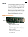
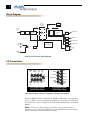
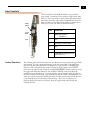
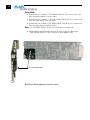
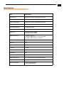
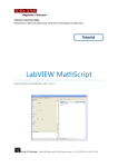
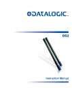
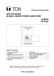
R20CE 10-bit Encoder
R-series Card Module
User Manual
August 25, 2003
P/N 101646-00
2
Trademarks
AJA, Io, and Kona are trademarks of AJA Video, Inc. All other trademarks are the property of their
respective holders.
Notice
Copyright © 2003 AJA Video, Inc. All rights reserved. All information in this manual is subject to
change without notice. No part of the document may be reproduced or transmitted in any form,
or by any means, electronic or mechanical, including photocopying or recording, without the
express written permission of AJA Inc.
FCC Emission Information
This equipment has been tested and found to comply with the limits for a Class A digital device,
pursuant to Part 15 of the FCC Rules. These limits are designed to provide reasonable protection
against harmful interference when the equipment is operated in a commercial environment. This
equipment generates, uses and can radiate radio frequency energy and, if not installed and used in
accordance with the instruction manual, may cause harmful interference to radio
communications. Operation of this equipment in a residential area is likely to cause harmful
interference in which case the user will be required to correct the interference at his own expense.
Changes or modifications not expressly approved by AJA Video can effect emission compliance
and could void the user’s authority to operate this equipment.
Contacting Support
To contact AJA Video for sales or support, use any of the following methods:
443 Crown Point Circle, Grass Valley, CA. 95945 USA
Telephone: +1.800.251.4224 or +1.530.274.2048
Fax: +1.530.274.9442
Web: http://www.aja.com
Support Email: [email protected]
Sales Email: [email protected]
When calling for support, have all information on the product (serial number etc.) at hand prior to
calling.
Limited Warranty
AJA Video warrants that this product will be free from defects in materials and workmanship for a period of five years from
the date of purchase. If a product proves to be defective during this warranty period, AJA Video, at its option, will either
repair the defective product without charge for parts and labor, or will provide a replacement in exchange for the defective
product.
In order to obtain service under this warranty, you the Customer, must notify AJA Video of the defect before the expiration
of the warranty period and make suitable arrangements for the performance of service. The Customer shall be responsible
for packaging and shipping the defective product to a designated service center nominated by AJA Video, with shipping
charges prepaid. AJA Video shall pay for the return of the product to the Customer if the shipment is to a location within
the country in which the AJA Video service center is located. Customer shall be responsible for paying all shipping charges,
insurance, duties, taxes, and any other charges for products returned to any other locations.
This warranty shall not apply to any defect, failure or damage caused by improper use or improper or inadequate
maintenance and care. AJA Video shall not be obligated to furnish service under this warranty a) to repair damage resulting
from attempts by personnel other than AJA Video representatives to install, repair or service the product, b) to repair
damage resulting from improper use or connection to incompatible equipment, c) to repair any damage or malfunction
caused by the use of non-AJA Video parts or supplies, or d) to service a product that has been modified or integrated with
other products when the effect of such a modification or integration increases the time or difficulty of servicing the
product.
THIS WARRANTY IS GIVEN BY AJA VIDEO IN LIEU OF ANY OTHER WARRANTIES, EXPRESS OR
IMPLIED. AJA VIDEO AND ITS VENDORS DISCLAIM ANY IMPLIED WARRANTIES OF
MERCHANTABILITY OR FITNESS FOR A PARTICULAR PURPOSE. AJA VIDEO’S RESPONSIBILITY TO
REPAIR OR REPLACE DEFECTIVE PRODUCTS IS THE WHOLE AND EXCLUSIVE REMEDY PROVIDED TO
THE CUSTOMER FOR ANY INDIRECT, SPECIAL, INCIDENTAL OR CONSEQUENTIAL DAMAGES
IRRESPECTIVE OF WHETHER AJA VIDEO OR THE VENDOR HAS ADVANCE NOTICE OF THE
POSSIBILITY OF SUCH DAMAGES.
AJA R20CE 10-bit Encoder User Manual — Introduction
Introduction
The AJA Video R20CE SDI to Analog Video Encoder produces high quality NTSC
or PAL 10-bit encoded video from SMPTE 259M SDI inputs. Three additional
analog outputs can be configured as duplicates of the composite output, or used for
component output. When configured for component video, the R20CE can output
Y/C (S-Video), YPbPr (SMPTE, EBU-N10), Betacam, or RGB.
The R20CE also serves as an SDI distribution amplifier, providing 2 re-clocked
outputs of the SDI input source. The R20CE is compatible with the AJA FRI IRU 4
slot frame or the FR2 2RU 10 slot frame.
The component and composite outputs incorporate optimum chroma filtering and
independent pedestal configuration. The R20CE also features an exclusive
1 PLL jitter
filter/memory to reduce the effects of SDI jitter on the output analog video. This
feature, along with the precision 4x oversampled D/A filters, provides high quality
analog outputs, with very low phase noise in the composite outputs.
The optional AJA model FSG (Frame Sync/Genlock) Module allows genlock to an
external reference with full timing adjustment. Without the FSG Module, the
reference input provides color frame timing.
Features
User
Controls
Timing
Adjustment
R20CE Card Module, Side View
• High quality 10-bit encoding, 4 times oversampling
• SDI Input, SMPTE 259M
• Two SDI outputs (SMPTE 259M) (equalized and re-clocked copies of the SDI
input)
• Four analog outputs (configurable as 4 composite, or 1 composite and R/G/B,
Y/Pb/Pr, or Y/C)i.
• Y/Pb/Pr selectable for SMPTE/EBU levels or Betacam levels (Y, R-Y, B-Y)
• Automatic NTSC/PAL selection
• Configurable pedestal and narrow/wide H/V blanking
• Frame Sync/Genlock option with reference input and full timing adjustment~
• Locks composite output Color Framing sequence to external reference without
Frame Sync/Genlock option,.
• Plug compatible with several other manufacturers' video frames
• Compatible with Leitch 6800 Series Frames
3
4
Block Diagram
Clock
Filter
Frame
Mezzanine
(optional)
27 MHz
27 MHz
27 MHz
Serial
Video
In
Cable
EQ
ReClock
Serial/
Parallel
FIFO
Encoder
Filter
COMPOSITE
Filter
COMP/_/G/Y
Filter
COMP/Y/B/B-Y
Filter
COMP/C/R/R-Y
Bypass
PIC
Microcontroller
REF
LOOP
1
Filter
Cable
Driver
Serial
Out
2
FRAME
REF
R20CE 10-bit Encoder, Block Diagram
I/O Connections
Comp/
C/R/Pr
Out
Comp/
G/Y Out
SDI In
SDI
Out 1
Ref
Loop
J1
SDI Out
SDI Out
J2
J3
Ref Loop
J8
J6
J4
J2
J9
J7
J5
J3
J1
Comp/
Y/B/Pb
Out
Comp Ref
Loop
Out
SDI
Out 2
FR1 Frame Layout
R20CE Rear Panel
Ref Loop
J4
SDI In
J5
Comp/G/Y Out
Comp Out
J6
Comp/
C/R/Pr
Out
J7
J8
J9
Comp/
Y/B/Pb
Out
FR2 Frame Layout
R20CE Rear Panel
FR1 and FR2 BNC Connector Assignments, R20CE Card Module
When the R20CE module is installed in an AJA FR1 or FR2 frame, a corresponding
group of 9 BNCs on the rear panel then provide I/O for the module. The illustration
above shows the connector assignments for both the FR1 and FR2 when used with the
R20CE.
Note: See the topic “External Reference Information” later in this manual for
information on use of the Ref Loop BNCs versus the FR1/FR2 frame reference BNC
when connecting an external reference video signal.
AJA R20CE 10-bit Encoder User Manual — User Controls
User Controls
Rotary
Switch
Control Functions
The user interface for the R20CE includes a 16 position hex
rotary switch, a momentary action up/down toggle switch, and 6
LEDs. Use the rotary switch to select a function and then adjust
the function using the toggle switch. The BANK Led allows two
banks of functions to be accessed, The LEDs are numbered 1-6
from top to bottom. The LEDs are labeled as follows:
LED
FUNCTION
Bank
Switch
1
BANK (OFF=Bank O
ON=Bank 1)
LEDs
2
525
3
AUTO (auto 525/625 select)
4
625
5
VID (video detected at input)
6
CONFIRM (for signaling memory
load, errors, etc.)
1
The following tables describe the functions controlled by the rotary switch and toggle switch
user interface. To access a particular function, set the hex rotary switch to the appropriate
function, and then adjust the function by flipping the toggle switch. For ON/OFF-type
functions, such as Setup/NoSetup selection, moving the toggle switch to the UP/LEFT
position sets the function and moving the switch DOWN/RIGHT clears the function. Using
the toggle with multi-value functions, such as INPUT MODE, rotates through all the
possible choices for the function. To control variables, such as framesync delay, the value of
the function will be incremented or decremented each time the switch is momentarily moved
either up, or down respectively. Holding the switch in either position will cause the function
to automatically begin incrementing or decrementing—after a two second pause. On
functions having more than two selections, using the toggle switch cycles through the
available selections.
5
6
Bank 0 Functions
FUNCTION
DESCRIPTION
DETAILS
0
BANK SEL
ToggleUP/LEFT to select BANK 1
Toggle DOWN/RIGHT to select BANK 0
1
|NPUT MODE
0 = Auto Select
1 = 525
2 = 625
2
VBLANK
UP/LEFT = Narrow
DOWN/RIG HT = Wide
3
SETUP
UP/LEFT = No Pedestal
DOWN/RIGHT=AddPedestal
4
OUTPUT MODE
0 = Composite on all
1 = Y,Pb,Pr
2 = RGB
3 = Y/C
5
COMPONENT
LEVELS
UP/LEFT = BETACAM 525 (Y, R-Y,B-Y)
DOWN/RIGI[T = SMPTE EBU N-10/
BETACAM 625 (Y,Pb,Pr)
(When OUTPUT MODE = Y,Pb,Pr)
6
INPUT SOURCE
0 = INPUT (pass video)
I = Ramp (Internal test signal)
2 = 100% Bars (Internal test signal)
3 = 75% Bars (Internal test signal)
7
<reserved>
8
CLEAR USER
SETUP
Toggle either way to clear User EEPROM
and reset board
9
RESET
Toggle either way to reset board
A
<reserved>
B
<reserved>
C
<reserved>
D
<reserved>
E
STORE/RECALL
Toggle UP to store register
Toggle DOWN to recall register
F
RESTORE
DEFAULTS
Toggle either way to restore default settings
AJA R20CE 10-bit Encoder User Manual — User Controls
Bank 1 (Frame Sync Option Only)
FUNCTION
DESCRIPTION
DETAILS
0
BANK SEL
Toggle UP/LEFT to select BANK I
Toggle DOWN/RIGHT to select BANK 0
|
SET DEFAULT
DELAY
Toggle UP/LEFT or DOWN/RIGHT =
Restores FSC to factory defaults
2
SET LINE DELAY
Toggle UP/LEFT = increases
OutputDelay by lines
Toggle DOWN/RIGHT = Decreases
Output Delay by lines
1
3
SET PIXEL DELAY
Toggle UP/LEFT = increases Output
Delay by pixels
Toggle DOWN/RIGHT = Decreases
Output Delay by pixels
4
<reserved>
5
<reserved>
6
<reserved>
7
<reserved>
8
<reserved>
9
<reserved>
A
<reserved>
B
<reserved>
C
<reserved>
D
<reserved>
E
STORE/RECALL
USER
CONFIGURATION
Toggle UP/LEFT to Store Register
Toggle DOWN/RIGHT to Recall Register
F
RESTORE
DEFAULTS
Toggle UP/LEFT or DOWN/RIGHT to
Restore Default Settings
7
8
Installation
Typically, R20CE installation consists of the following:
1.
2.
3.
4.
5.
disconnect power from the frame (remove line cord)
remove the FR1/FR2 front panel
install R20CE card module
apply external color black reference at the frame’s External Reference BNC
apply power to the frame by connecting a north american-style power cord from the
frame to mains power (90 to 260 VAC)
Instructions for removing the frame front door for module installation is discussed in the
FR1/FR2 User Manual.
External
Reference
Information
The R20CE expects the External Reference to be an NTSC or PAL analog Color Black
signal. The External Reference input can come from two different sources on the R20CE.
There are jumpers on the R20CE (see figure below) for selecting the external reference
source and for optionally terminating the selected reference source.
Looping Reference
The R20CE cell group of 9 BNCs contains two BNCs that can be used for a looping
reference connection. If this method is used, then the reference select setting on the R20CE
should be set to “LOOP” and the TERMINATION setting should be set to “OFF” (no
termination). Optionally, if you’re using only one of the looping reference BNCs, then the
TERMINATION setting should be set to “ON.”
Frame Reference
Alternatively, the R20CE installed in a FR1 or FR2 frame can use the frame’s frame reference
input BNC connector, which feeds an external reference video signal to all modules
installed in the frame. How the signal is distributed differs for the FR1 and FR2 frames.
Additionally, individual modules can usually be strapped as to whether external reference is
distributed from the frame or directly to BNCs on the module’s corresponding cell group
(the 9 BNCs on the rear panel).
FR1 Frame: the external reference signal is distributed passively to all frame modules.
If you wish to use the frame reference, the R20CE should have “FRAME”
reference selected on the module strapping, and one and only one card in the
frame should have “TERMINATION” set to “ON.” All other cards in the frame
should have TERMINATION set to “OFF.”
FR2 Frame: the external reference signal is distributed by an in-frame distribution
amplifier to all frame modules. This system terminates the Frame Reference
input BNC and buffers the signal to all slots. If using frame reference, the
R20CE installed in the FR2 frame should have “FRAME” set for reference select,
and all cards should have TERMINATION set to “OFF.”
AJA R20CE 10-bit Encoder User Manual — Installation
Front of Card
Reference Select:
FRAME = Selects Aux BNC on Frame
LOOP = Selects Reference Loop BNC
on Card Module Connectors
Termination:
OFF = No Termination
ON = 75 Ohm Internal Termination
1
FRAME
Reference Strapping
Field (J3)
LOOP
J3
OFF
ON
Jumpers shown with Reference Select set to “LOOP”
and Termination set to “OFF”
Reference Select and Termination Configuration
Output Timing
Adjustment (With
Model FSG
Framesync/
Genlock Option
The following procedure provides instructions for output timing adjustment of the R20CE
when used with the model FSG FRAMESYNC/GENLOCK option.
The R20CE has three levels of output timing adjustment:
• advance or delay by lines
• advance or delay by pixels (with l/4 pixel resolution)
• fine timing adjust (+/- 40 nanoseconds)
There are two modes of timing adjustment:
• Genlock
• Delay
If the R20CE detects an external reference, it then enters Genlock mode. If no external
reference is detected, the board enters Delay mode. In Genlock mode, the R20CE output
genlocks to the external reference. The board can be set to Delay mode without removing the
external reference by lifting the "REFERENCE SELECT" jumper (J3).
Genlock Mode
1. Perform function 1 in Bank 1 "SET DEFAULT DELAY." This brings the output
timing close to the reference's timing.
2. Perform function 3 in Bank 1 "SET PIXEL DELAY." This will allow adjustment to
within l/4 pixel of reference.
3. Adjust the "FINE TIMING ADJUST" control on the front of the R20CE board for
precise exact timing (refer to photo provided).
9
10
Delay Mode
1. Perform function 1 in Bank 1 "SET DEFAULT DELAY." This action sets the total
delay through the R20CE to about 1 frame.,
2. Perform function 2 in Bank 1 "SET LINE DELAY." This allows you to advance and
delay the output timing in line increments.
3. Perform function 3 in Bank 1 "SET PIXEL DELAY." This allows you to advance and
delay the output timing in Pixel increments.
Note: In "SET PIXEL DELAY," the first four increments are 1/4 pixel steps.
4. Adjust timing as desired anywhere between the steps set above by adjusting the
"FINE TIMING ADJUST" control on the front of the R20CE board.
Fine Timing Adjustment
R20CE Fine Timing Adjustment Control Location
AJA R20CE 10-bit Encoder User Manual — Specifications
Specifications
Item
Specification
Input Format:
SMPTE 259 / ITU-R-601 Serial Digital Component
Primary Output Format:
NTSC, PAL, Y/C (S Video)
Active Looping Output:
SMPTE 259 / ITU-R-601 Serial Digital Component
Reference Input Format:
NTSC or PAL Analog Color Black
SDI Cable Equalization:
300 meter 8281 typical
Serial Output:
Equalized, Re-clocked
Return Loss:
Serial Input:15 dB to 300MHz,
Serial Output:15 dB to 300MHz
FrequencyResponse:
+/- 0.25dB to 5.5MHz (Y)
+/- 0.25dB to 2.0Mhz (Chroma - Component, RGB)
+/- 0.25dB to 1.3Mhz (Chroma - Composite)
2T K factor:
<1% (Y)
Diff. Gain:
<1.5%
Diff. Phase:
<1.5 degree
Y/C delay:
l0 ns max
D/A Converters:
10 bits
Signal Path:
l0 bits
Delay (input to output):
6.2 microseconds (without Framesync option installed)
Output level matching:
1.5% or l0mv (All outputs are separately buffered)
Output level adjustment:
+/-20% (internal)
Power Consumption:
6.0 W (w/o FSG Framesync)
7.5 W (w/ FSG Framesync)
1
11
12