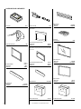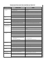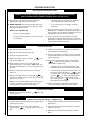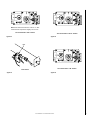
1
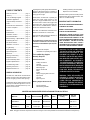
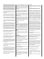
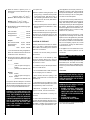
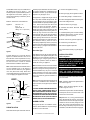
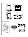
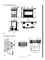
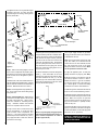
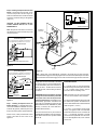
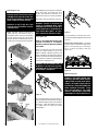
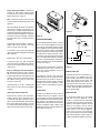
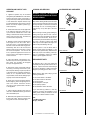
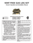
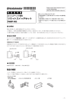
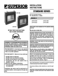
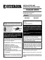
INSTALLATION AND
OPERATING INSTRUCTIONS
STANDARD SERIES
Unvented Decorative Gas Fireplaces
P/N 903571 REV. H 12/2007
MODELS
VFST-CMN-2
VFST-CMP-2
VFPF-CMN-2
VFPF-CMP-2
FOR USE ONLY WITH DECORATIVE TYPE UNVENTED ROOM
HEATERS.
INSTALLER: Leave this manual with the appliance.
CONSUMER: Retain this manual for future reference.
US
WARNING: IF THE INFORMATION IN THIS MANUAL
IS NOT FOLLOWED EXACTLY, A FIRE OR EXPLOSION MAY RESULT CAUSING PROPERTY DAMAGE,
PERSONAL INJURY OR LOSS OF LIFE.
FOR YOUR SAFETY: Do not store or use gasoline
or other flammable vapors or liquids in the vicinity
of this or any other appliance.
FOR YOUR SAFETY: What to do if you smell gas:
•
•
•
•
DO NOT light any appliance.
DO NOT touch any electrical switches.
DO NOT use any phone in your building.
Immediately call your gas supplier from a
neighbor’s phone.
Follow your gas suppliers instructions.
• If your gas supplier cannot be reached, call the
fire department.
Installation and service must be performed by a
qualified installer, service agency or the gas supplier.
DO NOT BUILD A WOOD FIRE.
WARNING: IMPROPER INSTALLATION, ADJUSTMENT, ALTERATION, SERVICE OR MAINTENANCE CAN CAUSE INJURY OR PROPERTY DAMAGE. REFER TO THIS MANUAL.
FOR ASSISTANCE OR ADDITIONAL INFORMATION CONSULT A QUALIFIED INSTALLER, SERVICE AGENCY OR THE
GAS SUPPLIER.
WARNING: DO NOT BURN WOOD OR OTHER MATERIAL IN
THESE APPLIANCES.
CAREFULLY REVIEW THE INSTRUCTIONS SUPPLIED WITH
THE DECORATIVE TYPE UNVENTED ROOM HEATER FOR
THE MINIMUM FIREPLACE SIZE REQUIREMENT.
DO NOT INSTALL THE APPLIANCE IN THIS FIREBOX, UNLESS THIS FIREBOX MEETS THE MINIMUM DIMENSIONS
REQUIRED FOR THE INSTALLATIONS.
This is an unvented gas-fired heater. It uses air
(oxygen) from the room in which it is installed.
Provisions for adequate combustion and ventilation air must be provided. Refer to Combustion
and Ventilation Air Section, Page 3.
Due to high temperatures, the appliance should be located out
of traffic and away from furniture or draperies.
Do not place clothing or other materials on or near this appliance.
IMPORTANT: READ AND UNDERSTAND THESE INSTRUCTIONS
COMPLETELY BEFORE INSTALLING YOUR UNVENTED ROOM
HEATERS.
NOTE: DIAGRAMS & ILLUSTRATION NOT TO SCALE.
1
TABLE OF CONTENTS
General Information ......................... page 2
Inventory ......................................... page 2
Tools and Building Supplies ............ page 2
Installation Applications .................. page 2
Important Safety Information .......... page 2
Codes .............................................. page 3
Combustion and Ventilation Air ....... page 3
Location of Fireplace ....................... page 4
Clearances ....................................... page 4
Preinstallation .................................. page 5
Installation – Built-In ....................... page 5
Finished Wall Details ....................... page 6
A spark ignition system (piezo) allows the heater
pilot gas to be lit without the use of matches or
batteries and permits operation of the heater
during a power outage.
These heaters are fitted with a specially designed pilot (ODS) which responds to the
amount of oxygen available in the room and
shuts the heater off before the oxygen level
drops below 18%. The pilot can be relit only
when fresh air is available. Refer to the Combustion and Ventilation Air section.
The VFST and VFPF Series Unvented Room
Heaters must be built into a framed wall.
This heater has been tested to the standards of
ANSI Z21.11.2 unvented heaters.
Electrical Wiring – Optional Blower . page 7
Connecting Gas Line ........................ page 7
Gas Pressure Check ......................... page 7
Do not install these unvented room heaters in
a bedroom or bathroom as all units exceed
maximum allowable BTU/Hr input of 10,000.
Installation – Surround .................... page 8
Log Assembly .................................. page 9
Flame Appearance ........................... page 9
Optional Equipment ......................... page 10
Blower Kit ........................................ page 10
Cleaning and Servicing .................... page 11
Inventory
Unvented Gas Fireplace
Installation and Operating Instructions
Tools and Building Supplies
Normally Required
Replacement Parts .......................... page 11
Accessories/Components ................ page 12
Appliance Specifications .................. page 13
Troubleshooting Guide .................... page 15
Operating Instructions ..................... page 16
Replacement Parts List .................... page 19
GENERAL INFORMATION
The VFST and VFPF Series Unvented Room
Heaters covered in this manual feature a unitized set of eight (8) ceramic fiber split logs.
These heaters have a standing pilot and may be
manually controlled through the use of an on/
off wall switch or wall thermostat or any combination of both of them.
Tools Should Include:
Phillips screwdriver
Hammer
Saw and/or Sabersaw
Measuring tape
Electric drill and bits
Pliers
Square
Piping complying with local codes
Pipe wrench
Tee joint
Pipe compound
Building Supplies Should Include:
Framing materials
Wall finishing materials
Caulking materials (noncombustible)
Fireplace surround materials
Check the inventory list to be sure that you have
all the necessary parts in usable condition. Also
check for concealed damage.
IMPORTANT SAFETY INFORMATION
INSTALLER: PLEASE LEAVE THESE INSTRUCTIONS WITH THE OWNER.
OWNER: PLEASE RETAIN THESE INSTRUCTION FOR FUTURE REFERENCE.
IMPORTANT: BEFORE STARTING YOUR
HEATER INSTALLATION, READ THESE INSTALLATION INSTRUCTIONS CAREFULLY TO BE
SURE YOU UNDERSTAND THEM COMPLETELY
AND IN ENTIRETY. FAILURE TO FOLLOW
THESE INSTRUCTIONS COULD CAUSE A
HEATER MALFUNCTION RESULTING IN SERIOUS INJURY AND/OR PROPERTY DAMAGE.
WARNING: FAILURE TO COMPLY WITH
THE INSTALLATION AND OPERATING
INSTRUCTIONS PROVIDED IN THIS
DOCUMENT WILL RESULT IN AN IMPROPERLY INSTALLED AND OPERATING UNVENTED ROOM HEATER, VOIDING ITS WARRANTY. ANY CHANGE TO
THIS HEATER AND/OR ITS OPERATING
CONTROLS IS DANGEROUS. IMPROPER
INSTALLATION OR USE OF THIS HEATER
CAN CAUSE SERIOUS INJURY OR DEATH
FORM FIRE, BURNS, EXPLOSION OR
CARBON MONOXIDE POISONING.
WARNING: THESE APPLIANCES ARE
DESIGNED TO OPERATE ON NATURAL
OR PROPANE GAS ONLY. THE USE OF
OTHER FUELS OR COMBINATION OF
FUELS WILL DEGRADE THE PERFORMANCE OF THIS SYSTEM AND MAY BE
DANGEROUS.
UNVENTED GAS ROOM HEATER SPECIFICATIONS AND TECHNICAL DETAILS
Gas Type
Maximum BTU/HR
Valve
Operation
VFST-CMN-2
VFPF-CMN-2
Natural
27,000 Low
34,000 High
VFST-CMP-2
VFPF-CMP-2
Propane/
LPG
27,000 Low
34,000 High
Model No.
Ignition
Regulator Pressure
Setting
Gas Inlet
Pressure
Millivolt with
Flame Control
Piezo
5" w.c.
Max 10-1/2" w.c.
Min. 6" w.c.
Millivolt with
Flame Control
Piezo
10" w.c.
Max 13" w.c.
Min. 11" w.c.
Note: Test gage connections are provided on the front of the gas control valve (identified A for the manifold side and E for inlet pressure).
2
NOTE: DIAGRAMS & ILLUSTRATION NOT TO SCALE.
Carbon Monoxide Poisoning: Early signs of
carbon monoxide poisoning are similar to the
flu with headaches, dizziness and/or nausea.
If you have these signs, obtain fresh air immediately. Turn off the gas supply to the
heater and have the Unvented Gas Heater
serviced as it may not be operating correctly.
• Due to high temperatures, the heater should
be located out of traffic and away from furniture
and draperies.
• Children and adults should be alerted to the
hazard of high surface temperatures and should
stay away to avoid burns or clothing ignition.
• Young children should be carefully supervised
when they are in the same room with the heater.
• Do not place clothing or other flammable
material on or near the heater for the purpose
of drying.
• Installation and repair should be done by a
qualified service person. The heater should be
inspected before use and at least annually by a
professional service person. More frequent cleaning may be required due to excessive lint from
carpeting, bedding material, etc. It is important
that control compartments, burners and circulating air passageways of the heater be kept clean.
• Allow the heater to cool before servicing.
Always shut off any electricity or gas to the
heater while performing service work.
• Do not install the VFST and VFPF series
heaters in a bedroom or bathroom.
• The installation must conform with local
codes or, in the absence of local codes with the
National Fuel Gas Code, ANSI Z223.1.
• The heater and its individual shut-off valve
must be disconnected from the gas supply
piping system while performing any tests of the
gas supply piping system at pressures in excess of 1/2 psig.
• Any safety screen or guard removed for
servicing the heater must be replaced prior to
operating the heater.
• The heater must be isolated from the gas
supply piping system by closing its individual
manual shut-off valve during any pressure testing of the gas supply piping system at test
pressures equal to or less than 1/2 psig.
• Keep heater area clear and free from combustible materials, gasoline and other flammable vapors and liquids.
• Do not use these appliances if any part has
been under water. Immediately call a qualified
professional service technician to inspect the
appliance and to replace any parts of the control
system and any gas control which have been
under water.
• Test gage connections are provided on the
front of the gas control valve (identified A for
the manifold side and E for inlet pressure).
• Input ratings are shown in BTU per hour and
are for elevations up to 7,000 feet. Operating
heater above elevations of 7,000 feet may cause
ODS pilot outage.
• Ensure that the heater is clean when operating. Excessive dust accumulation on the burner
and logs will increase the amount of carbon
monoxide formation and could lead to carbon
monoxide poisoning and death.
CODES
Adhere to all local codes or in their absence the
latest edition of The National Fuel Gas Code
ANSI Z223.1 or NFPA54 which can be obtained
from The American National Standards Institute, Inc. (1430 Broadway, New York, NY,
10018) or National Fire Protection Association,
Inc. (Batterymarch Park, Quincy, MA, 02269).
Massachusetts And New York Requirements
These appliances are approved for installation
in the following USA locations listed in the
following:
Massachusetts:
These fireplaces are approved for installation
in the US state of Massachusetts if the following additional requirements are met• Installation and repair must be done by a
plumber or gas fitter licensed in the Commonwealth of Massachusetts.
New York:
These fireplaces are approved for installation
in the US state of New York, but not in New
York city.
COMBUSTION AND VENTILATION AIR
These heaters shall not be installed in a confined space. The heater may be located in
unusually tight construction provided the
space is unconfined, or if confined, is provided with two permanent openings communicating directly with an additional room(s)
of sufficient volume so that the combined
volume of all connected spaces meets the
criteria for an unconfined space, (National
Fuel Gas Code ANSI Z223.1 (latest edition),
Section 5.3). Generally 50 ft 3 per 1,000 BTU
input of all operating appliances in the space.
The National Fuel Gas Code defines a confined space as a space whose volume is less
than 50 ft 3 per 1,000 BTU/Hr (4.8 m3 per kw)
of the aggregate input rating of all appliances
installed in that space and an unconfined
space as a space whose volume is not less
than 50 ft 3 per 1,000 BTU/Hr (4.8 m3 per kw)
of the aggregate input rating of all appliances
installed in that space. Rooms communicating directly with the space in which the appliances are installed, through openings not
furnished with doors, are considered a part of
the unconfined space.
Unusually tight construction is defined as construction where:
a. wall and ceilings exposed to the outside
atmosphere have a continuous water vapor
retarder with a rating or one perm or less with
openings gasketed or sealed, and
b. weather stripping has been added on operable windows and doors, and
• The individual manual shut-off must be a Thandle type valve.
c. caulking or sealants are applied to areas such
as joints around window and door frames,
between sole plates and floors, between wallceiling joints, between wall panels, at penetrations for plumbing, electrical, and gas lines,
and at other openings.
• Vent-Free appliances may NOT be installed in
bedrooms or bathrooms.
Use the following equations to determine if you
have a confined or unconfined space.
• A working smoke detector must be installed
in the area where vent-free appliances are
installed.
1. Determine the volume of space — ft 3.
• The flexible gas line connector used shall not
exceed 36 inches (92 centimeters) in length.
Seller of unvented propane or natural gasfired supplemental room heaters shall provide to each purchaser a copy of 527 CMR 30
upon sale of the unit.
NOTE: DIAGRAMS & ILLUSTRATION NOT TO SCALE.
Length x Width x Height = _____ ft 3
(Include adjoining rooms with doorless passageways or ventilation grills between
rooms.)
Example: 16' (L) x 16' (W) x 8' (H) = 2048 ft 3
3
2. Divide the volume of space by 50 ft 3 to
determine the maximum BTU/Hr the space
can support.
______ (volume of space – ft 3)/ 50 ft 3 =
(Maximum BTU/Hr the space can support)
Example: 3072 ft 3 / 50 ft 3 = 40.96
or 40,960 BTU/Hr the space can support.
3. Add the BTU/Hr of all the fuel burning appliances in the space.
Vent-Free heater
Gas appliance #1*
Gas appliance #2
_______
_______
+ _______
BTU/Hr
BTU/Hr
BTU/Hr
Total = _______
BTU/Hr
Example:
VFST Vent-free heater 32,000
Gas appliance #1
34,000
(water heater)
Total = 66,000
BTU/Hr
4. Compare the maximum BTU/Hr the space
can support with the actual amount of BTU/
Hr used.
_________ BTU/Hr
(max. the space can support)
_________ BTU/Hr
(actual amount of BTU/Hr used)
66,000
BTU/Hr
(max. the space can support)
BTU/Hr
(actual amount of BTU/Hr used)
The space in the above example is a confined
space because the actual BTU/Hr used is more
than the maximum BTU/Hr the space can support. You must provide additional fresh air.
WARNING: IF THE AREA IN WHICH THE
HEATER MAY BE OPERATED IS SMALLER
THAN THAT DEFINED AS AN UNCONFINED SPACE, PROVIDE ADEQUATE
COMBUSTION AND VENTILATION AIR BY
ONE OF THE METHODS DESCRIBED IN
THE NATIONAL FUEL GAS CODE, ANSI
Z223.1 1992, SECTION 5.3 OR APPLICABLE LOCAL CODES.
4
a. Rework equations adding the space of adjoining room(s). If the extra volume provides
an unconfined space, then remove door or
add ventilation grills between rooms. Refer
to National Fuel Gas Code, ANSI Z223.1
1992, Section 5.3.
b. Vent room directly to the outdoors. Refer to
National Fuel Gas Code, ANSI Z223.1 1992,
Section 5.3.
If the actual BTU/Hr used is less than the
maximum BTU/Hr the space can support, then
the space is an unconfined space. You will
need no additional fresh air ventilation for an
unconfined space.
LOCATION OF FIREPLACE
BTU/Hr
BTU/Hr
* Do not include direct-vent gas appliances.
Direct-vent is sealed combustion and draws
combustion air from the outdoors.
Example:
40,960
Your options are:
Carefully select the best location for installation of your VFST or VFPF series Unvented
Room Heater. The following factors should be
taken into consideration:
• Clearance to side wall, ceiling, woodwork
and windows.
• Location must not be affected by drafts
caused by kitchen exhaust fans, return air
registers for forced air furnaces/air conditioners, windows or doors.
• Installation must provide adequate ventilation and combustion air.
These appliances are uniquely suited for installations requiring a utility shelf positioned
directly above the fireplace. Utility shelves like
these are commonly used for locating television sets and decorative plants.
To provide for the lowest possible shelf surface, combustible materials used to support a
utility shelf directly above these appliances
should be positioned just above the appliance
top spacers. The minimum height from the
base of the appliance to the underside of combustible materials used to construct a utility
shelf is 43-1/4” (1099 mm).
The appliance should be mounted on a fully
supported base extending the full width and
depth of the unit. The appliance may be located
on or near conventional construction materials. However, if installed on combustible materials, such as carpeting, vinyl tile, etc., a metal
or wood barrier covering the entire bottom
surface must be used.
If the appliance is to be elevated above floor
level, a solid continuous platform must be
constructed.
WARNING: MAINTAIN MINIMUM
CLEARANCES.
Do not install in the vicinity of gasoline or other
flammable liquids. The heater must be kept
clear and free from these combustible materials and may not be located near where they are
stored.
• Do not install the VFST or VFPF series heaters in a sleeping room or bathroom.
Clearances
• Never obstruct the front opening of the
heater or restrict the flow of combustion and
ventilation air.
WARNING: DO NOT INSTALL VFST SERIES UNVENTED ROOM HEATERS IN
SLEEPING QUARTERS, OR IN RECREATIONAL VEHICLES.
• This appliance may be installed in an aftermarket* manufactured (Mobile) Home, where
not prohibited by state or local codes.
*Aftermarket: Completion of sale, not for
purpose of resale, from the manufacturer.
• Minimize modifications to existing construction.
To ensure even heat distribution, it is best to
position the heater centrally within the rooms.
Make sure there is adequate ventilation where
the heater is installed. The gas appliance will
shut off if the oxygen level falls below 18%.
NOTE: DIAGRAMS & ILLUSTRATION NOT TO SCALE.
WARNING: DO NOT INSTALL THE VFST
UNVENTED ROOM HEATER:
• WHERE CURTAINS, FURNITURE,
CLOTHING OR OTHER FLAMMABLE
OBJECTS ARE LESS THAN 42" FROM
THE FRONT OF THE UNVENTED ROOM
HEATER.
• IN HIGH TRAFFIC AREAS.
• IN WINDY OR DRAFTY AREAS.
Ensure the minimum clearances shown in Figures 1 and 2 are maintained.
Combustible mantles may be installed above
the appliance (as shown in Figure 2 ). The
mantle projection may be extended beyond 8" if
the height above the firebox opening is increased proportionately as detailed by the increments shown.
Minimum clearance to combustibles are:
Appliance:
each side - 1/2”
floor - 0"
adjacent wall - 0"
ceiling - 37-1/2” (953 mm)
0" Clearance
to Combustible
Side Wall
Max. Projection (See Figure 2)
Combustible
Mantel
37-1/2"
(953 mm)
Min. to
Ceiling from
Top of
Appliance
Door
(See Figure 2)
Carefully inspect the heater case and contents
for shipping damage and immediately inform
the dealer from whom you purchased the gas
fireplace if any damage is found.
A hearth extension is not required with this
appliance. If a hearth extension is used, do not
block the lower control compartment door. Any
hearth extensions used is for appearance only
and does not have to conform to standard
hearth extension installation requirements.
Note: Combustible wall finish materials and/or
surround materials must not be allowed to
encroach the area defined by the appliance
front face (black sheet metal). Never allow
combustible materials to be positioned in front
of or overlapping the appliance front face.
Combustible
Finished Wall
Materials
8''
(203 mm)
Header
This appliance can only be connected to the gas
type specified on the appliance data plate. This
appliance can not be modified in the field for a
different gas type. If the gas type to be used is
not the one specified contact the dealer to
obtain the correct gas appliance.
Note: Illustrations shown in this manual reflect
“typical” installations with nominal dimensions
and are for design and framing reference only.
Actual installations may vary due to individual
design preferences. However, always maintain
minimum clearances to combustible materials
and do not violate any specific installation requirements.
Note: The following steps represent the normal
sequence of installation. Each installation is
unique, however, and might require a different
sequence.
Spacer
21"
(533 mm)
2"
(50 mm)
14"
(356 mm)
Top of Appliance
Top of Door Frame
VF Series
Figure 2
PREINSTALLATION
2. Route gas supply line to appliance location.
3. Install nailing flanges. Install the hoods.
The appliance is shipped with all gas controls
and components installed and pre-wired. Remove the shipping carton, exposing the screen
panel assemblies or optional (if installed) glass
doors. Remove wood slats and remove and
discard the wood slat mounting brackets.
Loosen and remove the three (3) 1/4"-20 x 1"
Phillips pan head screws at the three (3) tabs
located along the top of the screen or glass door
frame top edge. Tilt the frame outward and
disengage the three (3) tabs along the bottom
from the three (3) brackets at the bottom of the
firebox opening. Remove the door and set the
panel aside protecting it from inadvertent damage. Retain the three (3) screws for use on
reassembly. Repeat the procedure (if required)
to gain access to the other side of the appliance.
Remove the logs, packaged inside the firebox
and also set aside.
Check Gas Type
Figure 1
1. Construct the appliance framing.
CAUTION: HEATERS CREATE WARM AIR CURRENTS. THESE CURRENTS MOVE HEAT TO
WALL SURFACES NEXT TO HEATER. INSTALLING HEATER NEXT TO VINYL OR CLOTH WALL
COVERINGS OR OPERATING HEATER WHERE
IMPURITIES IN THE AIR (SUCH AS TOBACCO
SMOKE) EXISTS, MAY DISCOLOR WALLS.
ASSEMBLY STEPS
The typical sequence of installation follows,
however, each installation is unique resulting in
variations to those described.
4. Position the appliance within the framing and
secure with nailing brackets.
5. Make connection to gas supply.
6. Assemble the Carbon Monoxide Safety
Shutoff (COSS).
7. Install the operating control switch and bring
in electrical service line for forced air circulating blower (optional equipment).
8. Mount forced air kit (optional equipment).
9. Install the logs and Rockwool.
10. Checkout appliance operation.
11. Install screen assembly or (optional) glass
door.
INSTALLATION STEPS
Built-In Systems
WARNING: DO NOT ALLOW FANS TO
BLOW DIRECTLY INTO THE FIREPLACE.
AVOID ANY DRAFTS THAT ALTER
BURNER FLAME PATTERNS.
WARNING: DO NOT USE A BLOWER INSERT, OR OTHER ACCESSORY NOT
APPROVED FOR USE WITH THIS HEATER.
Do not burn solid fuels in this listed unvented
gas room heater.
Note: Appliance Dimensional Specifications
are shown in Figure 3.
Step 1. Frame the VFST appliance as illustrated in Figures 4 and 5.
The header may be in direct contact with the top
metal spacers, but must not rest on them or be
notched to fit around them.
Step 2. Route a 1/2" (13 mm) gas line along the
left or right side framing (Figure 6 ). The primary
method for the SF is from the right end (when
viewed from the control side) straight in to the
valve. ST's may be routed as the PF's are, from
the left using an assembly composed of a 3/8"
street elbow, a 3/8" elbow and 3/8" 6" long nipple.
Check that all listed parts have been received.
NOTE: DIAGRAMS & ILLUSTRATION NOT TO SCALE.
5
VFST APPLIANCE SPECIFICATIONS
5-1/2"
(140 mm)
42-3/4"
(1086 mm)
31-3/4"
(806 mm)
37-1/4"
(946 mm)
20"
(508 mm)
4-1/2"
(114 mm)
J Box/Gas Line
Opening
(2 Places)
34"
(864 mm)
4"
(102 mm)
24"
(610 mm)
40"
(1016 mm)
42"
(1067 mm)
Left End View
Front View
(VFST)
5-1/2"
(140 mm)
31-3/4"
(806 mm)
3-1/8"
(79 mm)
5/8"
(16 mm)
12"
(504 mm)
Gas Line
Opening
18"
(458 mm)
4"
(102 mm)
24"
(610 mm)
Top View
Right End View
Figure 3
VFST FRAMING SPECIFICATIONS
Energy Wall
2 x 4 Outside
Wall
Framing Dimensions
A 22-3/4" (578 mm)*
B 43-1/4" (1099 mm) Min.
C 43" (1092 mm) Min.
Gas
Line
A
*
Bracket
Bracket
Drywall
*Note: Framing dimensions
calculated for 5/8"
drywall finish.
Bracket
Bracket
Drywall
C
*
2 x 4 Wall
B
Gas Line
Framing Top View
*1/2" (13mm) Required Air Space Clearance
Figure 4
6
Figure 5
NOTE: DIAGRAMS & ILLUSTRATION NOT TO SCALE.
Drywall
VFPF APPLIANCE SPECIFICATIONS
5-1/2"
(140 mm)
42-3/4"
(1086 mm)
20"
(508 mm)
37"
(940 mm)
20"
(508 mm)
18"
(457 mm)
34"
(864 mm)
40"
(1016 mm)
Open End
Front View
(VFPF)
5/8"
(16 mm)
3-1/8"
(79 mm)
31-3/4"
(806 mm)
18"
(458 mm)
4-1/2"
(114 mm)
4"
(102 mm)
Top View
24"
(610 mm)
J Box/Gas Line
Opening
(Both Sides)
End View
Figure 6
VFPF FRAMING SPECIFICATIONS
Energy Wall
2 x 4 Outside
Wall
Gas Line
Framing Dimensions
*
A 22-3/4" (578 mm)*
B 40-1/8" (1016 mm) Min.
C 43" (1092 mm) Min.
Bracket
Drywall
Drywall
*Note: Framing dimensions
calculated for 5/8"
drywall finish.
Gas
Line
A
Bracket
C
Framing Top View
B
* 1/2" (13mm) Required Air Space Clearance
Figure 7
Figure 8
NOTE: DIAGRAMS & ILLUSTRATION NOT TO SCALE.
7
All appliances have a 3" long 3/8" NPT nipple
installed at the valve. To quickly and easily
complete the gas line routing, use the gas flex
line kit, Model GFLV.
Gas Flex Line Kit, Model GFLV
Stud
Plate
1/2" Gas
Line
3/8" NPT x 3/8"
Flare Fitting
1/2" x 3/8" Flare
Shut-Off Valve
Gas Valve
3/8" Flex Tubing
3/8" Nipple, Standard
with all Units
3-7/8"
(98 mm)
4"
(102 mm)
Standard
Left Side
3/8" Union
Gas Stub
3/8" Close Nipple
3/8" Shut-Off Valve
Stud
Plate
1/2" Gas
Line
1/2" x 3/8" Reducer
Figure 10
11-3/8"
(289 mm)
Primary
Right Side (ST)
4-1/8"
(105 mm)
Figure 9
Step 3. Remove the nailing flanges from the
lower control compartment and install in place
with three (3) screws each. Align with the three
holes on each side of the appliance (refer to
Figure 5 ).
Install the hood on all units. Position the hood in
the open area above the appliance door. Insert the
tabs, on each end of the hood, into the bracket at
each end. Bend the two tabs over to secure.
Route the gas line using techniques and materials prescribed by local and/or national codes.
If the gas line must be routed from the left hand
side (viewed from the gas controls), route the
gas line around the valve and connect to the
valve from the right hand side. The left hand
gas line opening has been offset to allow for
easy attachment of hard piping from the left
hand side, when hard piping (black iron) is
required by local codes.
Turn on gas supply and test for gas leaks,
using a gas leak test solution (also referred to
as bubble leak solution).
For ease in installation, the offset is designed to
utilize (1) a 3/8" street elbow at the valve,
replacing the nipple provided with the appliance and oriented to the rear, (2) a 6", 3/8"
nipple and (3) a 3/8" standard elbow returning
to the left and aligning with a gas line routed
through the left hand opening.
A. Light the appliance (refer to safety and
lighting instructions on page 15) (See *Note).
The gas control valve is located in the lower
control compartment. To access the valve
open the lower control compartment door
(Figure 11 ). The control valve has a 3/8" NPT
thread inlet port and is fitted with a 3" (76 mm)
long nipple, 3/8" NPT on both ends. Plan the
connections accordingly.
8
B. Brush all joints and connections with the
gas leak test solution to check for leaks. If
bubbles are formed, or gas odor is detected,
turn the gas control knob to the “OFF” position. Either tighten or refasten the leaking
connection and retest as described above.
C. When the gas lines are tested and leak free,
be sure to rinse off the leak testing solution.
Step 4. Position appliance into prepared framing, secure with 6d nails at the nailing flange
along each side.
Step 5. Connecting Gas Line – Make gas line
connections. All codes require a shut-off valve
mounted in the supply line. Figure 10 illustrates two methods for connecting the gas
supply. Installation methods and materials
must be in compliance with local codes.
Note: Using a soapy water solution (50% dish
soap, 50% water) is an effective leak test
solution but it is not recommended, because
the soap residue that is left on the pipes/
fittings can result in corrosion over time. Never
use an open flame to check for leaks.
Control
Valve
Lower Control
Compartment Door
Figure 11
Secure all joints tightly using appropriate
tools and sealing compounds (ensure propane resistant compounds are used in
propane applications).
NOTE: DIAGRAMS & ILLUSTRATION NOT TO SCALE.
D. When the gas lines are tested and leak free,
observe the individual tongues of flame on the
burner. Make sure all ports are open and
producing flame evenly across the burner. If
any ports are blocked, or partially blocked,
clean out the ports.
An external regulator must be used on all propane (L.P.G.) heaters, in addition to the regulator fitted to the heater, to reduce the supply tank
pressure to 13" w.c. (maximum).
WARNING: CONNECTING DIRECTLY TO
AN UNREGULATED PROPANE TANK CAN
CAUSE AN EXPLOSION.
Step 6. Installing the Optional Remote Wall
Switch – The standard millivolt system comes
from the factory wired as shown in Figure 12.
Select a convenient location for the remote wall
switch and connect the wiring to the appliance
(Figure 13 ).
OFF/ON Blower
Wall Switch
To Fuse or
Circuit Breaker
Black
}
Receptacle
White
CAUTION: DO NOT CONNECT THE OPTIONAL REMOTE SWITCH TO A 120V
POWER SUPPLY.
Note: The optional rocker switch is mounted to
the appliance and wired in the same way as the
remote wall switch.
Fireplace
Junction Box
Blower Wiring Diagram
Ground Wire
Connection
VFST Series
Standard Wiring Diagram
White
(Supply)
Blower
(Lower)
Outlet
If any of the original wire as supplied must be replaced, it
must be replaced with Type AWM 105°C – 18 GA. wire.
120 Vac
60 Hz
From Thermocouple
*
Bipolar
Terminal
Screw
Black
(Supply)
*
120V
AC
60Hz
Black
Wire
TPTH
TP
TH
Thermopile
* For Rocker or ON/OFF Wall Switch Attachment Only.
Mating
Connectors
Figure 12
Red Wire
VFST Series
Optional Wiring Diagram
Figure 14
If any of the original wire as supplied must be replaced, it
must be replaced with Type AWM 105°C – 18 GA. wire.
From Thermocouple
Optional ON/OFF
Wall Switch/Rocker Switch
*
TPTH
TP
TH
*
Thermopile
Factory Wired
Field Wired
* For Rocker Switch Attachment Only.
Figure 13
Step 7. Installing the Optional Forced Air
Blower Kit Wiring – A receptacle plate is provided for the installation of the FAB-1100 forced
air blower kit (optional). Electrical power must
be provided to this plate to operate the blower.
Route a 3-wire, 120Vac power line with control
switch to the lower left front corner of the
appliance.
Note: Supply wires may be alternatively connected to the outlet using the screw terminals,
however the black supply wire must be ganged wired to the same terminal that the pre-wired black
wire is attached to and the white supply wire must be connected to the opposite side of the outlet.
Supply wires are to be connected to the outlet
as shown in Figure 14, ensuring that the polarity (as determined by the colors of the wires) is
exactly as shown. The black and red wire loop
must be left intact, with the mating connectors
connected.
Finished Wall Details
IMPORTANT: Ground lead must be connected
to the green screw located on the junction box
cover plate. Failure to do so will prevent the
appliance from operating. The appliance must
be electrically grounded in accordance with
local codes or, in the absence of local codes, the
National Electrical Code, ANSI/NFPA 70-(latest
edition). (In Canada, the current CSA C22-1
Canadian Electrical Code.)
Note: The header may rest on the top spacers
but must not be notched to fit around them.
The forced air blower kit may be mounted at
initial appliance installation or at any time thereafter. Follow the instructions provided with the
blower kit.
NOTE: DIAGRAMS & ILLUSTRATION NOT TO SCALE.
It is sometimes best to frame the appliance
after it has been positioned in place. Frame with
2 x 4s or heavier lumber. Always frame in
accordance with local building codes.
In order to install the appliance facing flush with
the finished wall, position the framework to
accommodate the thickness of the finished wall
(Refer to Figures 2, 3 and 5 ).
If you live in a cold climate, seal all cracks
around your appliance with noncombustible
material and wherever cold air could enter the
room. It is especially important to insulate
outside chase cavity between studs and under
floor on which appliance rests, if floor is above
ground level.
9
Assembling the Logs
WARNING: DO NOT ADD EXTRA LOGS OR
ORNAMENTS SUCH AS PINE CONES, VERMICULITE OR ROCK WOOL. USING THESE
ADDED ITEMS CAN CAUSE SOOTING.
WARNING: DO NOT PLACE ANY LAVA
ROCK ON LOGS OR BURNERS. THIS MAY
CAUSE SOOTING.
Step 8. The heater includes a unitized set of
ceramic fiber logs. The heater and logs are
assembled as shown in Figure 15. Handle these
logs with great care. The logs can be easily
damaged, but when handled properly they can
provide years of performance and enjoyment.
After setting the logs into position as described
above, ensure they are properly and firmly
situated. The heater will not function as intended if the logs are not correctly positioned.
Periodically check the positioning of the logs.
WARNING: FAILURE TO POSITION THE
PARTS IN ACCORDANCE WITH THESE
DIAGRAMS OR FAILURE TO USE ONLY
PARTS SPECIFICALLY APPROVED WITH
THIS HEATER MAY RESULT IN PROPERTY DAMAGE OR PERSONAL INJURY.
Flame Appearance
REFER TO THE OPERATING INSTRUCTIONS
LOCATED AT THE BACK OF THIS MANUAL
BEFORE LIGHTING THE HEATER TO OBSERVE
THE FLAMES.
Flames from the pilot, front and rear burner
should be visually checked as soon as the
heater is installed. In addition a periodic visual
check of the flames should be made. The pilot
flame should always be present when the heater
is in operation and should just envelope the tip
of the thermocouple (Figure 16 ).
WARNING: NO ADJUSTMENTS ARE TO
BE MADE TO THE ODS PILOT SYSTEM.
TAMPERING WITH THIS SYSTEM CAN
BE EXTREMELY HAZARDOUS.
Figure 17
In normal operation, at full rate, after 15 minutes the following flame appearance should be
observed:
Burner Flame Characteristics – The flames
should be yellow. The flames should extend
about 3 – 4" above the logs for natural gas
and 2 – 3" above for propane (L.P.G.) gas
(Figure 18 ).
Figure 18
Appliance Operation
Figure 16
Pilot
Cut Out
An incorrect pilot flame is shown in Figure 17.
This pilot flame will cause the thermocouple to
cool. When the thermocouple cools, the heater
will shut off. If pilot flame pattern is incorrect,
or if heater shuts off, contact your service
representative.
Figure 15
10
NOTE: DIAGRAMS & ILLUSTRATION NOT TO SCALE.
WARNING: THE LOWER CONTROL COMPARTMENT AREA AND LOWER CONTROL
COMPARTMENT ACCESS DOOR ARE EXTREMELY HOT WHEN THE APPLIANCE IS
IN OPERATION. EXERCISE EXTREME CARE
WHEN ACCESSING THIS AREA. TOUCH
ONLY THE FAR ENDS OF THE LOWER
CONTROL COMPARTMENT DOOR WHEN
OPENING WHILE THE APPLIANCE IS HOT.
Step 9. Checking the System – With gas line
installed run initial system checkout before
closing up the front of the unit. Follow the pilot
lighting instructions on page 15.
Note: Instructions are also found on the pull
out panel located on the bottom surface of the
appliance.
When first lighting the appliance, it will take a
few minutes for the line to purge itself of air.
Once purging is complete, the pilot and burner
will light and operate as indicated in the instruction manual. Subsequent lightings of the appliance will not require such purging. Inspect the
pilot flame (remove logs, if necessary, handling
carefully).
The pilot flame should be steady, not lifting or
floating. Flame should be blue in color with
traces of orange at the outer edge.
The top 3/8" (10 mm) at the pilot generator
(thermocouple) should be engulfed in the pilot
flame (NG only).
Replace logs if removed for pilot inspection.
To light the burner; turn “ON” the optional
remote wall switch (if installed) and rotate the
gas valve control knob counterclockwise to the
“ON” position.
Step 10. Installing the Screen Panel Assembly – Retrieve the screen door frame. Position
the door frame in front of the firebox opening
in the brackets at the base of the fireplace front
opening. Lean the door frame back towards
the fireplace ensuring that the frame seats
evenly as it draws shut.
Install the three (3) 1/4"-20 x 1" Phillips pan
head screws removed previously and tighten
to secure.
Figure 20
Figure 19
Blower Motor
OPTIONAL EQUIPMENT
An incomparable package of options are available for use with these appliances. These options can both customize the operation of these
unique appliances and enhance their beauty
and charming appeal. All options are available
in kit form, are easy to install and are packaged
complete with all required parts and instructions. Some of the option kits need to be fitted
prior to completing the installation of the appliance. The following paragraphs detail the kit
options available for use with the appliances
covered in this manual.
These outstanding optional items can be added
individually or in sets of two or more to customize your vent-free appliance to fit your
homes unique needs.
The appliances covered in this manual are
heater rated and produce a great deal of heat.
Decorative brass trim pieces and hoods may
tarnish because of their proximity to the heater
opening and front face. Tarnishing of these
pieces is normal, unavoidable and should be
expected.
Forced Air Kit
Installing the Optional Glass Door
Position the door frame in front of the firebox
opening, with the joint in the gasket down.
Locate the three (3) tabs at the bottom edge of
the door frame into the three (3) brackets at the
base of the fireplace front opening. Lean the
door frame back towards the fireplace ensuring
that the frame seats evenly as it draws shut.
The FAB-1100 assembly provides a forced air
circulation feature for your appliance. This kit
mounts directly into the lower intake chamber
with an electrical connection made at the receptacle provided. The appliance must have an
independent 120Vac power line incorporated at
the time of installation. Refer to Step 6 of the
installation instructions supplied with the forced
air kit (Figures 20 and 21 ).
NOTE: DIAGRAMS & ILLUSTRATION NOT TO SCALE.
Grounded
to Appliance
Motor Plug
Receptacle
120V
Appliance Junction Box
Figure 21
Remote Control Kit
The Model RCL adds the convenience of remote control for your appliance. The kit includes a wireless, hand held transmitter and a
receiver that replaces the wall switch. This
special receiver permits either manual or remote control modes. Both receiver and transmitter operate on standard 9 volt batteries (not
included). Refer to the RCL installation instruction for specific details.
Wall Switch Kit
An optional wall switch kit can be installed
along with all vent-free appliances. The kit
consists of a standard UL wall switch with
cover plate. This kit provides for remote (wall)
operation of the appliance. Replace the wall
switch and cover plate of this kit with the
components of the FWSK and you can have true
remote control of your vent-free appliance,
turning it on and off from your favorite easy
chair. The wall switch kit should be installed
along with the appliance. Refer to Figure 13
and Step 6 for detailed installation instructions.
11
Solid Brass Hood Kit
Solid Brass Hood Kit
Decorative Arch Kits
An attractive solid brass hood kit is available
for use with these VF appliances. The brass
hood kit is designed to be fitted to your appliance above the door. In addition to providing
an aesthetically pleasing appearance to your
appliance installation, the hood reduces heat
effects to decorative mantles and finish materials located directly above the fireplace opening. The hood kit includes the necessary
attaching hardware. This kit can be retrofitted
to previously installed appliances.
Two arch kits are available for the VFST Series.
A one-piece complete door arch kit and a fourpiece arch frame kit. Both kits are easy to install
and do not require hardware to attach them to
the standard door frame. The four-piece arch
frame kit can be installed without the bottom or
bottom and side pieces to customize the look of
your appliance. These kits can be retrofitted to
previously installed VFST Series appliances.
The decorative arch kits can not be used in
conjunction with the screen panel kit.
Solid Brass Louver Kit
Square Trim Kit
Glass Door Kit
Solid brass louvers are available for use with
these appliances. These louvers are designed
to replace the standard black louvers that are
provided with the appliance. The brass louver
kit includes three (3) louvers that simply snap
into place. They provide a touch of elegance to
the VF appliance. This kit can be retrofitted to
previously installed appliances.
A square trim kit is available for the VFST
Series. This kit is easy to install and does not
require hardware to attach it as designed, directly to the standard door frame. The four
piece square trim kit can be installed without
the bottom or bottom and side pieces to customize the look of our appliance. This kit can be
retrofitted to previously installed appliances.
The VF6BDK Glass Door can be installed in
pairs on the appliance in place of the standard
screen panels. The glass doors add beauty and
protection for your appliance. Glass doors
prevent cross drafts that may cause unwanted
flame impingement on the logs.
Optional on Unit Rocker Switch
An optional rocker switch kit can be installed
directly on all VFST series appliances to provide
for On and Off operation in lieu of a wall switch.
This kit is designed to install in the lower control
compartment out of view and is perfect for use
in high volume areas such as lobbies and model
homes where limited access to the appliance
On/Off switch is desirable. This kit can be
retrofitted to previously installed appliances
and may be temporarily installed in place of
other switch circuitry.
Wall Thermostat Kit
A wall thermostat kit is available for use with
these appliances. The wall thermostat is designed to be wired directly to the appliance
millivolt gas control circuit and provide automatic On/Off control of the appliance to maintain a desired temperature within the room.
12
Decorative Volcanic Stone
The decorative volcanic stone, Model FDVS,
can be used to enhance the look of your appliance. Spread the decorative volcanic stone
evenly around the bottom of the firebox.
Brass Square Surround Kit
A decorative brass square surround kit is
available for use with these appliances. The
BSK-6 is designed to attach directly to the
front face of the appliance at its extreme edges.
The BSK-6 provides a picture frame finish for
the appliance 2-1/2" wide. The brass square
surround kit can be retrofitted onto previously
installed appliances.
Screen Panel Kit
An optional screen panel can be installed on the
VFST door. This screen panel is easy to install
using the provided hardware. The screen panel
can be installed with both ceramic and tempered
glass in the door. This kit can be retrofitted to
previously installed VFST appliances.The screen
panel kit can not be used in conjunction with
either of the decorative arch kits.
NOTE: DIAGRAMS & ILLUSTRATION NOT TO SCALE.
Gas Flex Line with Valve
A gas flex line kit is available to aid in attaching
the appliance to the gas supply. This kit can
only be used where local codes permit. The kit
includes a 1/2" NPT to 3/8" flare in line shut-off
valve, a 12" flex line 3/8" female flare through
and a 3/8" flare to 3/8" NPT fitting. The components of this kit are rated for both natural and
propane gas. This kit is designed to be used as
an aid in installing the appliance.
WARNING: CHILDREN AND ADULTS
SHOULD BE ALERTED TO THE HAZARDS
OF HIGH SURFACE TEMPERATURES. USE
CAUTION AROUND THE APPLIANCE TO
AVOID BURNS OR CLOTHING IGNITION.
YOUNG CHILDREN SHOULD BE SUPERVISED WHEN THEY ARE IN THE SAME
ROOM AS THE APPLIANCE.
OPERATION AND CARE OF YOUR
APPLIANCE
1. Appliance operation may be controlled
through the optional ON/OFF unit rocker switch,
located in the lower control compartment, or
through a remotely located optional wall switch
or wall thermostat. Separate switches may
provide independent control for the forced air
blower and remote fireplace operation (optional equipment).
2. These heater rated units are equipped with
a two stage (HI, LOW) gas control valve. To
cycle the burner between the HI and LOW
settings, rotate the control knob, located in the
center of the valve front face, clockwise and
counterclockwise respectively.
3. When lit for the first time, the appliance will
emit a slight odor for an hour or two. This is
due to the “burn-in” of the internal paints and
lubricants used in the manufacturing process.
Additionally, when lit for the first time, this
appliance may produce smoke, this is normal
and should be expected. For the first few
hours, operate the appliance with doors and
windows open to encourage the dissipation of
smoke and fumes.
4. Upon each lighting of the appliance, condensation may occur and fog the inside of the
glass panel. This condition will disappear
shortly as the appliance heats.
5. Keep lower control compartment clean by
vacuuming or brushing at least twice a year.
More frequent cleanings may be required due
to excessive lint from carpeting, bedding materials, etc. It is important that the control
compartments, burners and circulating air passageways of the heater be kept clean.
6. Always turn off gas to pilot before cleaning.
Before relighting, refer to the lighting instructions in this manual. Instructions are also
found on a pull-out panel located on the floor
of the appliance.
7. Always keep the appliance area clear and
free from combustible materials, gasoline and
other flammable liquids.
8. Remember, this appliance has a continuous
burning pilot flame. Exercise caution when
using products with combustible vapors.
CLEANING AND SERVICING
ACCESSORIES AND COMPONENTS
WARNING: TURN OFF THE UNVENTED
GAS ROOM HEATER AND ALLOW TO COOL
BEFORE CLEANING.
Only limited cleaning will be required under the
normal use of the heater. Dust the front grate,
the top of the piezo cover and the control knob
occasionally. Do not use cleaning fluids to
clean the logs or any other part of the room
heater.
Forced Air Kit
FAB-1100
Remote Control Kit
RCL
RCL-STAT
Remove the log assembly, gently handling by
holding each log at each end. Use a vacuum
cleaner to remove loose particles from the base
and from around the burners. Gloves are recommended to prevent the fibers from pricking
your skin. If the skin is pricked, wash gently
with soap and water. Replace the logs as detailed in Step 8 Assembling the Logs.
If, after a period of use, the flames start to
exhibit unusual shapes and behavior, or the
burners fail to ignite smoothly, then the burner
holes may require some cleaning. If this happens, it is preferable to contact your nearest
dealer to get the appliance serviced.
REPLACEMENT PARTS
An exploded view of the room heater with
numbered parts and a parts list can be found on
page 19. All parts should be ordered through
your Lennox distributor or dealer. Parts will be
shipped at prevailing prices at time of order.
Rocker Switch Kit
FRS
When ordering repair parts, always give the
following information:
1. The model number of the heater.
2. The serial number of the heater.
3. The part number.
4. The description of the part.
5. The quantity required.
6. The installation date of the heater.
If you encounter any problems or have any
questions concerning the installation of this
heater, please contact your distributor. For the
name of your nearest distributor contact:
Wall Switch Kit
FWSK
LHP
1110 West Taft Avenue
Orange, CA 92865
NOTE: DIAGRAMS & ILLUSTRATION NOT TO SCALE.
13
ACCESSORIES AND COMPONENTS
Thermostat
WTK
Gas Flex Line Kit
FFGC
Brass Louvers
–Main Panel
–End Panel
VF6-BRLK
VF6-BRLEK
Note: Model DAT-6-4 may not be used in conjunction with
Model SPK-6.
Decorative
Volcanic Stone
Blower Thermal Sensor
BTS
4-Piece Decorative Arch Frame Kit
–Main Panel
–End Panel
FDVS
DAT-6-4
DAET-6-4
Note: Model DAT-6-1 may not be used in conjunction with
Model SPK-6. May only be used in conjuction with VF6-GDK
glass doors.
Brass Surround Kit
–Main Panel
–End Panel
STK-5-4
STK-6-4
BSK-6
BSEK-6
2-Piece Decorative Arch Frame Kit
–Main Panel
–End Panel
Black End hood
Brass Hood Kit
–Main Panel
–End Panel
DAT-5-4
DAT-6-1
DAET-6-1
VF6-BH-End
VF6-GDK
VF6-GDK-End
Square Trim Kit
–Main Panel
–End Panel
STK-6-4
STEK-6-4
VF6-PBH
VF6-PBH-End
SUP
FireplaER
ce CoIO
R
mpan
SUP
FireplaER
ce CoIO
R
mpan
The
y
Conv
The
®
y
Conv
ersio
ST-PF Conversion Kit
14
Glass Door Panel
–Main Panel
–End Panel
®
ersio
n Kit
ST-PF CK
NOTE: DIAGRAMS & ILLUSTRATION NOT TO SCALE.
PF-ST Conversion Kit
n Kit
PF-ST CK
TROUBLESHOOTING GUIDE FOR UNVENTED GAS PRODUCTS
OBSERVED PROBLEM
POSSIBLE CAUSE
REMEDY
A. Igniter electrode positioned wrong.
Replace igniter.
B. Igniter electrode broken.
Replace igniter.
C. Igniter electrode not connected to igniter cable.
Reconnect igniter cable.
D. Igniter cable pinched or wet.
Free igniter cable if pinched by any metal or tubing. Keep igniter cable dry.
E. Piezo igniter nut is loose.
Tighten nut.
F. Broken igniter cable.
Replace igniter cable.
G. Bad piezo igniter.
Replace piezo igniter.
A. Heater burning vapors from paint, hair spray, glues, etc.
Ventilate room. Stop using odor-causing products while fireplace is running.
B. Gas leak. See Warning statement on the front page.
Locate and correct all leaks.
A. Not enough fresh air is available.
Open window and/or door for ventilation.
B. Low line pressure.
Contact local gas company.
C. ODS/pilot is partially clogged.
Clean ODS/pilot.
A. Gas leak. See Warning statement on the front page.
Locate and correct all leaks (see Checking Gas Connections, page 7).
B. Control valve defective.
Replace control valve.
A. Gas supply turned off or manual shut-off valve closed.
Turn on gas supply or open manual shut-off valve.
B. Control knob not in “PILOT” position.
Turn control knob to pilot position.
C. Control knob not pressed in while in “PILOT” position.
Press in control knob while in pilot position.
D. Air in gas lines when installed.
Continue holding down control knob. Repeat igniting operation until air is
removed.
E. ODS/pilot is clogged.
Replace ODS/pilot assembly or get it serviced.
F. Gas regulator setting is not correct.
Replace gas regulator.
A. Control knob not fully pressed in.
Press in control knob fully.
B. Control knob not pressed in long enough.
After ODS/pilot lights, keep control knob pressed in 30 seconds.
C. Manual shut-off valve not fully open.
Fully open manual shut-off valve.
D. Thermocouple connection loose at control valve.
Hand tighten until snug, then tighten ¹⁄₄ turn more.
E. Pilot flame not touching thermocouple, which allows
thermocouple to cool, causing pilot flame to go out. This
problem could be caused by one or both of the following:
1). Low gas pressure
2). Dirty or partially clogged ODS/pilot
1). Contact local gas company.
2). Replace ODS/pilot assembly or get pilot serviced.
F. Thermocouple damaged.
Replace thermocouple.
G. Control valve damaged.
Replace control valve.
A. Burner orifice is clogged.
Clean burner or replace burner orifice.
B. Burner orifice diameter is too small.
Replace burner orifice.
C. Inlet gas pressure is too low.
Contact local gas company.
A. Manifold pressure is too low.
Contact local gas company.
B. Burner orifice is clogged.
Clean burner or replace burner orifice.
A. Burner orifice is clogged or damaged.
Clean burner or replace burner orifice.
B. Burner damaged.
Replace burner.
C. Gas regulator defective.
Replace gas regulator.
10. Slight smoke or odor during
initial operation.
A. Vapors from paint or curing process of logs.
Problem will stop after a few hours of operation. SFC recommends running the
heater with excess ventilation for the first few hours.
11. Heater produces a whistling
noise when burner is lit.
A. Turning control knob to “HI” position when burner is cold.
Turn control knob to “LO” position and let warm up for a minute.
B. Air in gas line.
Operate burner until air is removed from line. Have gas line checked by local gas
company.
1. When igniter button is
pressed, there is no spark
at ODS/pilot.
2. Heater produces unwanted
odors.
3. Heater shuts off in use
(ODS operates).
4. Gas odor even when control
knob is in “OFF” position.
5. When igniter button is
pressed, there is spark at
ODS/pilot, but no ignition.
6. ODS/pilot lights, but flame
goes out when control knob
is released.
7. Burner does not light after
ODS/pilot is lit.
8. Delayed ignition of burner.
9. Burner backfiring during
combustion.
C. Dirty or partially clogged burner orifice.
Clean burner or replace burner orifice.
NOTE: DIAGRAMS & ILLUSTRATION NOT TO SCALE.
15
OPERATING INSTRUCTIONS
FOR YOUR SAFETY READ BEFORE LIGHTING
WARNING: IF YOU DO NOT FOLLOW THESE INSTRUCTIONS EXACTLY, A FIRE OR EXPLOSION MAY
RESULT CAUSING PROPERTY DAMAGE, PERSONAL INJURY OR LOSS OF LIFE.
A. This heater has a pilot which must be lit by hand. When
lighting the pilot, follow these instructions exactly.
• Immediately call your gas supplier from a neighbor’s
phone. Follow the gas supplier’s instructions.
B. BEFORE OPERATING smell all around the heater area for gas.
Be sure to smell next to the floor because some gas is heavier
than air and will settle on the floor.
• If you cannot reach your gas supplier, call the fire
department.
C. Use only your hand to push in or turn the gas control knob.
Never use tools. If the knob will not push in or turn by hand, do
not try to repair it, call a qualified service technician. Forced or
attempted repair may result in a fire or explosion.
WHAT TO DO IF YOU SMELL GAS
• Do not try to light any appliance.
• Do not touch any electric switch; do not use any phone
in your building.
D. Do not use this heater if any part has been under water.
Immediately call a qualified service technician to inspect the
appliance and to replace any part of the control system and any
gas control which has been under water.
LIGHTING INSTRUCTIONS
8. With the control knob pressed in, push in and release the
piezo igniter button to light the pilot.
1. Stop! Read the safety information above.
2. Make sure manual shut-off valve is fully open.
9. Hold the control knob in for a further 10 seconds to prevent
the flame failure detector from shutting off the gas while the
probe is warming up.
3. Locate gas control knob and piezo.
4. Depress control knob in and turn clockwise
“OFF” position (Figure 18 ).
to the
5. Wait 5 minutes to clear out any gas. Then smell for gas,
including near the floor. If you smell gas, STOP! Follow “B” in
the safety information above. If you do not smell gas, go to the
next step.
6. The pilot is located on the right side in front of the burner
(Figure 19 ).
7. Depress control knob in and turn counterclockwise
to the “PILOT” position (Figure 20 ). Press the control knob all
the way in for 5 seconds.
Note: If you are running the heater for the first time it will be
necessary to press the control knob all the way in for 30
seconds to allow air to bleed out of the gas piping.
10. Release the control knob while turning counterclockwise
to the "ON" Position (Figure 21 ). Then adjust
"HI-LO" knob to prefered setting.
•
If the knob does not pop out when released, stop and
immediately call your service technician or gas supplier.
•
If the pilot will not stay lit after several tries, depress and
turn the gas control knob clockwise
to “OFF”
and wait 30 seconds. Depress and turn knob counterclockwise
to “ON” and press igniter button
again. If your pilot does not relight depress and turn
control knob clockwise
to “OFF” and call your
service technician or gas supplier.
11. Wait 30 seconds before readjusting the heater when the
control knob has been turned down to a lower setting.
TO TURN OFF GAS TO HEATER
1. Depress and turn control knob clockwise
position (Figure 18 ).
to the “OFF”
MANUAL MATCH LIGHTING PROCEDURE — EMERGENCY ONLY
16
1. If the pilot cannot be lit with the piezo igniter, the heater can be
manually lit with a match.
3. Light the match and hold the flame to the end of the pilot and
ignite the pilot.
2. With the right hand, depress and turn the control knob
counterclockwise
to the “ON” position. Hold in the
knob.
4. Continue to hold control knob for an additional 10 seconds to
insure pilot remains lit.
5. Release the control while turning control knob to desired
setting.
NOTE: DIAGRAMS & ILLUSTRATION NOT TO SCALE.
OT
OT
TH
it
P IL O T
TH
ON
LO W
TP
TP
OFF
it
ON
OFF
P IL O T
PIL
LO W
PIL
HI
E
TPTH
TPTH
HI
A
E
A
Note: Knob cannot be turned from “PILOT” to “OFF”
unless the knob is pushed in slightly. Do not force.
Turn Control Knob to “OFF” Position
Figure 22
Turn Control Knob to “PILOT” Position
Figure 24
Pilot
TH
OT
LO W
OFF
it
ON
PIL
TP
P IL O T
TPTH
HI
E
Turn Control Knob to “ON” Position
Pilot Location
Figure 23
A
Figure 25
NOTE: DIAGRAMS & ILLUSTRATION NOT TO SCALE.
17
VFST REPLACEMENT PARTS LIST
VFST-CMN
No.
18
VFST-CMP
Description
Part No.
Qty.
Part No.
Qty.
1.
Valve - Millivolt
903489
1
901917
1
2.
Injector, Burner
110389
2
110384
2
3.
Pilot
110344
1
901915
1
4.
Regulator, Pilot
903218
1
112081
1
5.
Burner
112281
1
112281
1
6.
Burner, Pilot Side
112291
1
112291
1
7.
Crossover Burner
110321
1
110321
1
8.
Injector, Crossover Burner
110387
1
110388
1
9.
Piezo
111061
1
111061
1
10.
Piezo Wire
110361
1
110361
1
11.
Log Set
100110
1
100110
1
12.
Bar, Louver - (Black)
104951
8
104951
8
13.
Two Piece Screen Panel W/Rods
121643
2
121643
2
14.
Replacement Screen
903504
1
903504
1
15.
Hood - (Black)
108971
2
108971
2
16.
Refractory Liner
903216
2
903216
2
NOTE: DIAGRAMS & ILLUSTRATION NOT TO SCALE.
REPLACEMENT PARTS – VFST
15
11
7
5
12
8
16
6
2
14
12
1
13
4
3
10
9
NOTE: DIAGRAMS & ILLUSTRATION NOT TO SCALE.
19
VFPF REPLACEMENT PARTS LIST
VFPF-CMN
No.
20
VFPF-CMP
Description
Part No.
Qty.
Part No.
Qty.
1.
Valve - Millivolt
903489
1
901917
1
2.
Injector, Burner
110389
2
110384
2
3.
Pilot
110344
1
901915
1
4.
Regulator, Pilot
903218
1
112081
1
5.
Burner
112281
1
112281
1
6.
Burner, Pilot - Side
112291
1
112291
1
7.
Crossover Burner
110321
1
110321
1
8.
Injector, Crossover Burner
110387
1
110388
1
9.
Piezo
111061
1
111061
1
10.
Piezo Wire
110361
1
110361
1
11.
Log Set
100110
1
100110
1
12.
Bar, Louver - (Black) - Main Panel
104951
8
104951
8
13.
Two Piece Screen Panel W/Rods - Main Panel
121643
2
121643
2
14.
Replacement Screen - Main Panel
903504
1
903504
1
15.
Hood (Black) - Main Panel
108971
2
108971
2
16.
Refractory Liner
903216
1
903216
1
17.
Two Piece Screen Panel W/Rods - End
121644
1
121644
1
18.
Replacement Screen - End
113511
1
113511
1
19.
Bar, Louver (Black) - End
104955
4
104955
4
20.
Flat Face Louver
104613
1
104613
1
NOTE: DIAGRAMS & ILLUSTRATION NOT TO SCALE.
REPLACEMENT PARTS – VFPF
11
7
15
12
20
5
8
19
16
1
6
12
2
19
9
1
13
14
17
18
4
3
10
9
NOTE: DIAGRAMS & ILLUSTRATION NOT TO SCALE.
21
22
NOTE:
THIS PAGE&INTENTIONALLY
LEFTTO
BLANK.
NOTE:
DIAGRAMS
ILLUSTRATION NOT
SCALE.
NOTE:
THIS PAGE&INTENTIONALLY
LEFTTO
BLANK.
NOTE:
DIAGRAMS
ILLUSTRATION NOT
SCALE.
23
The manufacturer reserves the right to make changes at any time, without notice, in design, materials, specifications, prices and also to discontinue colors, styles and products.
Consult your local distributor for fireplace code information.
LHP
Printed in U.S.A. © 1998 by Lennox Hearth Products
24
P/N 903571 REV. H 12/2007
NOTE: DIAGRAMS & ILLUSTRATION NOT TO SCALE.
1110 West Taft Avenue
Orange, CA 92865