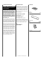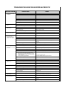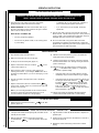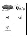
1
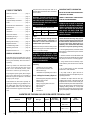
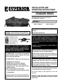
INSTALLATION AND
OPERATING INSTRUCTIONS
STANDARD SERIES
Unvented See-Through Gas Log Room Heaters
P/N 903588 REV. G 12/2007
MODELS
VFST-27VSN-2
VFST-27VSP-2
FOR USE ONLY WITH DECORATIVE TYPE UNVENTED ROOM
HEATERS.
INSTALLER: Leave this manual with the appliance.
CONSUMER: Retain this manual for future reference.
US
WARNING: IF THE INFORMATION IN THIS MANUAL
IS NOT FOLLOWED EXACTLY, A FIRE OR EXPLOSION MAY RESULT CAUSING PROPERTY DAMAGE,
PERSONAL INJURY OR LOSS OF LIFE.
FOR YOUR SAFETY: Do not store or use gasoline
or other flammable vapors or liquids in the vicinity
of this or any other appliance.
FOR YOUR SAFETY: What to do if you smell gas:
•
•
•
•
DO NOT light any appliance.
DO NOT touch any electrical switches.
DO NOT use any phone in your building.
Immediately call your gas supplier from a
neighbor’s phone.
Follow your gas suppliers instructions.
• If your gas supplier cannot be reached, call the
fire department.
Installation and service must be performed by a
qualified installer, service agency or the gas supplier.
DO NOT BUILD A WOOD FIRE.
WARNING: IMPROPER INSTALLATION, ADJUSTMENT, ALTERATION, SERVICE OR MAINTENANCE CAN CAUSE INJURY OR PROPERTY DAMAGE. REFER TO THIS MANUAL.
FOR ASSISTANCE OR ADDITIONAL INFORMATION CONSULT A QUALIFIED INSTALLER, SERVICE AGENCY OR THE
GAS SUPPLIER.
WARNING: DO NOT BURN WOOD OR OTHER MATERIAL IN
THESE APPLIANCES.
CAREFULLY REVIEW THE INSTRUCTIONS SUPPLIED WITH
THE DECORATIVE TYPE UNVENTED ROOM HEATER FOR
THE MINIMUM FIREPLACE SIZE REQUIREMENT.
DO NOT INSTALL THE APPLIANCE IN THIS FIREBOX, UNLESS THIS FIREBOX MEETS THE MINIMUM DIMENSIONS
REQUIRED FOR THE INSTALLATIONS.
This is an unvented gas-fired heater. It uses air
(oxygen) from the room in which it is installed.
Provisions for adequate combustion and ventilation air must be provided. Refer to Combustion
and Ventilation Air Section, Page 3.
Due to high temperatures, the appliance should be located out
of traffic and away from furniture or draperies.
Do not place clothing or other materials on or near this
appliance.
IMPORTANT: READ THESE INSTALLATION INSTRUCTIONS
CAREFULLY BEFORE INSTALLING OR TRYING TO OPERATE
THIS HEATER.
NOTE: DIAGRAMS & ILLUSTRATION NOT TO SCALE.
1
TABLE OF CONTENTS
General Information ......................... page 2
Inventory ......................................... page 2
Tools Required ................................ page 2
Important Safety Information .......... page 2
Codes .............................................. page 3
Combustion and Ventilation Air ....... page 3
Preinstallation .................................. page 4
Clearances ....................................... page 4
Installation ....................................... page 6
Gas Pressure Check ......................... page 6
The pilot can be relit only when fresh air is
available. Refer to the Combustion and Ventilation Air section.
IMPORTANT SAFETY INFORMATION
WARNING: THIS APPLIANCE IS FOR INSTALLATION IN A SOLID FUEL BURNING FIREPLACE WITH A WORKING FLUE
OR AN APPROVED VENTLESS FIREBOX
ENCLOSURE ONLY.
OWNER: PLEASE RETAIN THESE INSTRUCTION FOR FUTURE REFERENCE.
Minimum Fireplace (Firebox) Size
Height
Depth
Width
16"
18"
28" Front
Assembling the Logs ....................... page 7
Table 1
Flame Appearance ........................... page 7
Do not install these See-Through Unvented
Gas Log Room Heaters in a bedroom or a
bathroom as all units exceed maximum allowable BTU/hr input of 10,000.
Cleaning and Servicing .................... page 8
Replacement Parts .......................... page 8
Troubleshooting Guide .................... page 9
Operating Instructions ..................... page 10
Replacement Parts List .................... page 12
GENERAL INFORMATION
These See-Through Unvented Gas Log Room
Heaters incorporate unitized ceramic fiber logs
which glow realistically when the heater is
operating.
These log heaters are either thermostatic
(T-stat) or manually controlled. The control
knob is set to the desired position, which
maintains a continuous gas burning rate.
A spark ignition system (piezo) allows the gas
pilot to be lit without the use of matches or
batteries and permits operation of the heater
during a power outage.
These heaters are fitted with a specially designed pilot utilizing an oxygen depletion sensor (ODS) which responds to the amount of
oxygen available in the room and shuts the
heater off before the oxygen level drops below
18%.
Check the inventory list to be sure that you have
all the necessary parts in usable condition. Also
check for concealed damage.
WARNING: FAILURE TO INSTALL THESE
LOGS EXACTLY AS DETAILED IN THIS
INSTRUCTION MANUAL MAY RESULT IN
SOOTING AND MAY RESULT IN VOIDING
PRODUCT WARRANTIES.
Inventory
Unvented gas log room heater
Bag of decorative volcanic rock
Ceramic fiber logs
Installation and Operating Instructions
Tools and Supplies Normally Required
External regulator (Propane models only)
Manual shut-off valve
Sediment trap
Piping complying with local codes
Pipe compound
Pipe wrench
Tee joint
Screwdriver
INSTALLER: PLEASE LEAVE THESE INSTRUCTIONS WITH THE OWNER.
WARNING: ANY CHANGE TO THIS ROOM
HEATER OR ITS CONTROLS CAN BE DANGEROUS. IMPROPER INSTALLATION OR
USE OF THIS HEATER CAN CAUSE SERIOUS INJURY OR DEATH FROM FIRE,
BURNS, EXPLOSION OR CARBON MONOXIDE POISONING.
Carbon Monoxide Poisoning: Early signs of
carbon monoxide poisoning are similar to the
flu with headaches, dizziness and/or nausea.
If you have these signs, obtain fresh air immediately. Have the Unvented Gas Heater
serviced as it may not be operating correctly.
• Due to high temperatures, the heater should
be located out of traffic and away from furniture
and draperies.
• Children and adults should be alerted to the
hazard of high surface temperature and should
stay away to avoid burns or clothing ignition.
• Young children should be carefully supervised when they are in the same room with the
heater.
• Do not place clothing or other flammable
material on or near the heater.
• Any safety screen or guard removed for
servicing the heater must be replaced prior to
operating the heater.
• Installation and repair should be done by a
qualified service person. The heater should be
inspected before use and at least annually by a
professional service person. More frequent cleaning may be required due to excessive lint from
carpeting, bedding material, etc. It is important
that control compartments, burners and circulating air passageways of the heater be kept clean.
UNVENTED SEE-THROUGH GAS LOG ROOM HEATER TECHNICAL CHART
BTU/HR
High
Gas Type
Ignition
VFST-27VSN
34,000
Natural
Piezo
5" w.c.
VFST-27VSP
34,000
Propane/LPG
Piezo
10" w.c.
Model No.
Regulator
Pres. Setting
Gas Inlet
Pressure
Valve
Operation
Max. 10.5" w.c.
Min. 6" w.c.
Max. 13" w.c.
Min. 11" w.c.
Manual (Millvolt)
Manual (Millvolt)
Note: Test gage connections are provided on the front of the gas control valve (identified A for the manifold side and E for inlet pressure).
2
NOTE: DIAGRAMS & ILLUSTRATION NOT TO SCALE.
• Allow the heater to cool before servicing.
Always shut off the gas to the heater while
performing service work.
Massachusetts And New York Requirements
• Do not install the heater in a bedroom or
bathroom.
These appliances are approved for installation
in the following USA locations listed in the
following:
• The installation must conform with local
codes or, in the absence of local codes with the
National Fuel Gas Code, ANSI Z223.1.
• The heater and its individual shut-off valve
must be disconnected from the gas supply
piping system while performing any tests of the
gas supply piping system at pressures in excess of 1/2 psig.
• The heater must be isolated from the gas
supply piping system by closing its individual
manual shut-off valve during any pressure testing of the gas supply piping system at test
pressures equal to or less than 1/2 psig.
• Keep heater area clear and free from combustible materials, gasoline and other flammable vapors and liquids.
• Do not use this heater if any part has been
under water. Immediately call a qualified service technician to inspect the room heater and
to replace any part of the control system and
any gas control which has been under water.
• Input ratings are shown in BTU per hour and
are for elevations up to 4,800 feet. Do not install
this heater at an elevation above 4,800 feet if the
gas supply has not been derated for that elevation. Consult your local gas supplier. (For operation at elevations above 4,800 feet, equipment ratings shall be reduced at the rate of 4
percent for each 1,000 feet above sea level
before selecting appropriately sized equipment.)
• Ensure that the heater is clean when operating. Excessive dust accumulation on the burner
and/or logs will increase the amount of carbon
monoxide formation and could lead to carbon
monoxide poisoning and/or death.
• DO NOT install this heater into a single (front)
opening fireplace. This heater is designed to be
used in see-through (multi-open) fireplaces only.
CODES
Adhere to all local codes or in their absence the
latest edition of The National Fuel Gas Code
ANSI Z223.1 or NFPA54 which can be obtained
from The American National Standards Institute, Inc. (1430 Broadway, New York, NY,
10018) or National Fire Protection Association,
Inc. (Batterymarch Park, Quincy, MA, 02269).
Massachusetts:
These fireplaces are approved for installation
in the US state of Massachusetts if the following additional requirements are met• Installation and repair must be done by a
plumber or gas fitter licensed in the Commonwealth of Massachusetts.
• The flexible gas line connector used shall not
exceed 36 inches (92 centimeters) in length.
• The individual manual shut-off must be a Thandle type valve.
• Vent-Free appliances may NOT be installed in
bedrooms or bathrooms.
• A working smoke detector must be installed
in the area where vent-free appliances are
installed.
Seller of unvented propane or natural gasfired supplemental room heaters shall provide to each purchaser a copy of 527 CMR 30
upon sale of the unit.
New York:
These fireplaces are approved for installation
in the US state of New York, but not in New
York city.
State or local codes may only allow operation of
this appliance (manual version only) in a vented
configuration. Check your state or local codes.
Superior Unvented Gas Log Room Heaters are
certified by OMNI to ANSI Z21.11.2 standard.
These gas log room heaters may be used as a
space heat source for a room in conjunction with
an approved unvented firebox. Additionally,
manually controlled units are design certified by
OMNI to ANSI 21.60 as a vented gas log set.
The National Fuel Gas Code defines a confined
space as a space whose volume is less than
50 ft 3 per 1,000 BTU/Hr (4.8 m3 per kw) of the
aggregate input rating of all appliances installed in that space and an unconfined space
as a space whose volume is not less than 50 ft 3
per 1,000 BTU/Hr (4.8 m3 per kw) of the aggregate input rating of all appliances installed in
that space. Rooms communicating directly with
the space in which the appliances are installed,
through openings not furnished with doors, are
considered a part of the unconfined space.
Unusually tight construction is defined as construction where:
a. wall and ceilings exposed to the outside
atmosphere have a continuous water vapor
retarder with a rating or one perm or less with
openings gasketed or sealed, and
b. weather stripping has been added on operable windows and doors, and
c. caulking or sealants are applied to areas such
as joints around window and door frames,
between sole plates and floors, between wallceiling joints, between wall panels, at penetrations for plumbing, electrical, and gas lines,
and at other openings.
Use the following equations to determine if you
have a confined or unconfined space.
1. Determine the volume of space — ft 3.
Length x Width x Height = _____ ft 3
(Include adjoining rooms with doorless passageways or ventilation grills between
rooms.)
Example: 24' (L) x 16' (W) x 8' (H) = 3072 ft 3
2. Divide the volume of space by 50 ft 3 to
determine the maximum BTU/Hr the space
can support.
______ (volume of space – ft 3)/ 50 ft 3 =
(Maximum BTU/Hr the space can support)
COMBUSTION AND VENTILATION AIR
These heaters shall not be installed in a confined space. The heater may be located in
unusually tight construction provided the
space is unconfined, or if confined, is provided with two permanent openings communicating directly with an additional room(s)
of sufficient volume so that the combined
volume of all connected spaces meets the
criteria for an unconfined space, (National
Fuel Gas Code ANSI Z223.1 (latest edition),
Section 5.3). Generally 50 ft 3 per 1,000 BTU
input of all operating appliances in the space.
NOTE: DIAGRAMS & ILLUSTRATION NOT TO SCALE.
Example: 3072 ft 3 / 50 ft 3 = 61.44
or 61,440 BTU/Hr the space can support.
3. Add the BTU/Hr of all the fuel burning appliances in the space.
Vent-Free heater
Gas appliance #1*
Gas appliance #2
_______ BTU/Hr
_______ BTU/Hr
+ _______ BTU/Hr
Total = _______
BTU/Hr
3
Example:
VFST heater
34,000
Gas appliance #1
35,000
(water heater)
Total = 69,000
BTU/Hr
BTU/Hr
BTU/Hr
* Do not include direct-vent gas appliances.
Direct-vent is sealed combustion and draws
combustion air from the outdoors.
PREINSTALLATION
Check Gas Type
WARNING: BEFORE INSTALLING IN A
SOLID FUEL BURNING FIREPLACE, THE
CHIMNEY FLUE AND FIREBOX MUST BE
CLEANED OF SOOT, CREOSOTE, ASHES
AND LOOSE PAINT BY A QUALIFIED
CHIMNEY CLEANER.
This heater can only be connected to the gas
type specified on the heater rating plate. This
heater can not be modified in the field for a
different gas type. If the gas supply differs, DO
NOT INSTALL the heater. Contact your dealer to
obtain the correct heater.
CLEARANCES
4. Compare the maximum BTU/Hr the space
can support with the actual amount of BTU/
Hr used.
_________ BTU/Hr
(max. the space can support)
_________ BTU/Hr
(actual amount of BTU/Hr used)
Example:
61,440
69,000
BTU/Hr
(max. the space can support)
BTU/Hr
(actual amount of BTU/Hr used)
The space in the previous example is a confined
space because the actual BTU/Hr used is more
than the maximum BTU/Hr the space can support. You must provide additional fresh air.
Your options are:
a. Rework equations adding the space of adjoining room(s). If the extra volume provides
an unconfined space, then remove door or
add ventilation grills between rooms. Refer
to National Fuel Gas Code, ANSI Z223.1
1992, Section 5.3.
b. Vent room directly to the outdoors. Refer to
National Fuel Gas Code, ANSI Z223.1 1992,
Section 5.3.
If the actual BTU/Hr used is less than the
maximum BTU/Hr the space can support, then
the space is an unconfined space. You will need
no additional fresh air ventilation for an unconfined space.
WARNING: IF THE AREA IN WHICH THE
HEATER MAY BE OPERATED IS SMALLER
THAN THAT DEFINED AS AN UNCONFINED SPACE, PROVIDE ADEQUATE
COMBUSTION AND VENTILATION AIR BY
ONE OF THE METHODS DESCRIBED IN
THE NATIONAL FUEL GAS CODE, ANSI
Z223.1 1992, SECTION 5.3 OR APPLICABLE LOCAL CODES.
4
Note: Illustrations shown in this manual reflect
“typical” installations with nominal dimensions
and are for reference only. Actual installations
may vary due to individual design preferences.
However, always maintain minimum clearances
to combustible materials and do not violate any
specific installation requirements. Refer to Figures 1 through 7 for clearances.
Note: The following steps represent the normal
sequence of installation. Each installation is
unique, however, and might require a different
sequence.
When local codes require the damper to be fixed
open, a damper stop must be installed to prevent
full closure of the fireplace damper and provide
a minimum 29 square inch flue opening at all
times. Refer to accessories for damper clamp.
If damper clamp is not available, the damper
may be fixed open in the following manner.
Drill a hole in the end of the damper. Screw in
a bolt of sufficient size and adjust to provide the
minimum 29 square inches of flue opening.
WARNING: DO NOT INSTALL THIS GAS
HEATER:
• IN SLEEPING QUARTERS, BATHROOMS, A MOBILE HOME, OR A RECREATIONAL VEHICLE.
• WHERE CURTAINS, FURNITURE,
CLOTHING OR OTHER FLAMMABLE OBJECTS ARE LESS THAN 42" FROM THE
FRONT OF THE GAS HEATER.
• IN HIGH TRAFFIC AREAS.
• IN WINDY OR DRAFTY AREAS.
Ensure the minimum clearances shown in
Figures 1 through 7 are maintained. Left and
right clearances are determined when facing
the front of the heater.
Follow these instructions carefully to ensure
safe installation. Failure to follow these requirements may create a fire hazard.
Step 1. Sidewall Clearances: The sides of the
fireplace opening must be at least 16" from any
combustible side wall (Figure 1 ).
CAUTION: HEATERS CREATE WARM AIR CURRENTS. THESE CURRENTS MOVE HEAT TO
WALL SURFACES NEXT TO HEATER. INSTALLING HEATER NEXT TO VINYL OR CLOTH WALL
COVERINGS OR OPERATING HEATER WHERE
IMPURITIES IN THE AIR (SUCH AS TOBACCO
SMOKE) EXISTS, MAY DISCOLOR WALLS.
42"
Min.
16"
Min.
Step 1. Turn off gas supply to the fireplace or
firebox.
Step 2. Install and secure heater in fireplace or
firebox.
Step 3. Connect gas line.
Step 4. Assemble logs and test flame.
Step 5. Sprinkle volcanic rock over base plate
in front of and below the main burner.
NOTE: DIAGRAMS & ILLUSTRATION NOT TO SCALE.
Figure 1
Step 2. Ceiling Clearance: The ceiling must be
at least 42" from the top of the heater opening
(Figure 1 ).
Noncombustible Material Requirements with No Mantel Installed
(A) Noncombustible Material Measurement
Requirements for Safe Installation
12" or more
Adjustable canopy not required.
8" minimum to 12"
Install adjustable canopy, P/N 053751 or
P/N 053752 (Figure 3 ).
Less than 8"
Example: The bottom of the mantel may project
from the wall a maximum of 2-1/2" at a minimum of 28" above the opening. The top shelf of
the mantel may project a maximum of 6" at a
minimum of 34-1/2" above the opening.
Ceiling
10"
8"
6"
Extend noncombustible material to at least
8" and install adjustable canopy (Figure 3 ).
or
Extend noncombustible material to a height
of at least 12".
42"
2-1/2"
38-5/8"
34-1/2"
28"
Table 2
Heat Resistant
Material
12"
Noncombustible Material Heights and Mantel Location
Requirements for Safe Installation
with Wood Mantel, Shelf or
Other Combustible Projection
Noncombustible Material Measurement
12" or more
Adjustable canopy not required. Observe profiles shown in Figure 4.
8" minimum to 12"
Install adjustable canopy and observe profiles shown in Figure 5.
or
Extend heat resistant material to at least 12"
and observe profiles shown in Figure 4.
Top Of Firebox Opening
(Both Sides Of Opening)
Figure 4
Example: The bottom of the mantel may project
from the wall a maximum of 2-1/2 at a minimum of 8" above the opening. The top shelf of
the mantel may project a maximum of 6" at a
minimum of 14-1/2" above the opening.
12"
10"
8"
6"
Table 3
Step 3. Noncombustible materials (minimum
requirements): To install the room heater without wood mantels, shelves or other combustible projections directly above the opening of
the fireplace (firebox) refer to Figure 2 and
Table 2. Note that at least 8" of noncombustible
material must be installed above the heaters
described in this manual.
2-1/2"
8" or More of
Noncombustible
Material
18-5/8"
Heat Resistant
Material
Hood (Canopy)
Top Of Firebox Opening
(Both Sides Of Opening)
Heater in Fireplace
or Firebox
Noncombustible
Material
Figure 3
Heater in Fireplace
or Firebox
8"
Min.
14-1/2"
Adjustable
Canopy
Noncombustible materials, such as slate and
marble, must be at least ¹⁄₂" thick.
A
26"
22-1/2"
Step 4. Wood mantel, shelf or combustible
projection requirements: To install a wood
mantel, shelf or other combustible projection
directly above the fireplace (firebox), refer to
Table 3 and to Figures 4 and 5 for installation
profiles.
Figure 5
Step 5. Floor clearance: If combustible flooring materials, such as carpeting or asphalt tile,
are to be located within 14" of the fireplace or
nirebox opening, the room heater base must be
at least 5" above the combustible flooring material (Figure 6 ).
Combustible
Material
Combustible
Material
If your mantel profile is unsafe, you may either:
5" Min.
• Raise the mantel to an acceptable height, or
Figure 2
• Remove the mantel.
NOTE: DIAGRAMS & ILLUSTRATION NOT TO SCALE.
Figure 6
5
The room heater base may be lower than 5"
above the combustible flooring materials if
the combustible flooring materials are more
than 14" from the fireplace or firebox opening
(Figure 7 ).
Combustible
Material
Can be less
than 5"
14" Min.
(Both Sides Of Opening)
Figure 7
A qualified gas appliance installer must install
this heater.
Check gas type: The gas supply must be the
same as stated on the heater’s rating plate. If
the gas supply is different, DO NOT INSTALL
the heater. Contact your dealer for the correct
model.
Step 1. Placement of the Heater – Center the
heater in the fireplace or firebox. Make certain
the grate front feet sit inside the front edge of
the fireplace or firebox clear of any operating
screens.
Step 2. Connecting Gas Line – A qualified gas
appliance installer must connect the gas room
heater to the gas supply.
INSTALLATION
Consult all local codes.
WARNING: DO NOT ALLOW FANS TO
BLOW DIRECTLY INTO THE FIREPLACE.
AVOID ANY DRAFTS THAT ALTER
BURNER FLAME PATTERNS.
WARNING: DO NOT USE A BLOWER INSERT, HEAT EXCHANGER INSERT OR
OTHER ACCESSORY NOT APPROVED
FOR USE WITH THIS HEATER.
This appliance must not be operated without a
fireplace screen installed. Fireplace screens
must not impair the free flow of combustion air
to the appliance.
Do not burn solid fuels in any fireplace equipped
with this listed unvented gas room heater.
When rigid pipe is used, an ANSI approved
manual shut-off valve and union must be installed upstream of the heater within the fireplace cavity.
Ensure that a sediment trap is installed in the
existing gas line, if not, install a sediment trap
upstream of the heater to prevent moisture and
contaminants from passing through trap to the
heater controls and burners. Failure to do so
could prevent the heater from operating reliably.
Installed decorative glass door enclosures must
be fully opened when operating this listed unvented gas room heater.
An external regulator must be used on all propane (L.P.G.) heaters to reduce the supply tank
pressure to 13" w.c. (maximum). Any copper
tubing used to supply propane (L.P.G.) from
the tank must be internally tinned.
Any outside air ducts and/or ash dumps that are
part of the original solid fuel burning fireplace
system must be fully closed and sealed at the
time of installation of this listed unvented gas
room heater.
IMPORTANT: HOLD HEATER VALVE SECURELY TO PREVENT MOVEMENT WHEN
CONNECTING TO INLET GAS LINE
WARNING: SPECIAL CARE IS REQUIRED
IF YOU ARE INSTALLING THE UNIT INTO
A SUNKEN FIREPLACE. YOU MUST RAISE
THE FIREPLACE FLOOR TO ALLOW ACCESS TO GAS LOG CONTROLS. THIS WILL
INSURE ADEQUATE AIR FLOW AND
GUARD AGAINST SOOTING. RAISE THE
FIREPLACE FLOOR USING NONCOMBUSTIBLE MATERIALS.
6
Route gas line using techniques and materials
prescribed by local and/or national codes. Only
use gas line of ¹⁄₂" or greater diameter to allow
full gas volume to the gas fireplace. Undue
pressure loss will occur if the pipe is too small.
Checking Gas Connections
Secure all joints tightly using appropriate
tools and sealing compounds (ensure propane resistant compounds are used in
propane applications).
Turn on gas supply and test for gas leaks,
using a gas leak test solution (also referred to
as bubble leak solution).
Note: Using a soapy water solution (50% dish
soap, 50% water) is an effective leak test
solution but it is not recommended, because
the soap residue that is left on the pipes/
fittings can result in corrosion over time. Never
use an open flame to check for leaks.
A. Light the appliance (refer to safety and
lighting instructions on pages 12 and 14.
B. Brush all joints and connections with the
gas leak test solution to check for leaks. If
bubbles are formed, or gas odor is detected,
turn the gas control knob to the “OFF” position. Either tighten or refasten the leaking
connection and retest as described above.
C. When the gas lines are tested and leak free,
be sure to rinse off the leak testing solution.
D. When the gas lines are tested and leak free,
observe the individual tongues of flame on the
burner. Make sure all ports are open and
producing flame evenly across the burner. If
any ports are blocked, or partially blocked,
clean out the ports.
Gas Pressure Check
Check inlet gas pressure to ensure it is within
the limits specified in the chart on page 2. Test
gage connections are provided on the front of
the gas control valve (identified A for the manifold and E for inlet pressure.
WARNING: CONNECTING DIRECTLY TO
AN UNREGULATED PROPANE (L.P.G.)
TANK MAY CAUSE AN EXPLOSION.
The heater gas inlet connection is ³⁄₈" NPT at
the regulator, made on the right side facing the
heater. If a left side gas line is required, the gas
line may be led under the rear of the heater to
end at the right hand side for connection to the
inlet. However, this method is not recommended. For an easier connection to the
Unvented Gas Log Room Heaters, connection
fittings have been supplied with the firebox.
Cut and flare tubing to fit.
NOTE: DIAGRAMS & ILLUSTRATION NOT TO SCALE.
Gas Valve (Pressure
Test Points Located
On Front)
Figure 8
The pressure should be checked with the gas
heater burning and the control set to high (3).
Replace the test point plugs after pressure
measurement ensuring no gas leaks.
Step 3. Assembling the Logs
WARNING: DO NOT ADD EXTRA LOGS OR
ORNAMENTS SUCH AS PINE CONES, VERMICULITE OR ROCK WOOL. USING THESE
ADDED ITEMS CAN CAUSE SOOTING.
WARNING: DO NOT PLACE ANY LAVA
ROCK ON LOGS OR BURNERS. THIS MAY
CAUSE SOOTING. ONLY PLACE LAVA
ROCK ON FLOOR OF FIREPLACE.
The heater includes a unitized set of eight
ceramic fiber logs. The heater and logs are
assembled as shown in Figure 9. Handle these
logs with great care. The logs can be easily
damaged, but when handled properly they can
provide years of performance and enjoyment.
An incorrect pilot flame pattern is shown in
Figure 11. This pilot flame will cause the
thermocouple to cool. When the thermocouple
cools, the log set will shut off. If pilot flame
pattern is incorrect, or if log set shuts off,
contact your service representative.
WARNING: FAILURE TO POSITION THE
PARTS IN ACCORDANCE WITH THESE
DIAGRAMS OR FAILURE TO USE ONLY
PARTS SPECIFICALLY APPROVED WITH
THIS HEATER MAY RESULT IN PROPERTY DAMAGE OR PERSONAL INJURY.
Periodically check the positioning of all logs.
Flame Appearance
REFER TO THE OPERATING INSTRUCTIONS
LOCATED AT THE BACK OF THIS MANUAL
BEFORE LIGHTING THE HEATER TO OBSERVE
THE FLAMES.
Flames from the pilot, front and rear burner
should be visually checked as soon as the
heater is installed. In addition a periodic visual
check of the flames should be made. The pilot
flame should always be present when the heater
is in operation (Figure 10 ).
Figure 11
In normal operation, at full rate, after 15 minutes the following flame appearance should be
observed:
Burner Flame Characteristics – The flames
should be yellow. The flames should extend
about 3 – 4" above the logs for natural gas and
2 – 3" above for propane (L.P.G.) gas (Figure
12 ).
WARNING: NO ADJUSTMENTS ARE TO
BE MADE TO THE ODS PILOT SYSTEM.
TAMPERING WITH THIS SYSTEM CAN
BE EXTREMELY HAZARDOUS.
Note: Propane Model Shown
Figure 12
PILOT
CUT OUT
Figure 10
Figure 9
NOTE: DIAGRAMS & ILLUSTRATION NOT TO SCALE.
7
CLEANAING AND SERVICING
REPLACEMENT PARTS
WARNING: TURN OFF THE UNVENTED
GAS ROOM HEATER AND ALLOW TO COOL
BEFORE CLEANING.
An exploded view of the room heater with
numbered parts and a parts list can be found on
page 16. All parts should be ordered through
your Lennox distributor or dealer. Parts will be
shipped at prevailing prices at time of order.
CAUTION: YOU MUST KEEP CONTROL AREAS, BURNERS AND CIRCULATING AIR PASSAGEWAYS OF FIREPLACE CLEAN. INSPECT
THESE AREAS OF FIREPLACE BEFORE EACH
USE. HAVE FIREPLACE AND CHIMNEY (IF
APPLICABLE) INSPECTED YEARLY BY A
QUALIFIED SERVICE PERSON. FIREPLACE
MAY NEED MORE FREQUENT CLEANING DUE
TO EXCESSIVE LINT FORM CARPETING, BEDDING MATERIAL, ETC.
Only limited cleaning will be required under the
normal use of the heater. Dust the front grate, the
top of the piezo cover and the control knob
occasionally. Do not use cleaning fluids to clean
the logs or any other part of the room heater.
Remove the logs, gently handling at each end.
Use a vacuum cleaner to remove loose particles
from the base and from around the burners.
Gloves are recommended to prevent the fibers
from pricking your skin. If the skin is pricked,
wash gently with soap and water. Replace the
logs as detailed in Step 3 Assembling the Logs.
When ordering repair parts, always give the
following information:
Decorative
Volcanic Stone
VFVS
1. The model number of the heater.
2. The serial number of the heater.
3. The part number.
4. The description of the part.
5. The quantity required.
6. The installation date of the heater.
If you encounter any problems or have any
questions concerning the installation of this
heater, please contact your distributor. For the
name of your nearest distributor contact:
Adjustable Canopy
Brass
Black
AC - SPB
AC - BLK
LHP
1110 West Taft Avenue
Orange, CA 92865
If, after a period of use, the flames start to
exhibit unusual shapes and behavior, or the
burners fail to ignite smoothly, then the burner
holes may require some cleaning. If this happens, it is preferable to contact your nearest
dealer to get the appliance serviced.
8
ACCESSORIES
Damper Clamp
NOTE: DIAGRAMS & ILLUSTRATION NOT TO SCALE.
DCK
TROUBLESHOOTING GUIDE FOR UNVENTED GAS PRODUCTS
OBSERVED PROBLEM
POSSIBLE CAUSE
REMEDY
A. Igniter electrode positioned wrong.
Replace igniter.
B. Igniter electrode broken.
Replace igniter.
C. Igniter electrode not connected to igniter cable.
Reconnect igniter cable.
D. Igniter cable pinched or wet.
Free igniter cable if pinched by any metal or tubing. Keep igniter cable dry.
E. Piezo igniter nut is loose.
Tighten nut.
F. Broken igniter cable.
Replace igniter cable.
G. Bad piezo igniter.
Replace piezo igniter.
A. Heater burning vapors from paint, hair spray, glues, etc.
Ventilate room. Stop using odor-causing products while fireplace is running.
B. Gas leak. See Warning statement on the front page.
Locate and correct all leaks.
A. Not enough fresh air is available.
Open window and/or door for ventilation.
B. Low line pressure.
Contact local gas company.
C. ODS/pilot is partially clogged.
Clean ODS/pilot.
A. Gas leak. See Warning statement on the front page.
Locate and correct all leaks (see Checking Gas Connections, page 7).
B. Control valve defective.
Replace control valve.
A. Gas supply turned off or manual shut-off valve closed.
Turn on gas supply or open manual shut-off valve.
B. Control knob not in “PILOT” position.
Turn control knob to pilot position.
C. Control knob not pressed in while in “PILOT” position.
Press in control knob while in pilot position.
D. Air in gas lines when installed.
Continue holding down control knob. Repeat igniting operation until air is
removed.
E. ODS/pilot is clogged.
Replace ODS/pilot assembly or get it serviced.
F. Gas regulator setting is not correct.
Replace gas regulator.
A. Control knob not fully pressed in.
Press in control knob fully.
B. Control knob not pressed in long enough.
After ODS/pilot lights, keep control knob pressed in 30 seconds.
C. Manual shut-off valve not fully open.
Fully open manual shut-off valve.
D. Thermocouple connection loose at control valve.
Hand tighten until snug, then tighten ¹⁄₄ turn more.
E. Pilot flame not touching thermocouple, which allows
thermocouple to cool, causing pilot flame to go out. This
problem could be caused by one or both of the following:
1). Low gas pressure
2). Dirty or partially clogged ODS/pilot
1). Contact local gas company.
2). Replace ODS/pilot assembly or get pilot serviced.
F. Thermocouple damaged.
Replace thermocouple.
G. Control valve damaged.
Replace control valve.
A. Burner orifice is clogged.
Clean burner or replace burner orifice.
B. Burner orifice diameter is too small.
Replace burner orifice.
C. Inlet gas pressure is too low.
Contact local gas company.
A. Manifold pressure is too low.
Contact local gas company.
B. Burner orifice is clogged.
Clean burner or replace burner orifice.
A. Burner orifice is clogged or damaged.
Clean burner or replace burner orifice.
B. Burner damaged.
Replace burner.
C. Gas regulator defective.
Replace gas regulator.
10. Slight smoke or odor during
initial operation.
A. Vapors from paint or curing process of logs.
Problem will stop after a few hours of operation. SFC recommends running the
heater with excess ventilation for the first few hours.
11. Heater produces a whistling
noise when burner is lit.
A. Turning control knob to “HI” position when burner is cold.
Turn control knob to “LO” position and let warm up for a minute.
B. Air in gas line.
Operate burner until air is removed from line. Have gas line checked by local gas
company.
1. When igniter button is
pressed, there is no spark
at ODS/pilot.
2. Heater produces unwanted
odors.
3. Heater shuts off in use
(ODS operates).
4. Gas odor even when control
knob is in “OFF” position.
5. When igniter button is
pressed, there is spark at
ODS/pilot, but no ignition.
6. ODS/pilot lights, but flame
goes out when control knob
is released.
7. Burner does not light after
ODS/pilot is lit.
8. Delayed ignition of burner.
9. Burner backfiring during
combustion.
C. Dirty or partially clogged burner orifice.
Clean burner or replace burner orifice.
NOTE: DIAGRAMS & ILLUSTRATION NOT TO SCALE.
9
OPERATING INSTRUCTIONS
FOR YOUR SAFETY READ BEFORE LIGHTING
WARNING: IF YOU DO NOT FOLLOW THESE INSTRUCTIONS EXACTLY, A FIRE OR EXPLOSION MAY
RESULT CAUSING PROPERTY DAMAGE, PERSONAL INJURY OR LOSS OF LIFE.
A. This heater has a pilot which must be lit by hand. When
lighting the pilot, follow these instructions exactly.
• Immediately call your gas supplier from a neighbor’s
phone. Follow the gas supplier’s instructions.
B. BEFORE OPERATING smell all around the heater area for gas.
Be sure to smell next to the floor because some gas is heavier
than air and will settle on the floor.
• If you cannot reach your gas supplier, call the fire
department.
C. Use only your hand to push in or turn the gas control knob.
Never use tools. If the knob will not push in or turn by hand, do
not try to repair it, call a qualified service technician. Forced or
attempted repair may result in a fire or explosion.
WHAT TO DO IF YOU SMELL GAS
• Do not try to light any appliance.
• Do not touch any electric switch; do not use any phone
in your building.
D. Do not use this heater if any part has been under water.
Immediately call a qualified service technician to inspect the
appliance and to replace any part of the control system and any
gas control which has been under water.
LIGHTING INSTRUCTIONS
8. With the control knob pressed in, push in and release the
piezo igniter button to light the pilot.
1. Stop! Read the safety information above.
2. Make sure manual shut-off valve is fully open.
9. Hold the control knob in for a further 10 seconds to prevent
the flame failure detector from shutting off the gas while the
probe is warming up.
3. Locate gas control knob and piezo (Figure 13 ).
4. Depress control knob in and turn clockwise
“OFF” position (Figure 14 ).
to the
5. Wait 5 minutes to clear out any gas. Then smell for gas,
including near the floor. If you smell gas, STOP! Follow “B” in
the safety information above. If you do not smell gas, go to the
next step.
6. The pilot is located on the right side in front of the burner
(Figure 15 ).
7. Depress control knob in and turn counterclockwise
to the “PILOT” position (Figure 16 ). Press the control knob all
the way in for 5 seconds.
Note: If you are running the heater for the first time it will be
necessary to press the control knob all the way in for 30
seconds to allow air to bleed out of the gas piping.
10. Release the control knob while turning counterclockwise
to the "ON" Position (Figure 17 ). Then adjust
"HI-LO" knob to prefered setting.
•
If the knob does not pop out when released, stop and
immediately call your service technician or gas supplier.
•
If the pilot will not stay lit after several tries, depress and
turn the gas control knob clockwise
to “OFF”
and wait 30 seconds. Depress and turn knob counterclockwise
to “ON” and press igniter button
again. If your pilot does not relight depress and turn
control knob clockwise
to “OFF” and call your
service technician or gas supplier.
11. Wait 30 seconds before readjusting the heater when the
control knob has been turned down to a lower setting.
TO TURN OFF GAS TO HEATER
1. Depress and turn control knob clockwise
position (Figure 18 ).
to the “OFF”
MANUAL MATCH LIGHTING PROCEDURE — EMERGENCY ONLY
10
1. If the pilot cannot be lit with the piezo igniter, the heater can be
manually lit with a match.
3. Light the match and hold the flame to the end of the pilot and
ignite the pilot.
2. With the right hand, depress and turn the control knob
counterclockwise
to the “ON” position. Hold in the
knob.
4. Continue to hold control knob for an additional 10 seconds to
insure pilot remains lit.
5. Release the control while turning control knob to desired
setting.
NOTE: DIAGRAMS & ILLUSTRATION NOT TO SCALE.
Pilot
Piezo Ignitor
Flame Adjustment
Knob
Control Knob Locations
Pilot Location
Figure 13
Figure 15
ON
PIL O T
it
ON
OFF
PIL O T
it
Gas Control
Knob
OFF
Note: Knob cannot be turned from “PILOT” to “OFF”
unless the knob is pushed in slightly. Do not force.
Turn Control Knob to “PILOT” Position
Turn Control Knob to “OFF” Position
Figure 14
OFF
it
ON
Figure 16
PIL O T
Turn Control Knob to “ON” Position
Figure 17
NOTE: DIAGRAMS & ILLUSTRATION NOT TO SCALE.
11
REPLACEMENT PARTS LIST
No.
12
Description
VFST-27VSN
Part No.
VFST-27VSP
Part No.
1.
Valve - Millivolt
903489
901917
2.
Pilot Assembly
901914
901915
3.
Piezo
111061
111061
4.
Piezo Wire
110361
110361
5.
Burner
112281
112281
Burner (Valve Side)
112291
112291
6.
Burner Orifice (2 Each)
110389
110384
7.
Burner Crossover Tube
110321
110321
8.
Crossover Tube Orifice
110387
110388
9.
Log Set
100110
100110
NOTE: DIAGRAMS & ILLUSTRATION NOT TO SCALE.
REPLACEMENT PARTS
9
1
7
8
4
3
2
5
6
NOTE: DIAGRAMS & ILLUSTRATION NOT TO SCALE.
13
14
NOTE:
THIS PAGE&INTENTIONALLY
LEFTTO
BLANK.
NOTE:
DIAGRAMS
ILLUSTRATION NOT
SCALE.
NOTE:
THIS PAGE&INTENTIONALLY
LEFTTO
BLANK.
NOTE:
DIAGRAMS
ILLUSTRATION NOT
SCALE.
15
The manufacturer reserves the right to make changes at any time, without notice, in design, materials, specifications, prices and also to discontinue colors, styles and products.
Consult your local distributor for fireplace code information.
LHP
Printed in U.S.A. © 1997 by Lennox Hearth Products
P/N 903588 REV. G 12/2007
1110 West Taft Avenue
Orange, CA 92865