1
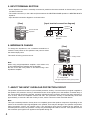
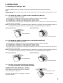
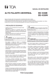
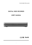
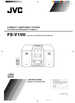
日本語の取扱説明書は本書の裏面をご覧ください。
OPERATING INSTRUCTIONS
SPEAKER SYSTEMS
HS-1200BT
HS-1200WT
HS-1500BT
HS-1500WT
TABLE OF CONTENTS
1. SAFETY PRECAUTIONS ........................... 2
8. INSTALLATION .......................................... 5
2. GENERAL DESCRIPTION ......................... 3
9. EQUALIZING BY THE
DIGITAL SIGNAL PROCESSOR ............... 7
3. FEATURES ................................................. 3
4. DIMENSIONAL DIAGRAM ......................... 3
5. INPUT TERMINAL SECTION ..................... 4
6. IMPEDANCE CHANGE .............................. 4
10. SPECIFICATIONS ...................................... 8
Accessories ................................................. 8
Optional products ........................................ 8
7. ABOUT THE INPUT OVERLOAD
PROTECTION CIRCUIT ............................. 4
Thank you for purchasing TOA's Speaker System.
Please carefully follow the instructions in this manual to ensure long, trouble-free use of your equipment.
1. SAFETY PRECAUTIONS
• Before installation or use, be sure to carefully read all the instructions in this section for correct and safe
operation.
• Be sure to follow all the precautionary instructions in this section, which contain important warnings and/or
cautions regarding safety.
• After reading, keep this manual handy for future reference.
Safety Symbol and Message Conventions
Safety symbols and messages described below are used in this manual to prevent bodily injury and property
damage which could result from mishandling. Before operating your product, read this manual first and
understand the safety symbols and messages so you are thoroughly aware of the potential safety hazards.
WARNING
Indicates a potentially hazardous situation which, if mishandled, could
result in death or serious personal injury.
When Installing the Unit
• Avoid installing or mounting the unit in unstable locations, such as on a rickety table or a slanted surface.
Doing so may result in the unit falling down and causing personal injury and/or property damage.
• Install the unit only in a location that can structurally support the weight of the unit and the mounting bracket.
Doing otherwise may result in the unit falling down and causing personal injury and/or property damage.
• Since the unit is designed for in-door use, do not install it outdoors. If installed outdoors, the aging of parts
causes the unit to fall off, resulting in personal injury. Also, when it gets wet with rain, there is a danger of
electric shock.
• Owing to the unit's size and weight, be sure that at least two persons are available to install the unit. Failure
to do so could result in personal injury.
• Do not use other methods than specified to mount the bracket. Extreme force is applied to the unit and the
unit could fall off, possibly resulting in personal injuries.
• Use screws that are appropriate for the ceiling's or wall's structure and composition. Failure to do so may
cause the unit to fall, resulting in personal injury.
• Ensure that all screws are securely tightened. If they are not tightened or firmly secured after installation, the
unit could fall down, possibly resulting in personal injury.
• Use the specified mounting bracket in combination. Doing otherwise may cause the unit or component to fall
off, resulting in personal injury.
• Do not mount the unit in locations exposed to constant vibration. The mounting bracket can be damaged by
excessive vibration, potentially causing the unit to fall, which could result in personal injury.
CAUTION
Indicates a potentially hazardous situation which, if mishandled, could
result in moderate or minor personal injury, and/or property damage.
When Installing the Unit
• When unpacking or installing the unit, be sure to handle it with two or more persons. Falling or dropping the
unit may cause personal injury.
• Avoid touching the unit's sharp metal edge to prevent injury.
• To avoid electric shocks, be sure to switch off the amplifier's power when connecting speakers.
2
CAUTION
Indicates a potentially hazardous situation which, if mishandled, could
result in moderate or minor personal injury, and/or property damage.
When the Unit is in Use
• Do not place heavy objects on the unit as this may cause it to fall or break which may result in personal
injury and/or property damage. In addition, the object itself may fall off and cause injury and/or damage.
• Make sure that the volume control is set to minimum position before power is switched on. Loud noise
produced at high volume when power is switched on can impair hearing.
• Do not operate the unit for an extended period of time with the sound distorting. This is an indication of a
malfunction, which in turn can cause heat to generate and result in a fire.
2. GENERAL DESCRIPTION
TOA’s HS-1200 series and HS-1500 series speakers are 2-way speaker systems made of resin, and feature a
large diameter woofer. They can be installed in many different applications with combined use of the supplied
handles and the optional mounting brackets.
3. FEATURES
•
•
•
•
•
•
•
Tweeter array realizes a 90° horizontal x 40° vertical directivity control at high frequencies
Compact and lightweight with its high frequency tweeter array arranged in front of the low frequency woofer
Built-in overload protection circuitry for the tweeters
Both permanent and temporary installations available
Either vertical or horizontal speaker installation available for the permanent installation
Easy to carry with a handy handle
Both high- and low-impedance applications available by a rotary switch
4. DIMENSIONAL DIAGRAM
[Front]
[Side]
[Rear]
Screw terminal
A
NEUTRIK NL4MP
Speakon
Rotary switch
B
C
[Bottom]
Model
HS-1200BT/1200WT
HS-1500BT/1500WT
Dimensions
A
448 (17.64)
560 (22.05)
B
320 (12.6)
400 (15.75)
C
361 (14.21)
451 (17.76)
Unit: mm (inches)
3
5. INPUT TERMINAL SECTION
• As the Speakon connector is internally connected in parallel to the screw terminal as shown below, you can
use either of the two.
• The usable connector (on the cable end) that matches the NEUTRIK NL4MP Speakon is NEUTRIK NL4FX
Speakon.
• Input terminal connection diagram is as shown below.
[Input terminal connection diagram]
[Rear]
Speaker
Speaker
Screw terminal
Speakon
Screw terminal
6. IMPEDANCE CHANGE
NEUTRIK NL4MP
Speakon
[Rear]
To change the impedance, use a standard screwdriver to
rotate the rotary switch on the speaker's rear panel to select
the desired input power.
This switch is factory-preset to 670 Ω.
Rotary switch
Note
When using a high-impedance amplifier, never select 8 Ω,
as this will damage the speaker and the amplifier.
Be sure to turn the rotary switch to 8 Ω when using a lowimpedance amplifier.
Rotary switch
The figure represents factory-preset position.
7. ABOUT THE INPUT OVERLOAD PROTECTION CIRCUIT
The speaker system has a built-in input overload protection circuitry. If an excessive input signal is applied to
the speaker, the protection circuitry is activated and cuts off the signal input to the tweeters. A sudden drop of
the sound volume level during speaker operation indicates that the protection circuitry has been activated. In
such a case, reduce the amplifier volume and wait. The protection circuitry is automatically reset after
approximately 10 seconds. After the circuitry is reset, set the volume at a lower level than before.
Note
This input overload protection circuitry does not completely protect the speaker component. Depending on the
nature of the excessive input signal applied to the speaker, there may be damage to the speaker components
before protection circuitry can operate. Also, if the excessive input signal is applied to the speaker for
extended periods of time, the protection circuitry may be damaged and will not recover. Take special care that
the excessive input signal is not applied to the speaker during use.
4
8. INSTALLATION
8.1. Installing to a Ceiling or Wall
Install the speaker system to a ceiling or wall using the optional mounting brackets shown below.
Note
Refer to the instruction manual enclosed with the HY-1200 series or HY-1500 series Mounting Bracket for its
mounting details.
8.1.1. HY-1200VB, HY-1200VW, HY-1500VB and HY-1500VW Mounting Brackets
(For vertical speaker mounting)
• These brackets are designed to mount HS series speakers to ceilings or walls vertically.
HY-1200VB and HY-1200VW: For the HS-1200 series speaker system
HY-1500VB and HY-1500VW: For the HS-1500 series speaker system
• They allow speaker’s vertical angle to be adjusted. (Ceiling: From 15° upward to 90° downward, Wall: From
15° upward to 60° downward)
Note: They also permit speaker’s horizontal angle to be adjusted in conjunction with the optional HY-C0801 or
HY-C0801W Ceiling Mount Bracket, or the HY-W0801 or HY-W0801W Wall Mount Bracket.
[Ceiling installation]
[Wall installation]
Mounting Bracket
Mounting Bracket
8.1.2. HY-1200HB, HY-1200HW, HY-1500HB and HY-1500HW Mounting Brackets
(For horizontal speaker mounting)
• These brackets are designed to mount HS series speakers to ceilings or walls horizontally.
HY-1200HB and HY-1200HW: For the HS-1200 series speaker system
HY-1500HB and HY-1500HW: For the HS-1500 series speaker system
• They allow speaker’s vertical angle to be adjusted. (Ceiling: From 0° horizontal to 90° downward, Wall: From
15° upward to 60° downward)
Note: They also permit speaker’s horizontal angle to be adjusted in conjunction with the optional HY-C0801 or
HY-C0801W Ceiling Mount Bracket, or the HY-W0801 or HY-W0801W Wall Mount Bracket.
[Ceiling installation]
[Wall installation]
Mounting Bracket
Mounting Bracket
8.1.3. HY-C0801 and HY-C0801W Ceiling Mount Brackets
(For ceiling installation, horizontal angle adjustable)
Installing the HS series speaker to a ceiling in
conjunction with the HY-1200 series or HY-1500
series Mounting Bracket permits the speaker's
horizontal angle to be adjusted.
The figure at right shows an example of vertical
speaker installation.
Ceiling Moun Bracket
Mounting Bracket
5
8.1.4. HY-W0801 and HY-W0801W Wall Mount Brackets
(For wall installation, horizontal angle adjustable)
Wall Mount Bracket
Installing the HS series speaker to a wall in
conjunction with the HY-1200 series or HY-1500
series Mounting Bracket permits the speaker's
horizontal angle to be adjusted.
Mounting Bracket
The figure at right shows an example of vertical
speaker installation.
8.1.5. Safety wire installation (For speaker fall prevention)
When mounting the speaker system to the ceiling or wall, install a safety wire as needed.
When installing the safety wire, be sure to follow the instructions below.
Failure to do so may cause the speaker to fall off, resulting in personal
injury.
Use a wire rope of 2 mm (0.08") or more in diameter. (The safety wire is not supplied.)
Tighten the safety wire to take up the slack. Otherwise, impact shock at speaker fall may cause the wireconnected parts or wire itself to break.
Install the safety wire to a place that can structurally support the full weight of load.
Screw a speaker suspension bolt (M8) into one of the screw holes on the speaker's bottom surface.
Then, connect the safety wire to the bolt.
WARNING
•
•
•
•
Installation position of an M8 bolt
M8 (Screw pitch: 1.25 mm, effective depth: 24 mm)
Note: Unified inch screws cannot be used.
Speaker's
bottom surface
Changing the orientation of
the front panel logo
Turn the logo mark while holding its edges
to change its orientation.
8.2. Mounting on the ST-33B Speaker Stand (optional)
Note
Refer to the instruction manual enclosed with the
Speaker Stand for its mounting details.
Step 1. Fix the bracket supplied with the speaker stand
to the speaker.
Speaker
Bracket
(supplied with the Stand)
Step 2. Spread the tripod legs of the stand to their full
extension.
Note
Spread the tripod legs until the stays extend
horizontally.
Step 3. Mount the speaker with the bracket fixed onto
the stand.
Bracket fixing screw
Plain washer for M8
(supplied with the Stand)
Speaker mounting screw M8
(supplied with the Stand)
Step 4. Determine the speaker direction, and tighten
the bracket fixing screw.
Step 5. Adjust the stand height.
6
ST-33B Speaker Stand
8.3. Using as a Floor Monitor
Notes
• When installing the speaker system on slippery floor,
put a non-slip mat under the speaker.
• Do not kick or stand on the speaker system, as this
will damage the speaker.
The figure shows the HS-1200 series.
8.4. Attaching the Supplied Rubber Feet
Attach the rubber feet in the case of speaker storage or
on-floor speaker installation.
Datum line
Note
The rubber foot has a direction (back and forth).
Align the datum line on the rubber foot with the positioning
mark (
) on the speaker unit as shown at right.
Rubber foot
(accessory)
Positioning mark
Screw M6 x 30 (accessory)
8.5. Attaching a Handle
The speaker system comes with a handy carrying handle.
Attach the handle on the speaker's top surface.
Screw M6 x 30
(accessory)
Handle fitting bracket
(accessory)
Handle
(accessory)
9. EQUALIZING BY THE DIGITAL SIGNAL PROCESSOR
The speaker system is capable of providing high-efficiency and wide range reproduction without using an
equalizer, however more clear and dynamic sound quality can be reproduced by using our digital signal
processor and performing its settings as shown in the tables below.
[For the HS-1200BT and HS-1200WT]
Filter
Frequency (Hz)
HPF (12 dB)
50
PEQ
520
PEQ
1600
PEQ
2300
PEQ
5000
PEQ
14000
Gain (dB)
-4.0
-2.0
-4.0
-2.0
+3.0
Q
1.432
1.414
5.764
5.764
1.011
1.204
[For the HS-1500BT and HS-1500WT]
Filter
Frequency (Hz)
HPF (12 dB)
50
PEQ
530
PEQ
1300
PEQ
2500
PEQ
4500
PEQ
14000
Gain (dB)
-3.5
-3.0
-3.0
-3.5
+1.5
Q
1.274
2.145
2.871
2.871
1.011
0.718
7
10. SPECIFICATIONS
Model No.
Enclosure
Rated Power
Rated impedance
Sensitivity
Frequency Response
Crossover Frequency
Directivity Angle
Speaker Component
Input Terminal
Enclosure
Finish
Punched net
Operating Temperature
Dimensions
Weight
HS-1200BT
HS-1200WT
HS-1500BT
HS-1500WT
Sealed type
Continuous pink noise: 100 W, Continuous program: 300 W
8Ω
100 V line: 170 Ω (60 W), 330 Ω (30 W), 670 Ω (15 W)
70 V line: 83 Ω (60 W), 170 Ω (30 W), 330 Ω (15 W), 670 Ω (7.5 W)
97 dB (1 W, 1m)
98 dB (1 W, 1m)
70 to 20,000 Hz
60 to 20,000 Hz
3 kHz
Horizontal: 90°, Vertical: 40°
Low frequency
Low frequency
30 cm (12") cone type
38 cm (15") cone type
High frequency
High frequency
Balanced dome tweeter x 6
balanced dome tweeter x 6
NEUTRIK NL4MP Speakon and M4 screw terminal (Barrier spacing: 9 mm)
Polypropylene,
Polypropylene,
Polypropylene,
Polypropylene,
black
white
black
white
Surface-treated
Surface-treated
Surface-treated
Surface-treated
steel plate, black
steel plate, white
steel plate, black
steel plate, white
–10°C to +50°C (14°F to 122°F)
361 (w) x 448 (h) x 320 (d) mm
451 (w) x 560 (h) x 400 (d) mm
(14.21" x 17.64" x 12.6")
(17.76" x 22.05" x 15.75")
10 kg (22.05 lb)
14 kg (30.86 lb)
Note: The design and specifications are subject to change without notice for improvement.
• Accessories
Handle ................................................................................................ 1
Handle fitting bracket .......................................................................... 2
Rubber foot ......................................................................................... 2
Screw M6 x 30 (Used for attaching a handle and rubber foot.) .......... 4
• Optional products
Mounting bracket (For vertical speaker mounting): HY-1200VB, HY-1200VW, HY-1500VB, HY-1500VW
Mounting bracket (For horizontal speaker mounting): HY-1200HB, HY-1200HW, HY-1500HB, HY-1500HW
Ceiling mount bracket: HY-C0801, HY-C0801W
Wall mount bracket:
HY-W0801, HY-W0801W
Speaker stand:
ST-33B
Traceability Information for Europe (EMC directive 2004/108/EC)
Manufacturer:
TOA Corporation
7-2-1, Minatojima Nakamachi, Chuo-ku, Kobe, Hyogo,
Japan
Authorized representative:
TOA Electronics Europe GmbH
Suederstrasse 282, 20537 Hamburg,
Germany
URL: http://www.toa.jp/
533-06-176-1A