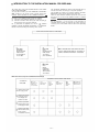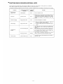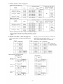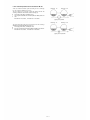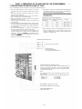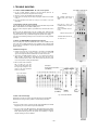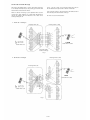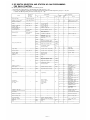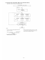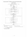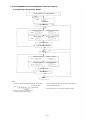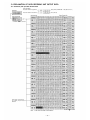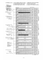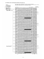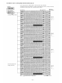
1
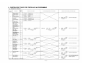
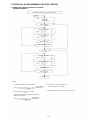
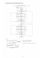
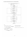
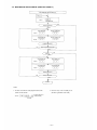
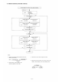
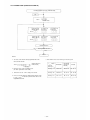
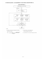
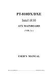
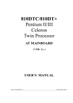
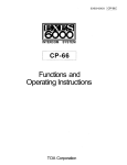
EXES-6000 CP-63
For
INTERCOM SYSTEM
TOA EXES-6OOO INTERCOM SYSTEM
Central Processing Unit for Tie-line System
CP-63
INSTALLATION HAND BOOK
TOA ELECTRIC CO., LTD.
KOBE, JAPAN
133-21-081-1
CONTENTS
Page
2
3
5
8
INTRODUCTION TO THE INSTALLATION MANUAL FOR EXES-6000
FUNCTIONS WHICH REQUIRE ADDITIONAL UNITS
TIE-LINE CONNECTION OF THE EXCHANGES
WIRING FOR TIE-LINE CONNECTION OF THE EXCHANGES
PART 1. OPERATING OF CP UNIT AND NO. 200 PROGRAMMING
1.
2.
3.
4.
5.
6.
7.
Precautions for Installation of CP-63
Initial CP 63 set up
Trouble Shooting
CP-63 DIP Switches for Function Selection
Dip Switch Selection and Station No. 200 Programming for Each Function
Function Code Table for Station No. 200 Programming
Station No. 200 Programming for Each Function
[Function Group A]
7-1
Executive Priority (Highest Priority)
7-2
Continuous Calling Tone
7-3
Stations Allowed Access to All Call
Stations Allowed Access to Conference
7-4
Automatic Access to Paging
7-5
7-6
Stations Allowed Access to One-shot Make Output
7-7
Stations Allowed Access to Make/Break Output
7-8
Stations Allowed Access to 8 Selectable or Decimal Output
7-9
Stations Allowed Access to 4 Decimal Digits Output
11
12
13
16
17
18
21
FUNCTION CODE
50
51
52
53
54
56
57
58
59
21
22
23
24
25
27
28
29
30
[Function Group B]
7-10 Secretary Transfer
7-11 Master/Sub Relationship
7-12 Group Hunting
60
61
62
31
32
33
[Function Group C]
7-13 Paging Zone
7-14 Group Blocking 1: Establishment of each Group
7-15 Calling Party Indication (Lamp Type)
70
71
72
34
35
36
[Function Group D]
7-16 Group Blocking 2: Allowing Calls among Groups
7-17 Group Blocking 3: Allowing Group Access to Paging
81
82
37
38
90
39
41
41
42
43
44
45
46
46
46
[Function Group E]
7-18 Programmable Station Numbering
8. Programming Data Table
Initial Programming
Function Table for the System
Function Table for Stations (1)
Function Table for Stations (2)
Function Table for Stations (3)
Paging Zone Table
Station Numbers Table for Calling Party Indication (Lamp Type)
Tables for Group Blocking (3 Tables)
PART 2. FUNCTION SELECTION FOR DATA TRANSMITTING AND RECEIVING UNITS
9. Setting of Channel Select Switch of Transmitting Unit (DT-E11)
and Word Select Switch of Receiving Unit (DR-B61)
10. DIP Switch Table for Data Transmitting and Receiving Units
11. System Diagram of Data Transmitting and Receiving Units
12. Explanation of Data Transmitting Unit Output Channels
13. Explanation of Data Receiving Unit Output Data
13-1
CH-0
IN-OUT Annunciation (500 Contacts)
13-2 CH-1
(1) One-Shot Make Output (50 Contacts)
(2) Make/Break Output (100 Contacts)
(3) 8-Selectable Make Output (9 Units)
(4) Decimal Output (9 Units)
(5) 4 Decimal Digits Output (9 Units)
(6) Pager Control Output (64 Contacts)
13-3 CH-2
Calling Party Indication (Lamp Type) (1)
13-4 CH-3
Calling Party Indication (Lamp Type) (2)
Appendix. Instructions for building the CP-63 in the EXES-5000
—1—
49
50
51
52
53
53
54
54
54
54
54
54
55
56
57
INTRODUCTION TO THE INSTALLATION MANUAL FOR EXES-6000
This manual forms part of the Installation Manual for TOA INTERCOM SYSTEM EXES-6000.
You may add the CP-63 to your TOA INTERCOM SYSTEM EXES6000, according to your specific needs, to obtain various other
functions. Correct operation of these additional functions is not
performed by simply connecting the additional equipments/devices.
Provision of such additional function requires the following:
(1) Connection of the additional equipment, as required.
(2) Selection of functions which satisfy your needs and setting up
these functions in the respective equipment.
For (1) Connections of Equipment, etc., refer to "
Installation
Handbook of Model EX-610/620 EXCHANGE" or
Operation
Manual of Data Transmitting and Receiving Units", etc.
This "Installation Handbook of CP-63" deals principally with (2)
Selection of functions and setting up of respective equipment.
This Handbook also explains the connection method for the EXES6000 Tie-line System using the CP-63 and the TI-62 units.
There are certain minimum installation requirements to be met even
through you may not need many additional functions or additonal
equipment, it is still necessary to read "2. Initial CP-63 Set Up
(Page 12)". When you may use only some of the additional functions or equipments, it is not necessary to read instructions on
unrequired functions. Make sure, however, that careful study of the
necessary parts of this booklet should be done before proceeding
further.
INSTALLATION HAND BOOK OF EXES-6000
EXES-6000
EX-610/620
INSTALLATION
HAND BOOK
OF EXCHANGE
133-21-100-9
EXES-6000
CP-63
INSTALLATION
HAND BOOK
133-21-081-1
(This Hand Book)
DATA TRANSMITTING AND RECEIVING UNIT
"DT-E11 OPERATION MANUAL" 133-05-094-1A
"DR-B61 OPERATION MANUAL" 133-05-095-0
EXES-6000
CP-63
INITIAL
CHECKING
SHEET FOR
THE SYSTEM
133-21-085-5
Manuals Necessary for Installation of Exchange
REQUIRED INSTALLATION HAND BOOK
SYSTEMS OF
EXES-6000
EX-610/620
INSTALLATION
HAND BOOK
OF EXCHANGE
CP-62
INSTALLATION
HAND BOOK
CP-62
INITIAL
CHECKING
SHEET
Normal Conversation
and Paging System
Normal Conversation
and Paging System
with Display and
Control Functions
Tie-line System with
Normal Conversation
and Paging Functions
Tie-line System with
Normal Conversation,
Paging, Display
and Control Functions
—2—
CP-63
INSTALLATION
HAND BOOK
CP-63
INITIAL
CHECKING
SHEET
DATA TRANSMITTING
AND RECEIVING UNIT
OPERATION MANUAL
FUNCTIONS WHICH REQUIRE ADDITIONAL UNITS
Those functions of the CP-63 which require either the addition of specific units or processing in existing units are as mentioned
below. Before installation and adjustment of equipment, make sure to check your system.
(For Data Transmitting and Receiving units, refer to Part 2. "Function Selection for Data Transmitting and Receiving units" Page 49.)
Function
Additional Equipment
Required
Unit Model
Number
Remarks
Talk- Back from
paging speaker
Talk-Back Unit
TK-12
Not yet available for sale.
Conference
Conference Unit
CL-62
Build this unit in all exchanges connected by tie-line. It
is not possible to originate a conference from a station
connected to the exchange without the CL unit but
possible to participate in the conference from that
station.
External PA Paging
Paging Interface Unit
PI -62
External PA Equipment is required.
Station Paging
Paging Interface Unit
PI-62
1. Wiring of "Station Paging Assignment" located at
the back of the frame of the Exchange.
2. Cutting of LM-62 jumper wire to split station paging
system.
Data Transmitting Unit
DT-E11
The number that can be mounted on the cabinet-mount
type exchange is one (1). Use the connection cable
YR-806.
When more than 2 pieces are mounted, we suggest you
use rack-mount type exchange. For connection between
the exchange and the DT-E11, use the YR-802, and
the YR-803 for extension of the DT-E11 .
Data Receiving Unit
DR-B61
Such devices as indicator, control unit etc. can be
made by using this unit and 24V DC power supply.
Tie-line Interface Unit
TI-62
Insert this unit into a slot intended for the PI unit No. 2
(Zone No. 8-15).
Indication and
Control
Tie-line System
—3—
Example of Exchange Mounted on Intercom Cabinet Rack
(For Tie-line System Including All-Call Paging and 7 Individual Zone Paging unit and one Data Transmitting unit)
Exchange EX-620 (for 128 stations)
Exchange EX-610 (for 64 stations)
Central Processing Unit CP-63
Power Supply Unit DS-620
Output Control Unit OC-62
Power Switch
Highway Control Unit HC-62
AC Fuse
Signal Generating and Distributing Unit SG-62
DC Fuse
Conference Link Unit CL-62 (In this location, DL-62 is also
mountable.)
Battery Fuse
Exchange Cabinet Rack CR-620
Duplex Link Unit DL-62
Exchange Frame FR-620
Line Modem Unit LM-62
Power Supply Unit DS-610
Paging Interface Unit PI-62 (In this location, LM-62 is also
mountable.) (Zone 0-7 with All-Call Paging)
Power Indication Lamp
Tie-line Interface Unit TI-62
Battery Power Indication Lamp
Perforated Panel PF-022G *
Buzzer Stop Switch
Data Transmitting Unit DT-E11 (In the standard system,
Perforated Panel PF-012G should come in this position.)*
Junction Cable YR-806 (Cable length: 1000mm) (YR-802 (Cable
length: 400mm) is not available.)
Exchange Cabinet Rack CR-610
Exchange Frame FR-610
Note.*
The Exchange Cabinet Rack CR-610 or CR-620 includes
Perforated Panels PF-012G and PF-022G.
—4—
TIE-LINE CONNECTION OF THE EXCHANGES
1. Function of the Central Processing Unit CP-63
Exchange "A"
To make communications between exchanges possible in the EXES6000 system, the CP-63 and the Tie-line Interface Unit TI-62 are
required in addition to the exchange EX-610 or the EX-620.
The TI-62 is the interface unit for transmitting and receiving audio
signals and dial data signals between the exchanges.
After receiving dial signals from the station, the CP-63 transmits the
dial data signals to the TI-62 and instructs it to make calls to the
other exchange. The CP-63 also receives the dial data signals from
the other exchange through the TI-62 and calls the station which is
instructed to call by the other exchange.
Overall functions of the system using the Tie-line function are
determined by programming made in the CP-63.
Exchange "B"
Dial
data
Audio
Signal
Call
Station
Station
2. Number of stations, paging zones and links
Maximum number of stations
Maximum
number
Maximum
of links
Composition
within
of exchange (s)
own exchange
Maximum
number of links
between tielined
Number
number
of
of
exchange
paging
exchanges
EX-610
EX-620
12
16
without
With Paging
Paging
(All call+7 zones)
zones
EX-610
EX-620 EX-610
EX-620
Without tie-lines
Single
Exchange
1
All call
+7zones
56
120
48
112
1
All call
+7zones
56
120
48
112
2
All call
+14zones
112
240
96
224
1
All call
+7zones
56
120
48
112
3
All call
+21zones
168
360
144
336
(EX-1)
2 exchanges
Exchange
"A"
8 links
(EX-2A)
Exchange
"B"
12
*1
16
8
*1
(EX-2B)
3 exchanges
(EX-3A)
Exchange
"A"
4 links
4 links
12
*1
Exchange
"C"
(EX-3C)
4 links
16
*1
4 between each
tielined link
Exchange
"B"
(EX-3B)
*1 The links within own exchange as well as the tie-line links are used in each
tie-line communication.
*2 All call paging is provided to all the paging zones of all the exchanges connected by tie-line.
—5—
3. Numbering schedule for stations and paging zones
A. With personal number (Standard)
Numbering for stations
Type of
Model
exchange
With
paging
Without Paging
Numbering for paging zones
7 zones
per
exchange
Paging zone per exchange
All call
Zone
EX-610
Single Exchange (EX-1)
Exchange "A" (EX-2A/3A)
EX-620
EX-610
Exchange "B" (EX-2B/3B)
EX-620
EX-610
Exchange "C" (EX-3C)
EX-620
B. Without personal number
Numbering for paging zones
Numbering for stations
Type of
Model
exchange
Single Exchange (EX-1)
Exchange "A" (EX-2A/3A)
With
paging
Without paging
7 zones
per
exchange
Paging zone per exchange
Zone
All call
EX-610
EX-620
EX-610
Exchange "B" (EX-2B/3B)
EX-620
EX-610
Exchange "C" (EX-3C)
EX-620
Zone No. 16 through 22 and No. 31 through 37 are employed for Paging
Numbering Schedule of 45 zones with 3 exchanges established in the system
using the exchanges EX-610 and/or EX-620 and EX-630 (256 stations) connected
by tie-line.
4. Reduction of the number of stations and paging zones
which results from the use of the Tie-line Interface Unit
TI-62.
1. Mounting one (1) piece of the TI-62 decreases the number of the
LM-62 (the 7th or the 15th LM-62) by one (1).
2. Unless the PI-62 is used, the system can have up to 8 more stations by placing the LM-62 in the 8th or the 16th position.
<EX-620>
<EX-610 >
LM
Station No.
LM
Station No.
LM
Station No.
1
200-207
1
200-207
9
264-271
2
208-215
2
208-215
10
272-279
3
216-223
3
216-223
11
280-287
4
224-231
4
224-231
12
288-295
5
232-239
5
232-239
13
296-303
6
240-247
6
240-247
14
304-311
7
248-255
7
248-255
15
312-319
8
256-263
8
256-263
16
320-327
PI
5. Block diagram for tielined exchanges.
<EX-610 Tie-line>
<EX-620 Tie-line>
Exchange "A"
(EX-2A/3A)
Exchange "B"
(EX-2B/3B)
Exchange "C"
(EX-3C)
— 6—
Note.
LM: Line Modem Unit
PI : Paging Interface Unit
Tl : Tie-line Interface Unit
PI
6. The relationship between the PI unit and the LM unit
Exchange "A"
<The case where the tie-line system consisting of 2 or 3 exchanges
has an exchange without the PI unit>
The case where it is necessary to make the paging call from the
exchange without the PI unit to the other exchange (s).
Set "Paging" DIP switch (SW-B-4) to ON.
You may not substitute the LM unit (LM8 or LM16) for the PI
unit.
EX-610: Max. 48 stations, EX-620: Max. 112 stations
Exchange "B"
paging call is possible
Exchange "A"
Exchange "B"
The case where the paging call is unnecessary from the exchange
without the PI unit to the other exchange (s).
Set "Paging" DIP switch (SW-B-4) to OFF.
You may substitute the LM unit (LM8 or LM16) for the PI unit.
EX-610: Max. 56 stations, EX-620: Max. 120 stations
paging call is impossible
—7—
WIRING FOR TIE-LINE CONNECTION OF THE EXCHANGES
Each exchange can be connected by means of a cable with a diameter of 0.65mm (25.6 mils.) for a distance of up to
2km (5600 ft).
Regarding the tieline links which are not used, turn off the DIP switch of each unused tieline link inside the Tie-line
Unit TI-62.
Connect "T" line (2 wires) of the 4 wires of each link to "R" line (2 wires) of the other exchange.
The 2 wires of the "T" line and "R" line have no polarity.
If the BX-610/620 is used, its terminals No. 1 and 2 are for the "R" line and No. 3 and 4 are for the "T" line.
Exchange "A"
Exchange "B"
1. Wiring for tie-line connection of 2 exchanges
Exchange "A"
EX-2A
Note 1.
Exchange "B"
EX-2B
Any combination of tie-line links between exchanges "A" and "B" is possible. But, in consideration of possible increase in the number of exchanges to be connected from 2 to 3 in the
future, we suggest you connect
(link No. 0, 1, 2, 3) of exchange "A" to
(link No. 4, 5,
6, 7) of exchange "B".
2. Wiring for tie-line connection of 3 exchanges
Exchange "A"
EX-3A
Exchange "C"
EX-3C
Note 2.
Be sure to connect
Connection of
to
Exchange "B"
EX-3B
(link No. 0, 1, 2,3) to
(link No. 4, 5, 6, 7) between the exchanges.
to
will lead to failure of proper operation of the system.
or
3. DIP Switch selection
DIP Switch
1. Switching arrangements of DIP switches
(E-1, E-2, E-3) in the CP-63 make each
exchange to be of "EX-1" or "EX-2A" or
"EX-2B" or "EX-3A" or "EX-3B" or "EX3C" type.
2. In the event of the tieline link not to be
used, turn off its corresponding DIP switch
on the TI-62 unit.
TI-62 P.C.B.
LINK No.
—8—
4. The Example of connection of EX-620 exchange
YR-801 must be connected to J15 for EX-620 exchange (for 128 stations), or to J7
for EX-610 exchange (for 64 station)
EX-620
BX-620
EX-610
BX-610
J15
T1
J7
T1
"Exchange A"
EX-620
"Exchange B"
EX-620
Terminal board
BX-620
YR-810
for stations
Terminal board
BX-620
YR-810
for stations
YR-801
for Tie-line
YR-801
for Tie-line
The cables between the exchanges
(4 wires x 8 links)
"Exchange B"
BX-620 T1
"Exchange A"
BX-620 T1
—9—
5. The Example of connection of EX-620 exchange
YR-810 must be connected to J15 for EX-620 exchange (for 128 stations), or to J7
for EX-610 exchange (for 64 station)
"Exchange A"
EX-620
"Exchange C"
EX-620
"Exchange B"
EX-620
YR-810
for stations
YR-801 for Tie-line
Terminal board
BX-620
Terminal Board
BX-620
Terminal board
BX-620
YR-810
for stations
YR-810
for stations
YR-801 for Tie-line
YR-801 for Tie-line
The cables between the exchanges (4 wires × 4 links)
The cables between the exchanges (4 wires x 4 links)
The cables between the exchanges (4 wires x 4 links)
"Exchange A"
BX-620 T1
"Exchange B"
BX-620 T1
— 10 —
"Exchange C"
BX-620 T1
PART 1. OPERATING OF CP UNIT AND NO. 200 PROGRAMMING
1. PRECAUTIONS FOR INSTALLATION OF CP-63
Please read following instructions carefully to ensure proper operation of the CP-63
1. Be careful about damage by static electricity as the CP-63
incorporates CMOS IC's. Do not touch components and connectors.
2. Turn off the AC power switch when you take out or insert the
CP-63 unit, or any other unit.
3. Always insert the CP-63 unit into the "CP" slot. Otherwise,
there is a danger that the unit will be damaged.
4. Make sure mini-jumper for battery back-up is always placed in
ON position each time it is used.
5. Incorrect setting of function select switches may lead to incorrect performance.
6. Even if you do not need programming functions, be sure to carry
out initial programming and registration at station No.200 when
you install the new unit. Otherwise, some other functions may
not work properly.
7. The Ni-Cd battery GB50-3FA1 is capable of saving important
memory registration data even at times of power failure.
To keep the battery fully charged, do not cut the power off for
long hours during the first 8 days after new installation. The
CP-63 unit is capable of maintaining the programmed data for
the period of 4 weeks after fully charged even in the event of
long hours of power failure.
(About 4 weeks (25°C), About 8 days (40°C)
8. We suggest you replace the soldered button battery GB50-3FA1
(115-42-031-9) with the new one according to the following list
that shows an expected life span of the battery.
Be sure to make the station No.200 programming after replacement of the battery.
Expected Life Span of small Ni-Cd Battery
Ambient temperature
of exchange
Ambient temperature
of battery
0°C
10°C
About 5 years
25° C
35° C
About 4 years
40° C
50° C
About 2 years
Life span
9. When shipping the CP-63 unit independently, place the minijumper for battery back-up in "OFF" position. Cover the CP
back with cardboard, wrap connector section in aluminium foil
and put it in a conductive bag.
FUNCTION SELECT SWITCHES
SW-E (1 ~ 6)
SW-D (1 ~ 6)
SW-C (1 ~ 6)
These switches select functions.
SW-B (1 ~ 6)
SW-A (1 ~ 5)
Link Selection and
Time Interval Adjustment
for Paging Amplifier Power Remote.
PROGRAM SWITCH for #200 Programming
Set this to "ON" position only at time of initial programming of the
exchange and registration of functions. In this case, station No.200
is "programming station" but becomes a normal station when switch
is placed in "OFF" position.
Note:
In the event of the tie-line system, programming has to be set up in
every exchange.
The first station of each exchange becomes the Programming station:
No. 200 (100)
Exchange "A"
No. 470 (400)
Exchange "B"
Exchange "C"
No. 740 (700)
MINI-JUMPER for battery back-up (JP1)
Ni-Cd BATTER Y GB50-3FA1 (3.6V 50mAh)
FIXED MINI-JUMPER (JP2)
Note: Do not remove
— 11 —
2. INITIAL CP-63 SET UP
In the event of the tie-line system, programming has to be set up in every exchange.
Make sure that you have turned off the AC power switch.
Connect the exchange, terminal boards and stations.
Are Data Transmitting and Receiving Units used?
1. Connect Data Transmitting Unit (DTE11) and Data Receiving Unit (DRB61).
2. Set channel select switches (CHANNEL SELECT) of DT-E11.
3. Set word select switches (WORD
SELECT) of DR-B61.
Remove CP-63 from the exchange.
Set mini-Jumper (JP1) for battery from OFF to ON position.
Set function selection switches (SW-A ~ SW-E) for required functions.
Insert the CP-63 into the exchange.
Put all 4 "Link select" switches of the HC unit upward. (Link No. 15}
Switch on the exchange.
Look at indication of LINE ADDRESS of HC (14 LEDs) and SIGNAL
CODE indication (4 LEDs)
ALL LED lamps are out
SIGNAL CODE indication
Memory is normal
Some errors in memory
Lighted lamps of LINE ADDRESS
LEDs indicate erroneous MEMORY
ICs. See Section 3 (Page 13)
Place program switch on front panel of the CP in "ON" position.
Dial operation from station No. 200.
Initial programming of the exchange
Dial the Following:
*1
Dial tone will be heard
(Station No. 200 (100) becomes a programming station)
Confirmation tone will be heard. *2
(Clears function group S)
Confirmation tone will be heard. *2
(Clears function group A)
Confirmation tone will be heard.
(Clears function group B)
*2
Confirmation tone will be heard
(Clears function group C)
*2
Confirmation tone will be heard.
(Clears function group D)
*2
Note:
*1; The first station of each exchange becomes the programming station:
Exchange "A" ... No. 200 (100)
Exchange "B" ... No. 470 (400)
Exchange "C" ... No. 740 (700)
*2; lf there is any error in CMOS
memory, you hear calling tone
instead of confirmation tone.
Confirmation tone will be heard. *2
(Clears function group E)
Confirmation tone will be heard. *2
(Clears personal numbers, single digit dial
numbers and remote numbers)
Program necessary functions (Refer to separate instructions for each function) *2
Place program switch on front panel of the CP in "OFF" position.
Dial operation from station No. 200.
*1
(Station No. 200 becomes a normal station.)
—12—
3. TROUBLE SHOOTING
Error ROM • RAM Chip No.
3-1 Check of ROM & NMOS-RAM - No calls on the system.
1. Put the 4 "LINK SELECT" switches of the HC upward (Link No. 15
SELECT) and switch on the AC power of the exchange.
2. If there is no error, the indication lamps will not light.
3. In the event of a memory error, the lamps may light as shown in the example
of Fig. 1.
4. The error indications will remain on until you use Link No. 15 for communications.
Example
No. 1 and No. 2 out of 4 pcs
ROMs (2732) have "read"
error.
3-2 Confirming of the CP normal working
No. 0 and No. 1 out of 4 sets
of N-MOS RAMs (2114) have
"read" error.
(One set of RAMs consist of
2 ICs)
If the CP, OC and HC are working normally, the HC's indication lamps of LINE
BUSY, LINE ADDRESS and SIGNAL CODE go out.
When any of the lamps lies alight, it is possible that any of the CP, OC or HC is
faulty.
Check first that the CLOCK lamp of the HC is lighting, then confirm that the
CP is working normally by hearing the clicking sound of the PI unit's relay which
is produced when the relay is activated through dial operation of the paging.
If the CP is found working normally, chances are that the HC is faulty, followed
by the OC.
Indicate memory error.
LINK SELECT Switches set
to select No. 15
3-3 Check of CMOS-RAM (Programmed data memory)
You hear calling tone instead of confirmation tone, if there is CMOS memory
error at the time of initial programming and registration using station No. 200,
or at the time of registration to Single Digit Number or Personal Number or
Remote Number.
3-4 Dial receiving test
1. Instead of the PI-62 unit, use the PIU-52A (a unit used in the EXES-5000
System) to check the dial receiving section of the CP also to check if the
signal is correctly transmitted as dialed from the station to be tested.
2. If you place all "LINK SELECT" switches (1 ~ 4) of SW-A on the CP-63 in
"OFF" position, conversation is impossible but the dial code from each
station is indicated on the LED's of the PIU as dialed. Use this to find the
cause of any fault of receiving dial information.
Fig. 1
3. With use of the PI-62 unit fitted
with no LED, you can also
check that the CP receives the
dial signal by hearing the click
sound of the relay produced
when it is activated.
Example of
Hands-free/Handset Station
(HF-600M/S)
Fig. 2 DIP switches
(SW-A of the CP)
Example of
Handset Station
(TL-600M/S)
Fig. 3 Dial code indication
3-5 The order of link usage.
After power is on, links are used in numerical order for each communication.
Remember this to help you when problems are found with specific links.
Remarks:
1. Be sure to avoid mistake at the time of DIP switch installation and No. 200
Programming since such mistake may lead to trouble later.
2. Be sure to make "No. 200 Programming" after "Programming Data Table"
(attached to this manual) is filled out. Keep the finished "Programming Data
Table" (Initial Checking Sheet for the System 133-21-085-5) as a part of
complete drawings for each installation.
PI-62 unit
—13 —
3-6 The order of Tie-line link usage
The Tie-line Link Number which is used in calls between exchanges
is not directly indicated, but you can possibly get it from the link
number which is indicated on the HC-62.
When one Tie-line Link brings up some problems which cause the
system not to work properly, try to find which link number is
causing the problems from the indication on the HC-62 of the
exchange making the call.
As Fig. 1 and Fig. 2 show, in the exchanges which make calls, the
DL Link Number corresponds with Tl Tie-line Link Number.
In the exchange which is called, the Tie-line Link Number of the Tl
Unit is fixed by connection between exchanges.
DL Links are used in numerical order.
1. Tie-line for 2 exchanges
Exchange which calls
Exchange which is called
Station which is called
Station which calls
Connection Cable
between exchanges
Fig. 1
2. Tie-line for 3 exchanges
Exchange which is called
Exchange which calls
No.47O
Station which is called
Station which calls
Fig. 2
— 14 —
Reference for Connection Link Number between DL and Tl Link
Exchange which is called
Exchange which calls
Tl Tie-line Link Number
DL
Link No
2 Tie-lines
Tl Tie-line
Link Number
Tie-line
Link
Fixed by Connection
Cable between
Exchanges
After power switch
is on, Links are
used in numerical
order
3 Tie-lines
Note.
If the Tl Tie-line Link which corresponds with the DL Link No. is already busy, then,
the next Tie-line Link is automatically used.
— 15 —
4. CP-63 DIP SWITCHES FOR FUNCTION SELECTION
Functions
SW-A
SW-B
Switch ON
Switch OFF
Link Selection; Link No. 0 ~ 3
Not Activate
Activate
Link Selection; Link No. 4 ~ 7
Not Activate
Activate
Link Selection; Link No. 8 ~ 1 1
Not Activate
Activate
Link Selection; Link No. 12 ~ 15
Not Activate
Activate
Time Interval Adjustment before Paging
Pre-announcement tone
None
1 sec
Conference
Not Activate
Activate
Call Transfer, Paging during Normal Call
Not Activate
Activate
Exective Priority (High priority)
Not Activate
Activate
Paging
Not Activate
Activate
Secretary Transfer, Group Hunting
Not Activate
Activate
System Size Selection
EX-610
EX-620
No.200 (20)~
No. 100 (10)~
Selectable Numbering Schedules
100-400-700/200-470
-740
Selectable Dial Operation for Paging Response
SW-C
SW-D
Not used
(OFF)
——
——
Not used
(OFF)
Selectable Total Paging Zone Capacity 45/21
21 Zones
Not used
(OFF)
Stations Allowed Access to All Call, Conference
and General Purpose Control
Not Activate
Not used
(OFF)
——
Not used
(OFF)
——
Group Blocking
Not Activate
Activate
Programmable Station Numbering
Not Activate
Activate
Pager
Not Activate
Activate
1 x Exchange
SW-E
2 x Exchange
45 Zones
——
Activate
3 x Exchange
EX-1
EX-2A
EX-2B
EX-3A
EX-3B
EX-3C
OFF
OFF
OFF
ON
ON
ON
OFF
ON
OFF
ON
OFF
ON
OFF
OFF
ON
OFF
ON
ON
Memory of Calling Party Indication (Lamp type)
Without memory
With memory
Tone of called Mode at Privacy Sw.ON
Privacy
Continuous calling
Continuous Calling Tone (No. 200 Programming)
Not Activate
Activate
Functions
Switch OFF
Switch ON
Note:
*1 Be sure to place the SW-B-4 (Paging) switch in the ON position when Paging and its allied
functions are used.
*2 "45 zones" made possible with 3 exchanges are used when EX-610/620 is connected to
EX-630 (not yet available for sale) A: Zone 01 ~ 07, B: Zone 16 ~ 22, C: Zone 31 ~ 37
*3 When set to the "Active" position, the lamp continues to light to indicate all the stations that
have called while the called party has been in the "Privacy" or "Busy" mode.
— 16 —
5. DIP SWITCH SELECTION AND STATION NO. 200 PROGRAMMING
FOR EACH FUNCTION
No. 200 Programming should be proceeded in the following manner.
1. Write down the required data in "8. Programming Data Table (Page 42 ~ 47)".
2. Carry out the registration according to "6. Function Code Table for Station No. 200 Programming (Page 18 ~ 20)" and
"7. Station No. 200 Programming for Each Function (Page 21 ~ 40)".
Registration or
Operation at
Each Station
No.
Function
ON/OFF
Single Digit Dialing
Single Digit Registration
-
-
-
Automatic Access to Paging
Single Digit Registration
-
-
-
A
54
Automatic Access to Paging
-
-
-
-
B
61
Master/Sub Relationship
Function
Master/Sub
Relationship
Privacy
Continuous
at Privacy
Continuous
One touch
Calling Tone
Mode
Calling Tone
Response
Personal Number Call
Remote Response
Call Transter
Privacy SW ON
SW-E-5
Privacy SW ON
SW-E-5
Secretary Transter
Executive Priority
(Highest Priority)
Conference
Paging
-
Function
-
-
OFF
-
-
-
ON
-
-
-
Continuous Calling Tone
ON
Selectable Numbering Schedules
OFF
SW-E-5
Tone of Called Mode at
Privacy SW ON
ON
or SW-E-6
or Continuous Calling Tone
ON
SW-B-2
ON
SW-B-2
Call Transfer, Paging during
Normal Calls
Call Transfer, Paging during
Normal Calls
SW-B-4
Paging
ON
SW-A-5
Time Interval Adjustment before
Paging Pre-announcement Tone
ON/OFF
SW-C-5
Paging Zones Capacity
ON/OFF
SW-C-2
Selectable Dial Operation
for Paging Response
ON
C
70
SW-B-5
Secretary Transfer, Group Hunting
ON
B
62
Group Hunting
SW-B-5
Secretary Transfer, Group Hunting
ON
B
60
Secretary Transter
-
SW-B-3
Executive Priority
(Highest Priority)
ON
A
50
Executive Priority
-
SW-B-1
Conference
ON
SW-B-4
Paging
ON
SW-A-5
Time Interval Adjustment before
Paging Pre-announcement Tone
SW-C-5
Paging Zones Capacity
Remote Response
Registration
-
Privacy SW ON
-
Numbering Schedules of
Tie-line System
-
SW-C-1
Programmable Station Numbering
-
SW-D-5
Programmable
Restricted Access
for Stations
Mode
ON
Mode
ON
Function
Code
SW-C-1
SW-C-2
Group Blocking
Tone of Called
at Privacy SW
Tone of Called
at Privacy SW
Function
Group
SW-E-6
Personal Number
Registration
Paging during Normal Calls
Group Hunting
No. 200 Programning
CP DIP Switch
-
-
SW-D-4
SW-D-1
45/21
A
Continuous Calling Tone
51
-
A
-
-
51
Continuous Calling Tone
-
ON
-
-
-
OFF
45/21
Selectable Dial Operation
for Paging Response
-
ON/OFF
ON/OFF
OFF
ON
C
Selectable Numbering Schedules
Programmable Station Numbering
ON
ON
Stations Allowed
Access to All Call,
Conference and
General Purpose
Control
-
-
ON/OFF
Group Blocking
Paging Zone
ON
70
Paging Zone
S
40
E
90
Numbering Schedules of
Tie-line System
Programmable Station
Numbering
Establishment of
Each Groups
Allowing Calls
among Groups
Allowing Access to
Paging Zones
Stations Allowed Access
All Call
Stations Allowed Access
Conference
Stations Allowed Access
One-shot Make Output
Stations Allowed Access
Make/Break Output
Stations Allowed Access
8 Selectable/Decimal
Output
Station Allowed Access
to 4 Decimal
Digits Output
C
71
D
81
D
82
A
52
A
53
A
56
A
57
A
58
A
59
to
to
to
to
to
Selection of Calling Tone
-
-
-
-
S
41
Selection of Calling Tone
Selection of Paging Pre-announcement
Tone Duration
-
-
-
-
S
42
Selection of Paging
Pre-announcement Tone Duration
Time-out of Conversation
Time-out of Conversation
-
-
-
-
S
45
Time-out of Paging Call
-
-
-
-
S
46
In/Out Annunciation
-
OFF
SW-C-1
Selectable Numbering Schedules
ON/OFF
ON
Calling Party Indication
(Lamp Type)
-
SW-E-4
Memory of Calling Party Indication
(Lamp Type)
Pager
-
SW-D-6
Pager
— 17 —
C
Time-out of Paging Call
-
72
-
Group of Calling Party
Indication
-
-
6. FUNCTION CODE TABLE FOR STATION NO. 200 PROGRAMMING
A. Clearance at one time
Function
Group
S
A
Function
Function
Code
Numbering schedules
of Tie-line system
40
Confirmation
tone
Selection of Calling
Tone
41
Confirmation
tone
Selection of Paging
Pre-announcement Tone
42
Confirmation
tone
Time-out of
Conversation
45
Confirmation
tone
Time-out of Paging
Call
46
Confirmation
tone
Executive Priority
50
Continuous Calling
Tone
Station Allowed
Access to All Call
Stations Allowed
Access to Conference
Automatic Access to
Paging
Stations Allowed
Access to One Shot
Make Output
Stations Allowed
Access to Make/
Brake Output
Stations Allowed
Access to 8 Selectable/
Decimal Output
Stations Allowed
Access to 4 Decimal
Digits Output
(Clears function group S)
Confirmation
tone
(Clears function group A)
Confirmation
tone
Confirmation
tone
(Clears function group B)
Confirmation
tone
Confirmation
tone
(Clears function group C)
Confirmation
tone
Confirmation
tone
(Clears function group D)
Confirmation
tone
Confirmation
tone
(Clears function group E)
Confirmation
tone
(Clears functions of Personal
No., Single Digit Dialing and
Remote Response)
53
54
56
Confirmation
tone
Confirmation
tone
57
58
59
Master/Sub
61
Group Hunting
62
Paging Responce,
Paging Priority
70
Group Blocking of
Each Group
71
Group of Calling
Party Indication
72
Group Blocking:
Allowing Calls
Among Groups
81
Group Blocking:
Allowing Access
to Paging Zones
82
E
Programable Station
Numbering
90
*
Personal Number
Single Digit Dialing
Remote Response
-
D
Confirmation
tone
52
60
C
Clearance of Function by Function Group
51
Secretary Transfer
B
Function Registration on All Stations
Clearance of Function
Note: *Can be registered at each station.
— 18 —
FUNCTION CODE TABLE FOR STATION NO. 200 PROGRAMMING
B. Programming of System
Function
Group
Function
Function
Code
Remarks
Initially
Programmed
Mode
Operating for Programming
The following standard station numbering
schedules of the exchanges A, B and C are
obtainable. (Hardwired station number)
Numbering Schedules
of Tie-line System
First station number
set-up in each
exchange
40
SW-C-1
A
B
C
OFF
200 ~
470 ~
740 ~
ON
100 ~
400 ~
700 ~
The first station number of each exchange in
order of the exchanges, A, B and C can be set as
any of the following numbers:
100/200/300/400/500/600/700/800/900
_
_
_
_
_
_
_ _
_
(Hardwired station number)
S
Selection of Calling Tone
Selection of Paging
Pre-announcement
Tone Duration
Time-out Conversation
Time-out Paging Call
41
Two different calling tones, single note tone or
trill note tone, are available in selection for
the Hands-free system except the continuous
calling tone.
42
You can select the length of time of paging
pre-announcement tone.
45
Programming is possible so that stations can be
disconnected automatically from the speech
path in the unit of Minute and the Hurry-up
Signal Tone can be heard 10 seconds before the
disconnection.
46
Programming is possible so that stations can be
disconnected automatically from the Paging
circuit in the unit of Minute and the Hurry-up
Signal Tone can be heard 10 seconds before the
disconnection.
First Station No.
of Exchange "A"
1 ~ 8 (First digit)
First Station No.
of Exchange "B"
2 ~ 9 (First digit)
First Station No.
of Exchange "C"
3 ~ 9 (First digit)
0: Without Calling Tone
1: Single Note Tone (0.2 sec.)
2: Trill note Tone (0.3 sec.)
0: Without Paging pre-announcement Tone
1: Paging Pre-announcement Tone (1 sec.)
2: Paging Pre-announcement Tone (2 sec.)
00: Without Time-out function
01~99: Length limited (minute)
00: Without Time-out function
01~99: Length limited (minute)
— 19 —
Standard
Station
Numbering
A/B/C=
200/470/740
or
A/B/C=
100/400/700
Trill note Tone
(0.3 sec.)
Paging
Pre-announcement Tone
(2 sec.)
Without
Time-out
Without
Time-out
FUNCTION CODE TABLE FOR STATION NO. 200 PROGRAMMING
C. Programming of each Function
Function
Group
A
B
C
Function
Function
Code
1st Parameter
Executive Priority
50
Station No.
ON/OFF (1/0)
Continuous Calling
Tone
51
Station No.
ON/OFF (1/0)
Station Allowed
Access to All Call
52
Station No.
ON/OFF (1/0)
53
Station No.
ON/OFF (1/0)
54
Station No.
ON/OFF (1/0)
56
Station No.
ON/OFF (1/0)
57
Station No.
ON/OFF (1/0)
Stations Allowed
Access
to 8 Selectable/
Decimal Output
58
Station No.
ON/OFF (1/0)
Stations Allowed
Access to 4
Decimal Digits
Output
59
Station No.
ON/OFF (1/0)
Secretary Transfer
60
Executive
Station No.
Secretary Station
No.
Master/Sub
61
Sub Station No.
Mater Station No.
Group Hunting
62
Main station No.
Transfered Station
Stations Allowed
Access to
Conference
Automatic Access to
Paging
Stations Allowed
Access to One-Shot
Make Output
Stations Allowed
Access to Make/
Break Output
3rd Parameter
2nd Parameter
OPERATING FOR PROGRAMMING
4th Parameter
No.
01~21
Paging Zone
70
Zone No. 01~45 The First Station
No. of the Zone
Group Blocking:
Establishment of
Each Group
71
Group No. (1~6)
The First Station
No. of the Group
The Last Station
No. of the Group
Group of Calling
Party Indication
72
Group No. (1~6)
The First Station
No. of the Group
The Last Station
No. of the Group
Group Blocking:
Allowing Calls
Among Groups
81
Calling Group No. Called Group No.(s)
(1~8)
(Plural)
(1~8)
Group Blocking:
Allowing Access
to Paging Zones
82
Paging Zone No. of
Paing Group No.(s)
Paged Group
(Plural)
(00~21, 00~45)
(1~6)
The Last Station
No. of the Zone
D
Hardwired Station Programmed Station No.
No.
*1
*2
E
Programable
Station Numbering
90
The First
Hardwired
Station No.
The Last
Hardwired
Station No.
The First
Programmed
Station No.
The Last
Programmed
Station No.
*2
1 Station No.'s except Programmed Station No.'s are Hardwired Station No.'s No. 100~/200~/300~/400~/470~/500~/600~/700~/740~/800~/900~.
2 Programmed Station No.'s are No. 200~999/No. 100~999.
— 20 —
7. STATION NO. 200 PROGRAMMING FOR EACH FUNCTION
7-1 EXECUTIVE PRIORITY (FUNCTION CODE 50)
(HIGHEST PRIORITY)
EXECUTIVE PRIORITY (HIGHEST PRIORITY)
STEP 1
Touch
Function Code
NO
New Registration?
YES
Executive Station No.
ON
Touch
Executive Station No.
ON
Touch
Confirmation tone
NO
New Registration finished?
YES
NO
Release?
YES
Executive Station No.
OFF
Touch
Executive Station No.
OFF
Touch
Confirmation tone
NO
Release finished?
YES
Return
NOTES
1. To allow all the stations to have this function,
(Confirmation tone
will be heard.)
Touch
3. Re-start at Step 1 when mis-dialing occurs.
(All other registrations remain valid.)
10 times
Be sure to depress the
key steadily.
4. CP DIP switch B-3 must be "ON" to employ this function.
2. To release at one time the data programmed into all the
stations for this function,
(Confirmation tone
will be heard.)
Touch
10 times
— 21 —
7-2 CONTINUOUS CALLING TONE (FUNCTION CODE 51)
CONTINUOUS CALLING TONE
STEP 1
Touch
Function Code
NO
New Registration?
YES
Continuously Called Station No.
ON
Touch
Continuously Called Station No.
ON
Touch
Confirmation tone
NO
New Registration finished?
YES
NO
Release?
YES
Continuously Called Station No. OFF
Touch
Continuously Called Station No. OFF
Touch
Confirmation tone
NO
Release finished?
YES
Return
NOTES
1. To allow all the stations to have this function,
3. Re-start at Step 1 when mis-dialing occurs.
(Confirmation tone
Touch
(All other registrations remain valid.)
will be heard.)
10 times
Be sure to depress the
key steadily.
4. CP DIP switch E-6 must be "ON" to employ this function.
2. To release at one time the data programmed into all the
stations for this function,
(Confirmation tone
Touch
will be heard.)
10 times
— 22 —
7-3 STATIONS ALLOWED ACCESS TO ALL CALL (FUNCTION CODE 52)
STATIONS ALLOWED ACCESS TO ALL CALL
STEP 1
Touch
Function Code
NO
New Registration?
YES
Allowed Station No.
ON
Touch
Allowed Station No.
ON
Touch
Confirmation tone
NO
New Registration finished?
YES
Release?
NO
YES
Allowed Station No.
OFF
Touch
Allowed Station No.
OFF
Touch
Confirmation tone
NO
Release finished?
YES
Return
NOTES
1. To allow all the stations to have this function,
(Confirmation tone
will be heard.)
Touch
3. Re-start at Step 1 when mis-dialing occurs.
(All other registrations remain valid.)
10 times
Be sure to depress the
key steadily.
4. Programming is necessary only if CP DIP switch D-1 is "ON".
2. To release at one time the data programmed into all the
stations for this function,
(Confirmation tone
will be heard.)
Touch
10 times
— 23 —
7-4 STATIONS ALLOWED ACCESS TO CONFERENCE (FUNCTION CODE 53)
STATIONS ALLOWED ACCESS TO CONFERENCE
STEP 1
Touch
Function Code
NO
New Registration?
Allowed Station No.
ON
Touch
Allowed Station No.
ON
Touch
Confirmation tone
NO
New Registration finished?
YES
Release?
NO
YES
Allowed Station No.
OFF
Touch
Allowed Station No.
OFF
Touch
Confirmation tone
NO
Release finished?
YES
Return
NOTES
1. To allow all the stations to have this function,
(Confirmation tone
will be heard.)
Touch
3. Re-start at Step 1 when mis-dialing occurs.
(All other registrations remain valid.)
10 times
Be sure to depress the
key steadily.
4. Programming is necessary only if CP DIP switch D-1 is "ON".
Switch B-1 must be "ON" to employ this function.
2. To release at one time the data programmed into all the
stations for this function.
(Confirmation tone
will be heard.)
Touch
10 times
— 24 —
7-5 AUTOMATIC ACCESS TO PAGING (FUNCTION CODE 54)
HANDSET SUBSTATIONS ALLOWED ACCESS TO PAGING
STEP 1
Touch
Function Code
NO
New Registration?
Allowed Station No.
ON
Touch
Allowed Station No.
ON
Touch
Confirmation tone
NO
New Registration finished?
YES
Release?
NO
YES
Allowed Station No.
OFF
Touch
Allowed Station No.
OFF
Touch
Confirmation tone
NO
Release finished?
YES
Return
NOTES
1. To allow all the stations to have this function,
(Confirmation tone
Touch
Be sure to depress the
3. Re-start at Step 1 when mis-dialing occurs.
(All other registrations remain valid.)
will be heard.)
key steadily
2. To release at one time the data programmed into all the
stations for this function.
Touch
(Confirmation tone
will be heard.)
— 25 —
COMPLEMENTARY NOTES
(1) Automatic Access to Paging
(3) Single Digit Dialing and Automatic Access to Paging
This function facilitates Paging / Paging response from a
Substation TL-600S. Just picking up the Handset of Substation automatically activates Paging or Paging Response
mode.
By programming "Single Digit Dialing" at any master station, a
single touch of the dial
activates "Station Call", "Personal
Number Call", "Paging" or "Paging Response" mode. But in
using a TL-600S and a HF-600S, "Automatic Access to Paging
from Handset Substation" function cannot be adopted only by
programming "Single Digit Dialing" at the station. It also
requires the programming for Function Code 54 at No. 200
Station.
(2) Required Programming for Automatic Access to Paging
from Handset Substation.
2-1) First, connect a Master Station HF-600M or TL-600M in place
of a Substation TL-600S.
2-2) Program at that station a necessary function for Single Digit
Dialing such as Paging, Paging Response, Personal Number Call
or etc.
2-3) Then, replace the Master Station with a Substation TL-600S.
2-4) Program "Automatic Access to Paging from Handset Substation
(Function Code 54)" at the Station No. 200 according to the
programming instructions.
(5) Call by Dialing
(4) A call to Master Station from Handset or Hands-free/
Handset Substation
"Master/Sub Relationship (Function Code 61)" can be
programmed into Handset Substation TL-600S or Hands-free/
Handset Substation HF-600S etc., where you can call the
relative Master Station by a single touch of the dial
or by
picking up the Handset.
In activating a mode with Hands-free/Handset Substation
HF-600S by picking up the Handset, "Privacy" switch on the
Station is to be "ON" position.
& Picking up the Handset
Call to Master Station
Function
Necessary
Programming
By dialing
at
HF-620Sor
HF-600S
Single Digit
Dialing
Master/sub
Relationship
By picking up
Handset
at
TL-600S or
HF-600S
(Privacy SW. ON)
Paging Call, Paging Response
or Personal Number Call
By dialing
at
HF-620S or
HF-600S
By picking up
Handset
at
TL-600S or
HF-600S
(Privacy SW. ON)
Single Digit
Registration
at Station
Programming at
Station No. 200
(Function Code 61)
1. Single Digit
Registration
Automatic Access to Paging
Paging (or Calling)
from Handset Substation
at Station
2. Programming at
Station No.200
(Function Code 54)
Note.
Possible
Impossible
Possible but usually Not to be used
Possible across the tie-lined exchange.
Impossible across the tie-lined exchange
.
— 26 —
7-6 STATIONS ALLOWED ACCESS TO ONE-SHOT MAKE OUTPUT (FUNCTION CODE 56)
STATION ALLOWED ACCESS TO ONE SHOT MAKE OUTPUT
STEP 1
Touch
Function Code
NO
New Registration?
Allowed Station No.
ON
Touch
Allowed Station No.
ON
Touch
Confirmation tone
NO
New Registration finished?
YES
Release?
NO
YES
Allowed Station No.
OFF
Touch
Allowed Station No.
OFF
Touch
Confirmation tone
NO
Release finished?
YES
Return
NOTES
1. To allow all the stations to have this function,
(Confirmation tone
will be heard.)
Touch
Be sure to depress the
key steadily.
3. Re-start at Step 1 when mis-dialing occurs.
(All other registrations remain valid.)
4. Programming is necessary only if CP DIP switch D-1 is "ON".
2. To release at one time the data programmed into all the
stations for this function.
Touch
(Confirmation tone
will be heard.)
— 27 —
7-7 STATIONS ALLOWED ACCESS TO MAKE/BREAK OUTPUT (FUNCTION CODE 57)
STATIONS ALLOWED ACCESS TO MAKE/BREAK OUTPUT
STEP 1
Touch
Function Code
NO
New Registration?
Allowed Station No.
ON
Touch
Allowed Station No.
ON
Touch
Confirmation tone
NO
New Registration finished?
YES
Release?
NO
YES
Allowed Station No.
OFF
Touch
Allowed Station No.
OFF
Touch
Confirmation tone
NO
Release finished?
YES
Return
NOTES
1. To allow all the stations to have this function,
(Confirmation tone
Touch
Be sure to depress the
3. Re-start at Step 1 when mis-dialing occurs.
(All other registrations remain valid.)
will be heard.)
key steadily.
4. Programming is necessary only if CP DIP switch D-1 is "ON".
2. To release at one time the data programmed into all the
stations for this function.
Touch
(Confirmation tone
will be heard.)
— 28 —
7-8 STATIONS ALLOWED ACCESS TO 8 SELECTABLE OR DECIMAL OUTPUT
(FUNCTION CODE 58)
STATIONS ALLOWED ACCESS TO 8 SELECTABLE
OR DECIMAL OUTPUT
STEP 1
Touch
Function Code
NO
New Registration?
YES
Allowed Station No.
ON
Touch
Allowed Station No.
ON
Touch
Confirmation tone
NO
New Registration finished?
YES
NO
Release?
YES
Allowed Station No.
OFF
Touch
Allowed Station No.
OFF
Touch
Confirmation tone
NO
Release finished?
YES
Return
NOTES
1. To allow all the stations to have this function,
(Confirmation tone
will be heard.)
Touch
Be sure to depress the
key steadily.
3. Re-start at Step 1 when mis-dialing occurs.
(All other registrations remain valid.)
4. Programming is necessary only if CP DIP switch D-1 is "ON".
2. To release at one time the data programmed into all the
stations for this function,
Touch
(Confirmation tone
will be heard.)
— 29 —
7-9 STATIONS ALLOWED ACCESS TO 4 DECIMAL DIGITS OUTPUT (FUNCTION CODE 59)
STATIONS ALLOWED ACCESS TO 4 DECIMAL DIGITS OUTPUT
STEP 1
Touch
Function Code
NO
New Registration?
YES
Allowed Station No.
ON
Touch
Allowed Station No.
ON
Touch
Confirmation tone
NO
New Registration finished?
YES
NO
Release?
Allowed Station No.
OFF
Touch
Allowed Station No.
OFF
Touch
Confirmation tone
NO
Release finished?
Return
NOTES
1. To allow all the stations to have this function.
(Confirmation tone
Touch
Be sure to depress the
3. Re-start at Step 1 when mis-dialing occurs.
(All other registrations remain valid.)
will be heard.)
key steadily.
4. Programming is necessary only if CP DIP switch D-1 is "ON".
2. To release at one time the data programmed into all the
stations for this function,
Touch
(Confirmation tone
will be heard.)
— 30 —
7-10 SECRETARY TRANSFER (FUNCTION CODE 60)
SECRETARY TRANSFER
Step 1
Touch
Function Code
NO
New Registration?
Executive Station No.
Secretary Station No.
Touch
Executive Station No.
Secretary Station No.
Touch
Confirmation tone
NO
New Registration finished?
YES
NO
Release?
YES
Executive Station No.
Executive Station No.
Touch
Executive Station No.
Executive Station No.
Touch
Confirmation tone
NO
Release finished?
YES
Return
NOTES
1. To release at one time the data programmed into all the
stations for this function,
Touch
3. Switch B-5 must be "ON" to employ this function.
(Confirmation tone
will be heard.)
4. Programming of Secretary Transfer can be made in a daisy
chain method. For their examples, refer to the following sketch.
2. Re-start at Step 1 when mis-dialing occurs.
(All other registrations remain valid.)
— 31 —
7-11 MASTER/SUB RELATIONSHIP (FUNCTION CODE 61)
MASTER/SUB RELATIONSHIP
Step 1
Touch
Function Code
NO
New Registration?
YES
Sub Station No.
Master Station No.
Sub Station No.
Master Station No.
Touch
Touch
Confirmation tone
NO
New Registration finished?
YES
NO
Release?
YES
Sub Station No.
Sub Station No.
Sub Station No.
Sub Station No.
Touch
Touch
Confirmation tone
NO
Release finished?
YES
Return
NOTES
1. To release at one time the data programmed into all the
stations for this function.
Touch
2. Re-start at Step 1 when mis-dialing occurs.
(All other registrations remain valid.)
(Confirmation tone
will be heard.)
— 32 —
7-12 GROUP HUNTING (FUNCTION CODE 62)
TRANSFERED STATION No. FOR GROUP HUNTING
Step 1
Touch
Function Code
NO
New Registration?
Original Station No.
Transfered Station No.
Original Station No.
Transfered Station No.
Touch
Touch
Confirmation tone
NO
New Registration finished?
YES
NO
Release?
YES
Original Station No.
Original Station No.
Original Station No.
Original Station No.
Touch
Touch
Confirmation tone
NO
Release finished?
YES
Return
NOTES
1. To release at one time the data programmed into all the
stations for this function,
Touch
3. Switch B-5 must be "ON" to employ this function.
(Confirmation tone
will be heard.)
4. Programming of Group Hunting can be made in a daisy chain
method. For their examples, refer to the following sketch.
2. Re-start at Step 1 when mis-dialing occurs.
(All other registrations remain valid.)
— 33 —
7-13 PAGING ZONE (FUNCTION CODE 70)
ESTABLISHMENT OF EACH PAGING ZONE
Step 1
Touch
Function Code
Paging Zone No.
(00~21, 00~45)
1st Station No.
of the Zone
Last Station No.
of the Zone
1st Station No.
of the Zone
Last Station No.
of the Zone
Touch
Paging Zone No.
(00~21, 00~45)
Touch
Confirmation tone
NO
New Registration finished?
YES
Return
NOTES
1. To release at one time the data programmed into all the
Zones for this function.
Touch
(Confirmation tone
will be heard.)
5. Zone number series of each exchange in Tie-line system.
Model
Type of
exchange
EX-610/620
EX-610/620
(tie-lined to
EX-630)
EX-630
2. Re-start at Step 1 when mis-dialing occurs.
(All other registrations remain valid.)
Exchange "A"
No. 01~07
No. 01~07
No. 01~15
3. Switch B-4 must be "ON" to employ this function.
Exchange "B"
No. 08~14
No. 16~22
No. 16~30
4. In the case "Paging Response Without Zone Number" mode
Exchange "C"
No. 15~21
No. 31~37
No. 31~45
is selected by the DIP Switch SW-C-2 this
registration is essential.
—34—
GROUP BLOCKING 1
ESTABLISHMENT OF EACH GROUP
Step 1
Touch
Function Code
Group No.
(1 ~6)
1st Station No.
of the Group
Last Station No.
of the Group
1st Station No.
Last Station No.
of the Group
Touch
Group No.
(1 ~6)
of the Group
Touch
Confirmation tone
NO
New Registration finished?
YES
Return
NOTES
1. To release at one time the data programmed into all the
groups for this function,
Touch
(Confirmation tone
will be heard.)
2. Re-start at Step 1 when mis-dialing occurs.
(All other registrations remain valid.)
3. CP DIP switch D-4 must be "ON" to employ this function.
— 35 —
7-15 CALLING PARTY INDICATION (LAMP TYPE) (FUNCTION CODE 72)
Registration of station number(s) having indication panel.
ESTABLISHMENT OF EACH GROUP
Step 1
Touch
Function Code
Group No.
1 st Station No.
of the Group
(1 ~ 8)
Last Station No.
of the Group
Touch
Group No.
(1 ~ 8)
1st Station No.
Last Station No.
of the Group
of the Group
Touch
Confirmation tone
NO
New Registration finished?
YES
Return
NOTES
1. To release at one time the data programmed into all the
groups for this function,
3. When the Indication Panel belongs to only one (1) station,
you should write the station number in both "First Station No. "and "Last Station No." columns.
Touch
(Confirmation tone
will be heard.)
2. Re-start at Step 1 when mis-dialing occurs.
(All other registrations remain valid.)
— 36 —
7-16 GROUP BLOCKING 2 : ALLOWING CALLS AMONG GROUPS (FUNCTION CODE 81)
GROUP BLOCKING 2
ALLOWING CALLS AMONG GROUPS
Step 1
Touch
Function Code
NO
New Registration?
YES
Calling Group
No. (1 ~8)
Called Group
No. (s) (1 ~8) (max. 7)
Calling Group
No. (1 ~8)
Called Group
No. (s) (1 ~ 8) (max. 7)
Touch
Touch
Confirmation tone
NO
New Registration finished?
YES
Release?
NO
YES
Calling Group No. (1 ~ 8)
Touch
Calling Group No. (1 ~ 8)
Touch
Confirmation tone
NO
Release finished?
YES
Return
NOTES
1. To release at one time the data programmed into all the
3. Do not register a Group to call itself.
groups for this function.
Touch
(Confirmation tone
will be heard.)
4. CP DIP switch D-4 must be "ON" to employ tins function.
2. Re-start at Step 1 when mis-dialing occurs
(All other registrations remain valid.)
— 37 —
7-17 GROUP BLOCKING 3 : ALLOWING GROUP ACCESS TO PAGING (FUNCTION CODE 82)
GROUP BLOCKING 3
ALLOWING ACCESS TO PAGING ZONES
Step 1
Touch
Function Code
NO
New Registration?
YES
Paging Zone
(00~21,00~45)
Paging Group No. (S)
Paging Zone
(00~21, 00~45)
Paging Group No. (S)
(1 ~ 6) (max. 6)
(1 ~ 6) (max. 6)
Touch
Touch
Confirmation tone
NO
New Registration finished?
YES
NO
Release?
YES
Paging Zone
(00-21,00-45)
Touch
Paging Zone
(00-21,00-45)
Touch
Confirmation tone
NO
Release finished?
YES
Return
NOTES
1. To release at one time the data programmed into all the
groups for this function.
Touch
2. Re-start at Step 1 when mis-dialing occurs
(All other registrations remain valid.)
(Confirmation tone
will be heard.)
3. CP DIP switch D-4 must be "ON" to employ this function.
— 38 —
7-18 PROGRAMMABLE STATION NUMBERING (FUNCTION CODE 90)
A. Programming of Single Station Number
PROGRAMMABLE STATION NUMBERING
Step 1
Touch
Function Code
NO
New Registration?
Programmed Station No.
Hardwired Station No.
Touch
Programmed Station No.
Hardwired Station No.
Touch
Confirmation tone
NO,
New Registration finished?
YES
NO
Release?
YES
Hardwired Station No.
Hardwired Station No.
Touch
Hardwired Station No.
Hardwired Station No.
Touch
Confirmation tone
NO
Release finished?
YES
Return
NOTES
1. To release all registered Programmed Station No.'s at one time,
Touch
(Confirmation tone
3. Any one Programmed Station No. cannot be assigned to more
than one Hardwired Station.
will be heard.)
4. CP DIP switch D-5 must be "ON" to employ this function.
2. Re-start at Step 1 when mis-dialing occurs.
(All other registrations remain valid.)
— 39 —
B. Programming of Serial Station Numbers
PROGRAMMABLE STATION NUMBERING
Step 1
Touch
Function Code
NO
New Registration?
YES
First
Last
First
Last
Hardwired Station No. Hardwired Station No. Programmed Station No. Programmed Station No.
First
Last
First
Last
Hardwired Station No. Hardwired Station No. Programmed Station No. Programmed Station No.
Confirmation tone
NO
New Registration finished?
YES
NO
Release?
YES
First
Last
First
Last
Hardwired Station No. Hardwired Station No. Hardwired Station No. Hardwired Station No.
First
Last
First
Last
Hardwired Station No. Hardwired Station No. Hardwired Station No. Hardwired Station No.
Confirmation tone
NO
Release finished?
Return
NOTES
2. Any one Programmed Station No. cannot be assigned to more
1. To release all registered Programmed Station No.'s at one time,
than one Hardwired Station.
(Confirmation tone
Touch
will be heard.)
10 times
3. CP DIP switch D-5 must be "ON" to employ this function.
C. Restriction of programmable station numbering
Each station number can be programmable in the station number series of the exchanges A, B and C that
have been determined by the function of the "Selectable First Station Number" (Page 19).
Restriction of station numbers (*1) and (*2)
<Example 1> With personal number(Standard) <Example 2> Without personal number
<Example 3>
Hardwired
Programmed
Station No.
Exchange
Station No.
Station No.
Exchange
Hardwired
Station No.
200~327
200~469
A
100~227
100~399
A
200~327
200~399
B
470~597
470~739
B
400~527
400~699
B
400~527
400~599
C
740~867
740~999
C
700~727
700~999
C
600~727
600~799
Exchange
Hardwired
Station No.
Programmed
A
— 40 —
Programmed
Station No.
8. PROGRAMMING DATA TABLE
INITIAL PROGRAMMING
Note. (Mark *)
The first station of each exchange becomes the Programming Station:
Exchange "A" . . . . . . . . . . . . . . . . . . . . . . . . . No. 200 (100)
Exchange "B" . . . . . . . . . . . . . . . . . . . . . . . . . No. 470 (400)
Exchange "C" . . . . . . . . . . . . . . . . . . . . . . . . . No. 740 (700)
Initial Programming of the Exchange
1.
2.
Place program switch on front panel of the CP "ON"
Dial operation from station No. 200 (100). *
Dial tone will be heard (Station No. 200 (100) becomes a programming station)
3.
Confirmation tone will be heard (Clears function group S)
4.
Confirmation tone will be heard (Clears function group A)
5.
Confirmation tone will be heard (Clears function group B)
6.
Confirmation tone will be heard (Clears function group C)
7.
Confirmation tone will be heard (Clears function group D)
8.
Confirmation tone will be heard (Clears function group E)
9.
Confirmation tone will be heard.
(Clears personal numbers, single digit dial numbers and remote numbers)
10.
Program necessary functions.
(Refer to separate instructions for each function)
11.
Place program switch on front panel of the CP in "OFF" position.
12.
(Station No. 200 (100) becomes a normal station.)
*
Clearance of Each Function at a Time
Confirmation tone
Establishment of Function on All Stations at a Time
Confirmation tone
— 41 —
< PROGRAMMING DATA TABLE 1 >
Function Table for the System
Function
Group
Function
Function
code
Registered
data
A
Numbering schedules
of tie-line system
40
Note of Registration
00
B
00
Select the head number of stations
in each exchange from among the
followings:
A/B/C=
200/470/740
or
100, 200, 300, 400, 500, 600, 700,
A/B/C=
100/400/700
800 or 900
C
Selection of
Calling Tone
00
0: Without Calling Tone
41
Initial programming
——
1: Single tone (0.2 sec.)
2: Calling tone (0.3 sec.)
1:
Calling Tone
(0.3 sec.)
S
Selection of Paging
Pre-announcement
Tone
Time-out of
conversation
Time-out of
Paging call
42
0: Without Paging
Pre-announcement Tone
1 : Paging Pre-announcement
Tone (1 sec.)
2: Paging Pre-announcement
Tone (2 sec.)
45
00: Without Time-out function
01 ~ 99: Length limited (min.)
00:
Without Time-out
46
00: Without Time-out function
01 ~99: Length limited (min.)
00:
Without Time-out
— 42 —
2:
Paging
Pre-announcement
Tone (2 sec.)
Stations Allowed Access
to All Call
Stations Allowed Access
to Conference
Automatic Access to Paging
— 43 —
Stations Allowed Access
to One Shot Output
Stations Allowed Access
to Make/Break Output
Stations Allowed Access to 1/8
Select (or Decimal) Output
Stations Allowed Access to 4
Decimal Digits Output
Secretary
Station No. *1
Master
Station No. *1
Transferred
Station No. for Group Hunting * 1
Paging Zone No.
Group No. for Group Blocking
Group No. for
Calling Party Indication
Programmed Station No.
< PROGRAMMING DATA TABLE 2>
1
Function Table for Stations (1)
Continuous Calling Tone
Function Group
Function
Function Code
Hardwired
Station No.
Type of Exchange
Executive Priority
(Highest Priority)
For Tie-line Unit
(EX-610)
Stations Allowed Access
to All Call
Stations Allowed Access
to Conference
—44—
Automatic Access to Paging
Stations Allowed Access
to One Shot Output
Stations Allowed Access
to Make/Break Output
Stations Allowed Access to 1/8
Select (or Decimal) Output
Stations Allowed Access to 4
Decimal Digits Output
Secretary
Station No. *1
Master
Station No. *1
Transferred
Station No. for Group Hunting *1
Paging Zone No.
Group No. for Group Blocking
Group No. for
Calling Party Indication
Programmed Station No.
Function Table for Stations (2)
Continuous Calling Tone
Function Group
Function
Function Code
Hardwired
Station No.
Type of Exchange
Executive Priority
(Highest Priority)
<PROGRAMMING DATA TABLE 3>
For Paging Unit
For Tie-line Unit
(EX-620)
Stations Allowed Access
to Conference
Automatic Access to Paging
—45—
Stations Allowed Access
to One Shot Output
Stations Allowed Access
to Make/Break Output
Stations Allowed Access to 1/8
Select (or Decimal) Output
Stations Allowed Access to 4
Decimal Digits Output
Secretary
Station No. *1
Master
Station No. *1
Transferred
Station No. for Group Hunting *1
Paging Zone No.
Group No. for Group Blocking
Group No. for
Calling Party Indication
Programmed Station No.
Function Table for Stations (3)
Continuous Calling Tone
Stations Allowed Access
to All Call
Function Group
Function
Function Code
Hardwired
Station No.
Type of Exchange
Executive Priority
(Highest Priority)
<PROGRAMMING DATA TABLE 4>
For Paging Unit
<PROGRAMMING DATA TABLE 5>
Paging Zone Table
Paging Zone
Function Code 70
Department
First Station No.
A
B
Last Station No.
C
01
08(16 ) 15(31)
02
09(17 ) 16(32 )
03
10(18) 17(33 )
04
11(19) 18(34 )
05
12(20 ) 19(35 )
06
13(21) 20(36 )
07
14(22) 21(37)
Station Numbers Table for Calling Party Indication
(Lamp Type)
Calling Party Indication
Name
First Station No.
Group No.
Last Station No.
Function Code 72
1
2
3
4
5
6
7
8
Note. When the indication panel belongs to only one (1) station, you should write the station number
in both "First Station No." and "Last Station No." columns.
<PROGRAMMING DATA TABLE 6>
Table for Group Blocking (3 Tables)
Group Blocking for each Group
First Station No.
No.
Last Station No.
Function Code 71
Group
Group Blocking among Groups
Called Group No.
Function Code 81
Others
Calling
Group No.
EX-3X
EX-2X
EX-3X
Note.
: EX-3X: EX-3A, EX-3B, EX-3C, EX-2X: EX-2A, EX-2B
No need to register.
— 46 —
<PROGRAMMING DATA TABLE 7>
Group Blocking for Paging Groups
Paging Zone
Department
All Call
Paging Group No.
No.
1
2
00
01
02
03
04
05
06
07
08
09
10
11
12
13
14
15
8 (16 )
Individual Paging Zones
Function Code 82
9(17 )
10(18 )
11(19)
12(20)
13(21)
14(22)
23
24
25
26
27
28
29
30
15(31)
16(32)
17(33)
18(34)
19(35)
20(36)
21(37)
38
39
40
41
42
43
44
45
— 47 —
3
4
5
6
Others
Summary Table of
Group Blocking (Function Code 71, 81, 82) and
Paging Zone (Function Code 70)
Note.
indicates that registration is not necessary,
Stations in Each Group
First
Station No.
Called
(Paged and
Responding)
Group No.
Zone No. 01 -21
Calling (Paging)
Group No.
First
Station No.
Stations in
Each
Paging
Zone
Last
Station No.
indicates stations not belonging to any group.
Stations
not belonging
to any Zone
Last
Station No.
Paging Response
Possible
Tie-line links
Tie-line links
Impossible
Other Group
Type of Exchange
Possible
Dial Operation
of Paging Call
Paging Zone
All Call Paging
Zone Paging
Type of Paging
Station Paging
or PA Paging
Station Paging or PA Paging
Dial Operation
of Paging Response
— 48 —
PART 2. FUNCTION SELECTION FOR DATA
TRANSMITTING AND RECEIVING UNITS
9. SETTING OF CHANNEL SELECT SWITCH OF TRANSMITTING UNIT (DT-E11)
AND WORD SELECT SWITCH OF RECEIVING UNIT (DR-B61)
NOTE
1. Connect the DT-E11 and DR-B61 to Exchange correctly. (Refer
to operation manuals of DT-E11 and DR-B61).
2. Set the function select switches (DIP SWITCH) on CP-63 correctly and be sure to enter initial programming and function
registration at programming station No.200.
3. Remove the front panel of Data Transmitting Unit (DT-E11) and
take out the printed circuit board. Then set the channel select
switches located on the printed circuit board, according to the
necessary functions such as IN/OUT Annunciation, Calling Party
Indication etc,and replace in the Unit.
(Refer to 13. Explanation of Data Transmitting Unit Output
Data, Page 53).
4. The DT-E11 sends out 512 bit data (16 bit x 32 words) to
control relays on Data Receiving Unit (DR-B61). Therefore set
the two word select switches on DR-B61, according to necessary
output mode. SW-1 is for Relay No.1 to No.16 and SW-2 is for
Relay No.17 to No.32. See Page 51 for details.
(Refer to Explanation of Date Receiving Unit Output Channels.)
5. Connecting Cable YR-802 is used for the Rack mounting system.
Connecting Cable YR-806 is used for the Standard Cabinet
mounting system with only One (1) DT-E11 unit.
Connecting
Cable YR-802
or YR-806
One Pair Cable
To other DR-B61
Connecting
Cable YR-803
To other
DT-E11
To other RD-B61
WORD SELECT Switch
(SW-1, SW-2)
CHANNEL SELECT
Switch (SW-1)
— 49 —
10. DIP SWITCH TABLE FOR DATA TRANSMITTING AND RECEIVING UNITS
CHANNEL SELECT Switch
WORD SELECT Switch
— 50 —
11. SYSTEM DIAGRAM OF DATA TRANSMITTING AND RECEIVING UNITS
Tie-line Unit TI-62
<Terminal Board>
Stations
(When the exchanges are connected by means of tie-line.)
Tie-line Unit TI-62
YR-810
YR-802
or
YR-806
Stations
Tie-line Unit TI-62
or
YR-806
<Data Receiver
(Equipment using DR-B61)>
or
YR-806
(Data Receiver
(Equipment using DR-B61))
(Data Transmitting Unit)
In/Out Annunciation
(500 contacts)
In/Out Annunciation
(500 contacts)
VTR, ITV, etc.
(1 ) One-shot Make Output
(50 contacts)
Prescription Display
Board, etc.
( 2 ) Make-Break Output
(100 contacts)
(2) Make-Break Output
(1 00 contacts)
or Room Condition Indication.
Destination Indication.
( 3 ) 8-Selectable Make Output
(9 units)
(4) Decimal Output (9 units)
(4) Decimal Output (9 units)
( 5 ) 4 Decimal Digits Output
(9 units)
( 5 ) 4 Decimal Digits Output
(9 units)
YR-803
Room Condition Indication.
Destination Indication, etc.
In/Out Annunciation.
Display Board.
YR-803
VTR, ITV, etc.
( 3 ) 8-Selectable Make Output
(9 units)
<Data Receiver
(Equipment using DR-B61)>
Two wires
In/Out Annunciation.
Display Board.
YR-803
( 1 ) One-shot Make Output
(50 contacts)
(Exchange O
(Data Transmitting Unit)
Two wires
In/Out Annunciation.
Display Board.
Stations
YR-802
(Exchange B)
Two wires
In/Out Annunciation
(500 contacts)
(Terminal Board)
YR-810
YR-802
(Exchange A)
<Data Transmitting Unit>
YR-803
(Terminal Board)
YR-810
YR-803
( 1 ) One-shot Make Output
(50 contacts)
Prescription Display
Board, etc.
Prescription Display
Board, etc.
( 2 ) Make-Break Output
(1 00 contacts)
or Room Condition Indication.
Destination Indication.
(3) 8-Selectable Make Output
(9 units)
or Room Condition Indication.
Destination Indication.
(4) Decimal Output (9 units)
( 5 ) 4 Decimal Digits Output
(9 units)
Room Condition Indication.
Destination Indication, etc.
YR-803
Room Condition Indication.
Destination Indication, etc.
( 6 ) Pager Control (64 pager)
Prescription Display
Board, etc.
Prescription Display
Board, etc.
Prescription Display
Board, etc.
Calling Party Indication.
Lamp Type.(1 )
Calling Party Indication.
Lamp Type,(1 )
4
4
4
units
units
units
YR-803
YR-803
Calling Party Indication.
Lamp Type.(2)
YR-803
Calling Party Indication.
Lamp Type. ( 2 )
Calling Party Indication.
Lamp Type.(2)
4
4
4
units
units
units
— 51 —
12. EXPLANATION OF DATA TRANSMITTING UNIT OUTPUT CHANNELS
CHANNEL SELECTION
FUNCTIONS
APPLICATION
DESCRIPTION
Personel in and out registration can
be accomplished at any Master sta-
IN/OUT Annunciation
tion by using personal numbers. Max.
500 IN/OUT annunciations may be
• IN/OUT Annunciation
done. (All the 3 exchanges provided
the same indication)
(1 ) One-shot Make Output
(50 contacts)
(2) Make/Break Output
(100 contacts)
(3) 8 Selectable Make Output
(9 unit blocks)
(4) Decimal Output
(9 unit blocks)
(5)4 Decimal digits output
(9 unit blocks)
(6) Pager Control Output
(64 contacts)
One-shot make contacts can be avail-
• ITV camera selection
able at any Master station.
• VTR control
*1
Make/Break contacts can be available
• Door Remote
at any Master station.
• IN/OUT Annunciation
*1
One contact out of 8 selectable make
outputs is obtained. "Clear" operation makes ail 8 relays break.
10 Selectable Decimal Outputs are
*1
*1
Make output (64 contacts) are available for pager control.
• VTR control
*1
available with 7 segments LEDs.
Indicate by 7 segments LEDs.
• Destination indication
*2
• Room condition indication.
• Prescription annunciation
• Pager
Max. 120-Calling station numbers can
Calling Party Indication (1)
(One Station; One Lamp)
be indicated when designated called
station with Display Board is called.
• The group
number of called
station (s). No. 1 ~ 4
The numbers of called stations having
an indication panel can be programCalling Party Indication (2)
(One Station; One Lamp)
med at No. 200 station. (Only the
calling
stations
within
the
same
exchange can be indicated by a lamp)
Note.
*1.Each exchange has an independent control system, and it is
impossible to control the Data Transmitting Unit of the other
exchange form the station connected to the different exchange.
*2. Can only be connected to the exchange A (Station No. 200 ~
327). It is impossible to call the pagers from any station not
connected to the exchange A. However, the response to a pager
call is possible from any station regardless of the exchange it is
connected to.
— 52 —
• The group number of called
station (s). No. 5 ~ 8
13. EXPLANATION OF DATA RECEIVING UNIT OUTPUT DATA
13-1 Channel 0 (CH. 0) In/Out Annunciation
(Dial Operation)
Personal Number Registration
(Relay Make) XXX: 000 ~ 499 (500 Contacts )
Personal Number Cancellation
(Relay Break)
CHANNEL SELECT Switch
Each Relay Output shows
last 3 digits (xxx) of Personal
Number
WORD SELECT Switch
— 53 —
13-2 Channel 1 (CH. 1)
(1) One-shot Make Output (50 contacts)
(3) 8-Selectable Make Output (9 units)
(5) 4 Decimal Digits Output (9 units)
(2) Make/Break Output (100 contacts)
(4) Decimal Output (9 units)
(6) Pager Control Output (64 contacts)
CHANNEL SELECT Switch
(Example)
(1) One-shot Make Output
(2) Make/Break Output
(3) 8-Selectable Make Output
Unit No. 4 Condition "1"
Unit No. 6 Condition "8"
(4) Decimal Output (9 units)
Unit No. 8 Condition "9"
Binary Negative
Logic Output
(5)4 Decimal Digits Output
Unit No. 6
Unit No. 7
Binary Output
Negative Logic
(6) Pager Control Output
Pager No. 47 is being called.
WORD SELECT Switch
— 54 —
13-3 Channel 2 (CH. 2) Calling Party Indication (Lamp Type) (1)
Each "Calling Station" or "Waiting Station" is shown by Each Lamp of Indication.
Total Number of Station with Indications: 4 Stations (Groupsl/Channel [8 Stations (Groups)/2 Channels]
Total Number of Calling Stations: Max. 120 Stations/Each Indication
Relay Output No.
Data Receiver
Station No.
with Indication
CHANNEL SELECT Switch
Group 1
Group 2
Group 3
Each Relay Output shows
"Calling Station No."
Group 4
Note:
shows the Head of a Slide Switch
— 55 —
WORD SELECT Switch
13-4 Channel 3 (CH. 3) Calling Party Indication (Lamp Type) (2)
Each "Calling Station" or "Waiting Station" is shown by Each Lamp of Indication.
Total Number of Station with Indications: 4 Stations (Groupsl/Channel [8 Stations (Groups)/2 Channels]
Total Number of Calling Stations: Max. 120 Stations/Each Indication
CHANNEL SELECT Switch
Each Relay Output shows
"Calling Station No."
WORD SELECT Switch
— 56 —
Appendix. Instructions for building the CP-63 in the EXES-5000
1. The CPU-55/56 differ from the CP-62/63 in dial operation.
Function
CPU-55
CPU-56
CP-62
CP-63
X: 1 ~ 9, Y: 1 ~ 8, 0 (Clear)
X: 1 ~ 9, Y: 1 ~ 8, 0 (Clear)
Continuous Calling Tone
One-touch Response
8 Selectable Make Output
X: 1 ~ 9, Y: 0~ 7
2. Set the DIP switch SW-E-5 (change-over of Privacy and Continuous Calling Tone) to OFF (Privacy). Set the other DIP
switches according to the necessity.
3. The "Automatic Access to Paging" function is not available from the EXES-5000 system. You, therefore, need not
program the "Automatic Access to Paging" function (Function Code No. 54) referred to in Function Code Table for
Station NO No. 200 Programming.
4. Module units necessary for the tie-line system.
Function
Exchange "A"
Exchange "B"
Possible or
Reason
impossible
Necessary module units
Possible
• It is impossible to use both the
All functions
CPU-56 and the CP-63 in the
same system.
Impossible
Possible
• DLU-52
or
Conversation
Impossible
2 voice switch passes
• DL-62, OC-62
• It is impossible to use both the
CPU-56 and the CP-63 in the
Possible
1 voice switch passes
Impossible
3 voice switch passes
Conference
same system.
• CL-62, DL-62, OC-62
Possible
1 voice switch passes
Note.
1. To ensure the complete speech functions (perfect simultaneous speech, calls and responses made by means of a
handset, etc.) that the stations of EXES-6000 system can have, 2-wire stations as well as the LM-62 is necessary.
2. The exchange using the frame FR-510 or FR-520 allows for no tie-line connection to the other exchange. The tie-line
connections are only possible among the exchanges using the frame FR-510A, FR-520A, FR-510B, FR-520B, FR-610
or FR-620.
3. For the following module units, you may use whichever you proper: SGD-52A and SG-62 (the SG-62 is necessary
when the LM-62 is used.)
PIU-52A and PI-62
TI-52 and TI-62
4. When the CP-63, OC-62 and DL-62 are used in the tie-line system, the speech link of the calling exchange is in the full
duplex mode, while voice switches cause the speech link of the called exchange to be in the automatic alternative
speech mode.
— 57 —
TOA ELECTRIC CO, LTD.
KOBE, JAPAN