1
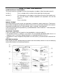
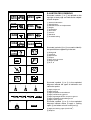
2002 YFA1(P) 3FA-AE1 SUPPLEMENTARY SERVICE MANUAL FOREWORD This Supplementary Service Manual has been prepared to introduce new service and new data for the YFA1(P) 2002. For complete information on service procedures, it is necessary to use this Supplementary Service Manual together with the following manual. YFA1W SERVICE MANUAL: 3FA-ME1 YFA1(P) 2002 SUPPLEMENTARY SERVICE MANUAL 2001 by Yamaha Motor Co., Ltd. First Edition, May 2001 All rights reserved. Any reproduction or unauthorized use without the written permission of Yamaha Motor Co., Ltd. is expressly prohibited. EB001000 NOTICE This manual was produced by the Yamaha Motor Company primarily for use by Yamaha dealers and their qualified mechanics. It is not possible to include all the knowledge of a mechanic in one manual, so it is assumed that anyone who uses this book to perform maintenance and repairs on Yamaha machine has a basic understanding of the mechanical ideas and the procedures of machine repair. Repairs attempted by anyone without this knowledge are likely to render the machine unsafe and unfit for use. Yamaha Motor Company, Ltd. is continually striving to improve all its models. Modifications and significant changes in specifications or procedures will be forwarded to all authorized Yamaha dealers and will appear in future editions of this manual where applicable. NOTE: Designs and specifications are subject to change without notice. IMPORTANT INFORMATION Particularly important information is distinguished in this manual by the following notations. The Safety Alert Symbol means ATTENTION! BECOME ALERT! YOUR SAFETY IS INVOLVED! WARNING CAUTION: NOTE: Failure to follow WARNING instructions could result in severe injury or death to the machine operator, a bystander or a person inspecting or repairing the machine. A CAUTION indicates special precautions that must be taken to avoid damage to the machine. A NOTE provides key information to make procedures easier or clearer. HOW TO USE THIS MANUAL CONSTRUCTION OF THIS MANUAL This manual consists of chapters for the main categories of subjects. (See “Illustrated symbols”) 1st title 1: This is a chapter with its symbol on the upper right of each page. 2nd title 2: This title appears on the upper of each page on the left of the chapter symbol. (For the chapter “Periodic inspection and adjustment” the 3rd title appears.) 3rd title 3: This is a final title. MANUAL FORMAT All of the procedures in this manual are organized in a sequential, step-by-step format. The information has been compiled to provide the mechanic with an easy to read, handy reference that contains comprehensive explanations of all disassembly, repair, assembly, and inspections. A set of particularly important procedure 4 is placed between a line of asterisks “*” with each procedure preceded by “●”. IMPORTANT FEATURES ● Data and a special tool are framed in a box preceded by a relevant symbol 5. ● An encircled numeral 6 indicates a part name, and an encircled alphabetical letter data or an alignment mark 7, the others being indicated by an alphabetical letter in a box 8. ● A condition of a faulty component will precede an arrow symbol 9 and the course of action will follow it. EXPLODED DIAGRAM Each chapter provides exploded diagrams before each disassembly section for ease in identifying correct disassembly and assembly procedures. 1 EB003000 2 GEN INFO ILLUSTRATED SYMBOLS Illustrated symbols 1 to 9 are printed on the top right of each page and indicate the subject of each chapter. SPEC 3 4 CHK ADJ 1 General information 2 Specifications 3 Periodic checks and adjustments 4 Engine 5 Carburetion 6 Drive train 7 Chassis 8 Electrical 9 Troubleshooting ENG 5 6 CARB DRIV 7 8 CHAS – ELEC + 0 Illustrated symbols 0 to F are used to identify the specifications appearing in the text. A B 0 Filling fluid A Lubricant B Special tool C Torque D Wear limit, clearance E Engine speed F Ω, V, A C D 9 TRBL SHTG T. R. E F G H G E J K B M L M M LS N Illustrated symbols G to M in the exploded diagrams indicate the types of lubricants and lubrication points. I S O LT New G Apply engine oil H Apply gear oil I Apply molybdenum disulfide oil J Apply wheel bearing grease K Apply lightweight lithium soap base grease L Apply molybdenum disulfide grease M Apply silicon grease Illustrated symbols N to O in the exploded diagrams indicate where to apply a locking agent N and when to install a new part O. N Apply the locking agent (LOCTITE) O Replace CONTENTS GENERAL INFORMATION ..............................................................................1 MACHINE IDENTIFICATION ....................................................................1 MODEL LABEL .....................................................................................1 SPECIFICATIONS ............................................................................................2 GENERAL SPECIFICATIONS ..................................................................2 MAINTENANCE SPECIFICATIONS .........................................................3 ENGINE ................................................................................................3 CHASSIS ..............................................................................................5 ELECTRICAL ........................................................................................6 CABLE ROUTING .....................................................................................8 PERIODIC CHECKS AND ADJUSTMENTS ..................................................14 INTRODUCTION .....................................................................................14 PERIODIC MAINTENANCE/LUBRICATION INTERVALS ......................14 CHASSIS .................................................................................................15 ADJUSTING THE FRONT BRAKE .....................................................15 CHASSIS ........................................................................................................16 STEERING SYSTEM ..............................................................................16 ELECTRICAL .................................................................................................17 CHECKING THE SWITCH ......................................................................17 CHECKING THE SWITCH ..................................................................17 CHECKING A SWITCH SHOWN IN THE MANUAL ...........................17 SIGNAL SYSTEM ...................................................................................18 CIRCUIT DIAGRAM ............................................................................18 CHECKING THE SIGNAL SYSTEM ...................................................19 YFA1(P) 2002 WIRING DIAGRAM MACHINE IDENTIFICATION GEN INFO GENERAL INFORMATION MACHINE IDENTIFICATION MODEL LABEL The model label 1 is affixed to the frame. This information will be needed to order spare parts. –1– GENERAL SPECIFICATIONS SPEC SPECIFICATIONS GENERAL SPECIFICATIONS Model Model code number Engine: Engine type Cylinder arrangement Displacement Bore × stroke Compression ratio Compression pressure Starting system Transmission: Primary reduction system Primary reduction ratio Secondary reduction system Secondary reduction ratio Clutch type Transmission type Operation Single speed automatic Reverse ratio Tire: Type Size Front Rear Manufacturer (type) Front Rear Wear limit Electrical: Ignition system Generator system Battery capacity Battery type Headlight type Headlight bulb type Bulb wattage (quantity) Headlight Tail/brake light Neutral indicator light Reverse indicator light YFA1 (P) 2002 3FAY (CDN, Europe and Oceania) Air-cooled 4-stroke, SOHC Forward-inclined single cylinder 124 cm3 49 × 66 mm (1.93 × 2.60 in) 9.0 : 1 850 kPa (8.5 kg/cm2, 121 psi) at 570 r/min Electric starter Helical gear/spur gear 43/14 × 40/17 (7.226) Chain drive 32/12 (2.666) Dry, centrifugal automatic Single speed automatic (V-belt) Centrifugal automatic type 2.303 ~ 0.821 49/14 × 49/15 × 40/17 (26.902) Tubeless AT20 × 7–8 AT22 × 10–8 DUNLOP (KT536A) DUNLOP (KT537A) 3.0 mm (0.12 in) CDI A.C. magneto generator 12 V 12 AH 12N12C-4A-2 Bulb type Incandescence 12 V 25 W/25 W (1 pc.) 12 V 5 W/21 W (1 pc.) 12 V 3.4 W (1 pc.) 12 V 3.4 W (1 pc.) –2– MAINTENANCE SPECIFICATIONS SPEC MAINTENANCE SPECIFICATIONS ENGINE Model Cylinder: Bore size <Wear limit> Measuring point “ ” Camshaft: Drive method Cam dimensions Intake “A” “B” “C” Exhaust “A” “B” “C” Camshaft runout limit Rocker arm/rocker arm shaft: Inside diameter (rocker arm) Outside diameter (shaft) Arm-to-shaft clearance Valve, valve seat, valve guide: Valve clearance (cold) Intake Exhaust Valve dimensions “A” head diameter Intake Exhaust YFA1 (P) 2002 48.99 ~ 49.03 mm (1.9287 ~ 1.9303 in) <49.15 mm (1.935 in)> 45 mm (1.77 in) * Chain drive (left) C A B 26.169 ~ 26.269 mm (1.0303 ~ 1.0342 in) 21.061 ~ 21.161 mm (0.8292 ~ 0.8331 in) 5.159 ~ 5.279 mm (0.2031 ~ 0.2078 in) 26.169 ~ 26.269 mm (1.0303 ~ 1.0342 in) 21.061 ~ 21.161 mm (0.8292 ~ 0.8331 in) 5.159 ~ 5.279 mm (0.2031 ~ 0.2078 in) 0.03 mm (0.0012 in) 10.000 ~ 10.015 mm (0.3937 ~ 0.3943 in) 9.981 ~ 9.991 mm (0.3930 ~ 0.3933 in) 0.009 ~ 0.034 mm (0.0004 ~ 0.0013 in) 0.08 ~ 0.12 mm (0.0031 ~ 0.0047 in) 0.10 ~ 0.14 mm (0.0039 ~ 0.0055 in) 25.9 ~ 26.1 mm (1.02 ~ 1.03 in) 21.9 ~ 22.1 mm (0.86 ~ 0.87 in) A “B” face width Intake Exhaust B 1.4 ~ 3.0 mm (0.06 ~ 0.12 in) 1.7 ~ 2.8 mm (0.07 ~ 0.11 in) “C” seat width Intake Exhaust C 0.9 ~ 1.1 mm (0.035 ~ 0.043 in) 0.9 ~ 1.1 mm (0.035 ~ 0.043 in) “D” margin thickness Intake Exhaust 0.4 ~ 0.8 mm (0.016 ~ 0.031 in) 0.8 ~ 1.2 mm (0.031 ~ 0.047 in) D Outside diameter (valve stem) Intake Exhaust 4.975 ~ 4.990 mm (0.196 in) 4.960 ~ 4.975 mm (0.195 ~ 0.196 in) –3– MAINTENANCE SPECIFICATIONS Model SPEC YFA1 (P) 2002 Inside diameter (valve guide) Intake Exhaust Stem-to-guide clearance Intake Exhaust Stem runout limit Valve seat width Intake Exhaust Piston: Piston size “D” Measuring point “H” 5.000 ~ 5.012 mm (0.197 in) 5.000 ~ 5.012 mm (0.197 in) 0.010 ~ 0.037 mm (0.004 ~ 0.0014 in) 0.025 ~ 0.052 mm (0.0010 ~ 0.0020 in) 0.01 mm (0.0004 in) 0.9 ~ 1.1 mm (0.035 ~ 0.043 in) 0.9 ~ 1.1 mm (0.035 ~ 0.043 in) 48.96 ~ 49.00 mm (1.927 ~ 1.929 in) 6 mm (0.24 in) From bottom of the piston. H D Piston-to-cylinder clearance <Wear limit> Over size 2nd 4th Piston off-set Piston off-set direction Inside diameter (piston pin bore) Outside diameter (piston pin) Piston pin-to-piston clearance <Limit> Piston ring: Type Top ring 2nd ring Dimension (B × T) Top ring 0.020 ~ 0.040 mm (0.0008 ~ 0.0016 in) <0.15 mm (0.006 in)> 49.5 mm (1.95 in) 50.0 mm (1.97 in) 0.5 mm (0.02 in) Intake side 13.002 ~ 13.013 mm (0.5119 ~ 0.5123 in) 12.996 ~ 13.000 mm (0.5117 ~ 0.5118 in) 0.002 ~ 0.017 mm (0.0001 ~ 0.0006 in) <0.07 mm (0.003 in)> Barrel Taper B T Second ring 1.0 × 2.0 mm (0.039 × 0.079 in) B 1.0 × 2.0 mm (0.039 × 0.079 in) B 2.0 × 2.2 mm (0.079 × 0.087 in) T Oil ring T End gap (installed) Top ring Second ring Oil ring 0.15 ~ 0.30 mm (0.006 ~ 0.012 in) 0.15 ~ 0.30 mm (0.006 ~ 0.012 in) 0.20 ~ 0.80 mm (0.008 ~ 0.031 in) –4– MAINTENANCE SPECIFICATIONS Model Side clearance Top ring Second ring Carburetor: I.D. mark Main jet Main air jet Jet needle Needle jet Cutaway Pilot air jet Pilot outlet Pilot jet Bypass 1 Pilot screw Valve seat size Starter jet Float height Fuel level SPEC YFA1 (P) 2002 0.03 ~ 0.07 mm (0.0012 ~ 0.0027 in) 0.02 ~ 0.06 mm (0.0008 ~ 0.0024 in) (M.J.) (M.A.J.) (J.N.) (N.J.) (C.A.) (P.A.J.) (P.O.) (P.J.) (B.P.1) (P.S.) (V.S.) (G.S.) (F.H.) (F.L.) Engine idling speed Intake vacuum 3FA02 #82.5 ø1.3 4H36-3 N-6 2.5 #130 ø0.7 #12.5 1.1 2 and 1/2 turns out 1.8 #45 21.8 mm (0.858 in) 4.0 ~ 6.0 mm (0.16 ~ 0.24 in) With special tool 1,650 ~ 1,750 r/min 26.7 kPa (200 mm Hg, 7.88 in Hg) CHASSIS Model Suspension: Suspension travel Front Rear Free length (spring) Front Rear Installed length Rear Spring rate Front Rear Stroke Front Rear Optional spring Front Rear YFA1 (P) 2002 41 mm (1.614 in) 60 mm (2.362 in) 148 mm (5.827 in) 205 mm (8.071 in) 180 mm (7.09 in) 29.4 N/mm (3.0 kg/mm, 167.9 lb/in) 36.3 N/mm (3.7 kg/mm, 207.3 lb/in) 0.0 ~ 41 mm (0.0 ~ 1.614 in) 0.0 ~ 60 mm (0.0 ~ 2.362 in) No No –5– MAINTENANCE SPECIFICATIONS Model Drive chain: Type/manufacturer Number of links Chain slack 10-link length limit Brake lever: Free play Front brake Rear brake SPEC YFA1 (P) 2002 520V6/DAIDO 74 links 30 mm (1.18 in) 150.1 mm (5.909 in) 5 ~ 8 mm (0.20 ~ 0.31 in) At lever pivot. 5 ~ 8 mm (0.20 ~ 0.31 in) At lever pivot. ELECTRICAL Model C.D.I.: Magneto model/manufacturer Pickup coil resistance (lead color) C.D.I. unit model/manufacturer Ignition coil: Model/manufacturer Minimum spark gap Primary coil resistance Secondary coil resistance Spark plug cap: Material Resistance Charging system: Type Magneto model/manufacturer Charging coil resistance (lead color) Charging current Day (Minimum) (Maximum) Night (Minimum) (Maximum) Lighting coil resistance (lead color) Lighting voltage (Minimum) (Maximum) Standard output YFA1 (P) 2002 F3FA/YAMAHA 248 ~ 372 Ω at 20 °C (68 °F) (White–Red) 3FA/YAMAHA 2JN/YAMAHA 6.0 mm (0.24 in) 0.18 ~ 0.28 Ω at 20 °C (68 °F) 6.32 ~ 9.48 kΩ at 20 °C (68 °F) Resin 10 kΩ at 20 °C (68 °F) A.C. magneto generator F3FA/YAMAHA 0.96 ~ 1.44 Ω at 20 °C (68 °F) (Black–White) 0.8 A at 3,000 r/min 2.0 A at 8,000 r/min 0.6 A at 3,000 r/min 3.5 A at 8,000 r/min 0.72 ~ 1.08 Ω at 20 °C (68 °F) (Black–Yellow) 12.0 V at 3,000 r/min 14.8 V at 8,000 r/min 14 V 125 W at 5,000 r/min –6– MAINTENANCE SPECIFICATIONS Model SPEC YFA1 (P) 2002 16(V) Charging current (A) Lighting voltage (V) VL 12(V) 4(A) 8(V) 3(A) Ich (Day) 2(A) 4(V) Ich (Night) 1(A) 0 Rectifier/regulator: Model/manufacturer Regulator type No load regulated voltage (DC) No load regulated voltage (AC) Rectifier capacity (DC) Rectifier capacity (AC) Withstand voltage Electric starting system: Type Starter motor Model/manufacturer Output Armature coil resistance Overall length (brush) <Limit> Brush spring pressure Commutator diameter <Wear limit> Mica undercut Starter relay Model/manufacturer Amperage rating Coil resistance Starting circuit cut-off relay Model/manufacturer Coil resistance Diode 2 4 6 8 10 Engine speed (× 1000 r/min) EHU–01TR31/MATSUSHITA Semi conductor short circuit type 14.0 ~ 15.0 V 13.0 ~ 14.0 V 8.0 A 8.0 A 200 V Constant mesh 3FA1/YAMAHA 0.4 kW 0.019 ~ 0.023 Ω at 20 °C (68 °F) 10.0 mm (0.39 in) <3.5 mm (0.14 in> 552 ~ 828 g 22.0 mm (0.87 in) <21.0 mm (0.83 in)> 1.5 mm (0.06 in) MS5D–611/JIDECO 100 A 3.87 ~ 4.73 Ω at 20 °C (68 °F) ACA1211–9/MATSUSHITA 72 ~ 88 Ω at 20 °C (68 °F) No –7– CABLE ROUTING CABLE ROUTING 1 Throttle cable 2 Band 3 Breather hose 4 Rear brake switch lead 5 Rear brake cable 6 Front brake cable 7 Front brake switch lead –8– SPEC CABLE ROUTING 1 Front brake cable 2 Band 3 Rear brake cable 4 Rear brake switch lead 5 CDI unit 6 Wire harness 7 Main switch 8 Front brake switch lead SPEC È Pass leads in front of the brake cable and connect them inside the headlight body. É Pass the inlet and outlet hoses between the brake cables. Ê Clamp the front brake switch lead, rear brake switch lead, main switch lead, handlebar switch lead, and wire sub-leads with a plastic clamp. Ë Pass the leads between the throttle cable and front brake cable. –9– CABLE ROUTING 1 Throttle cable 2 Rectifier/regulator 3 Starting motor 4 CDI magneto lead 5 Clamp 6 Ignition coil SPEC È Fasten the wire harness, starting motor lead and transmission case breather hose to the frame with a plastic band. – 10 – CABLE ROUTING 1 Taillight 2 Reverse relay 3 Starting circuit cut-off relay 4 Fuse holder 5 Starter relay 6 Wire harness 7 Breather hose (transmission case) 8 Neutral switch lead 9 Select lever switch 0 Overflow hose A Battery breather hose B Band SPEC C Battery negative lead D Reverse switch lead È Hold the clamp and ground lead to the crankcase with a screw. É Pass the overflow hose between the engine and swingarm. Ê Pass the battery breather hose through the guides. – 11 – CABLE ROUTING 1 Inlet hose 2 Outlet hose 3 Fuel hose 4 Breather hose (crankcase) 5 Overflow hose 6 Guide 7 Rear brake cable 8 Front brake cable (left) 9 Front brake cable (right) 0 CDI unit A Band SPEC È Pass the breather hose through the hole of handlebar cover and then between the steering column and fuel tank. É Pass the overflow hose left side of the engine stay. Ê Pass the brake cable inside the swingarm. – 12 – CABLE ROUTING 1 CDI unit 2 Band 3 Starter cable 4 Wire harness 5 Breather hose (transmission case) 6 Ignition coil 7 Battery positive lead 8 Battery negative lead 9 Breather hose (crankcase) 0 Throttle cable A Fuse holder B Starting circuit cut-off relay SPEC C Reverse relay È Pass the breather hose between the throttle cable and starter cable. – 13 – INTRODUCTION/ PERIODIC MAINTENANCE/LUBRICATION INTERVALS CHK ADJ EB300000 PERIODIC CHECKS AND ADJUSTMENTS INTRODUCTION This chapter includes all information necessary to perform recommended inspections and adjustments. These preventive maintenance procedures, if followed, will ensure more reliable vehicle operation and a longer service life. The need for costly overhaul work will be greatly reduced. This information applies to vehicles already in service as well as to new vehicles that are being prepared for sale. All service technicians should be familiar with this entire chapter. EB301000 PERIODIC MAINTENANCE/LUBRICATION INTERVALS INITIAL ITEM ROUTINE Valves* • Check valve clearance. • Adjust if necessary. Spark plug • Check condition. • Adjust gap and clean. • Replace if necessary. 1 month Air filter element • Clean. (for engine and V-belt • Replace if necessary. compartment) 3 months EVERY 6 months 6 months Every 20 ~ 40 hours (More often in wet or dusty areas.) Carburetor* • Check idle speed/starter operation. • Adjust if necessary. Cylinderhead cover breather system* • Check breather hose for cracks or damage. • Replace if necessary. Exhaust system* • Check leakage. • Retighten if necessary. • Replace gasket if necessary. Fuel line* • Check fuel hose for cracks or damage. • Replace if necessary. Engine oil • Replace (Warm engine before draining). Oil strainer* • Clean. • Replace if necessary. Drive chain • Check and adjust slack/alignment/clean/lube. Transmission oil • Check oil level/oil leakage. • Replace every 12 months. Brakes* • Check operation. • Adjust if necessary. V-belt* • Check operation. • Replace if damage or excessive wear. Wheels* • Check balance/damage/runout. • Replace if necessary. Wheel bearings* • Check bearing assembly for looseness or damage. • Replace if necessary. Steering system* • • • • Knuckle shafts/ Steering shaft* • Lubricate every 6 months.** Fittings and Fasteners* • Check all chassis fittings and fasteners. • Correct if necessary. Battery* • Check specific gravity. • Check breather hose for proper operation. • Correct if necessary. Check operation. Replace if damaged. Check toe-in. Adjust if necessary. * It is recommended that these items be serviced by a Yamaha dealer. ** Lithium-soap-based grease – 14 – 1 year ADJUSTING THE FRONT BRAKE CHK ADJ CHASSIS ADJUSTING THE FRONT BRAKE 1.Check: ● Front brake lever free play a Out of specification → Adjust. Front brake lever free play: 5 ~ 8 mm (0.20 ~ 0.3 in) at lever pivot 2.Adjust: Front brake lever free play ● *********************************************** ● ● ● Loosen the locknut 1. Turn the adjuster 2 in or out until the specified brake lever free play is obtained. Turning in Free play is increased. Turning out Free play is decreased. Tighten the locknut. CAUTION: After adjusting the brake lever free play, make sure there is no drag. *********************************************** – 15 – STEERING SYSTEM CHASSIS STEERING SYSTEM 1 Handlebar holder (upper) 2 Handlebar holder (lower) 3 Steering column 4 Cable joint 5 Cable joint bracket 6 Collar 7 Steering bracket 8 Oil seal 9 Steering bracket 0 Steering knuckle A Tie-rod – 16 – CHAS CHECKING THE SWITCH ELEC – + ELECTRICAL CHECKING THE SWITCH CHECKING THE SWITCH Use a pocket tester to check the terminals for continuity. If the continuity is faulty at any point, replace the switch. Pocket tester: P/N. YU-03112, 90890-03112 NOTE: ● Set the pocket tester to “0” before starting the test. ● The pocket tester should be set to the “Ω × 1” range when testing the switch for continuity. ● Turn the switch on and off a few times when checking it. CHECKING A SWITCH SHOWN IN THE MANUAL The terminal connections for switches (main switch, handlebar switch, engine stop switch, light switch, etc.) are shown in a chart similar to the one on the left. This chart shows the switch positions in the column and the switch lead colors in the top row. For each switch position, “ ” indicates the terminals with continuity. The example chart shows that: 1 There is continuity between the “Red and Brown” leads when the switch is set to “ON”. – 17 – W R B Y/R B Y W R B Y B – 18 – OFF LO HI K J B 2 W Y/R R W 1 Y N Y/R W W/R W/L W Y R Br R R B R/W 5 R 4 RUN OFF L ON OFF 3 L R Br R/B OFF PUSH M (GRAY) Br (GRAY) Br B R/W R/B Y/R R/B R/W L B Br L Br Y/R B B B R R R Y B Br B H 7 B B 6R R L/W L/W Y Br R/W B L R/W I R/W L/W L/W Sb 8 Y Y B Br G/Y Y B Br G/Y G Br R/B Sb L/W Y G/L (RED) Br G/W B (GRAY) B G/Y Br (GRAY) R/B Br E Br F B G/W G/L Br G/L G/W G/Y R/B W/L W/L B W/R W/L W/R W/R D B G/W B C B 9 L L L Sb Br O O B O G/Y 0 A 3 Main switch 4 Fuse 5 Battery 9 CDI unit B Neutral indicator light C Neutral switch D Select lever switch E Reverse indicator light F Reverse relay G Reverse switch H Front brake light switch I Tail/brake light L Engine stop switch W/R W/L G/W R/B B SIGNAL SYSTEM ELEC – + EB806000 SIGNAL SYSTEM CIRCUIT DIAGRAM SIGNAL SYSTEM ELEC – + CHECKING THE SIGNAL SYSTEM 1.If the tail/brake light fails to come on: 1.Bulb and bulb socket ● NO CONTINUITY Check the bulb and bulb socket for continuity. CONTINUITY Replace the bulb and/or bulb socket. NO CONTINUITY 2.Brake light switches Refer to “CHECKING THE SWITCH”. CONTINUITY Replace the brake switch. 3.Voltage ● Connect the pocket tester (DC 20V) to the bulb socket connector. Tester (+) lead → Yellow terminal 1 Tester (–) lead → Black terminal 2 ● ● OUT OF SPECIFICATION Turn the main switch to “ON”. Check the voltage (12 V) of the “Yellow” lead on the bulb socket connector. The wiring circuit from the main switch to the bulb socket connector is faulty, repair it. MEETS SPECIFICATION This circuit is not faulty. – 19 – YFA1(P) 2002 WIRING DIAGRAM W/R W/L W/L W/R R/B B 1 W/R W/R W/L W/L R/B B W W Y B W B 9 G/Y Y O A B 4 0 R R R W Y R B R 3 ON OFF B R 2 R R R 6R 5 Br (GRAY) R Y/R L/W R/W R/W 8 R/W B R R/B Br B (GRAY) B L/W Sb L/W B Br B L/W B Br W O G/W Y W Y/R R O G/Y W/R W/L G/W Sb L/W 7 Br R/B 1 2 3 4 5 6 7 8 9 0 A B C D E F G H I J K L M N B Br J Y/R K Br R/B L OFF LO HI R/W Br M RUN OFF B Y Br Y/R L R/W R/B B Y N Y Br B G/Y Br B B L B Y/R D B B (GRAY) Y L E Br G/Y B Br G H OFF PUSH G/W Br G/Y Br G/L G/W B L Y Sb L (GRAY) R/B R/W B Y Br G/L Br F L G/L (RED) L C B G/W I B COLOR CODE B ............Black Br ...........Brown L.............Blue O............Orange R ............Red Sb ..........Sky blue W ...........White Y ............Yellow G/L.........Green/Blue G/W .......Green/White G/Y ........Green/Yellow L/W ........Blue/White R/B.........Red/Black R/W........Red/White W/L ........White/Blue W/R........White/Red Y/R.........Yellow/Red AC magneto Rectifier/regulator Main switch Fuse Battery Starter relay Starter motor Starting circuit cut-off relay CDI unit Ignition coil Spark plug Neutral indicator light Neutral switch Reverse switch Reverse indicator light Reverse relay Brake lever switch Front brake light switch Tail/brake light Handlebar switch (left) Lights switch Engine stop switch Start switch Headlight