1
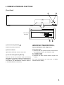
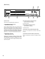
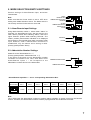
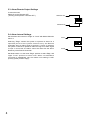
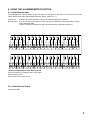
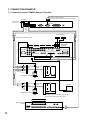
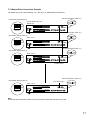
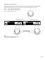
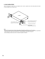
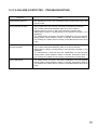
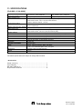
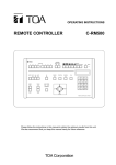
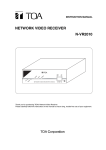
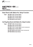
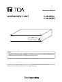
Instruction Manual
ALARM INPUT UNIT
C-AL80(L)
C-AL80(H)
POWER
ON
OFF
Note
The C-AL80 Alarm Input Unit is designed to be used in conjunction with TOA's C-RM500 Remote
Controller to enable their alarm operations or remote control. Thus, the C-AL80 Alarm Input Unit can
only be used while connected to a C-RM500 Remote Controller.
Thank you for purchasing TOA's Alarm Input Unit. Please carefully follow the instructions in this manual
in order to ensure long, trouble-free use of your Alarm Input Unit.
TABLE OF CONTENTS
1. SAFETY PRECAUTIONS ................................................................................ 3
2. GENERAL DESCRIPTION ............................................................................. 4
3. HANDLING PRECAUTIONS .......................................................................... 4
4. NOMENCLATURE AND FUNCTIONS
Front Panel ............................................................................................................... 5
Rear Panel ............................................................................................................... 6
5. MODE SELECTION SWITCH SETTINGS
5.1. Alarm/Remote Input Settings ............................................................................
5.2. Abbreviation Number Settings ..........................................................................
5.3. Alarm/Remote Output Settings ..........................................................................
5.4. Alarm Interval Settings .......................................................................................
7
7
8
8
6. USING THE ALARM/REMOTE FUNCTION
6.1. Alarm/Remote Input .......................................................................................... 9
6.2. Alarm/Remote Output ....................................................................................... 9
7. CONNECTION EXAMPLES
7.1. Example of the Combination with the C-SC80 Remote Controller .................. 10
7.2. Example of the Combination with the C-SC50A Remote Controller ............... 11
8. MASTER/SLAVE CONNECTIONS
8.1. Unit Number Settings ...................................................................................... 12
8.2. Master/Slave Terminal Connections ............................................................... 12
9. RACK MOUNTING ........................................................................................... 14
10. IF A FAILURE IS DETECTED… (TROUBLESHOOTING) .................. 15
11. SPECIFICATIONS ............................................................................................ 16
Accessories ............................................................................................................. 16
2
1. SAFETY PRECAUTIONS
• Before installation or use, be sure to carefully read all the instructions in this section in order to ensure long,
trouble-free operation.
• Be sure to follow all the precautionary instructions in this section, which contain important warnings
regarding safety.
• After reading, keep this manual handy for future reference.
Safety Symbol and Message Conventions
Safety symbols and messages are used in this manual to prevent bodily injury and property damage which
could result from mishandling. The conventions of the symbols and messages are described below. Before
doing anything else, read this section first so you are thoroughly aware of the potential safety hazards as well
as understanding the safety symbols and messages.
WARNING
Indicates a potentially hazardous situation which could result in death
or serious personal injury if ignored or mishandled.
When Installing the Alarm Input Unit…
• Do not expose the unit to rain or an environment where it may be splashed by water or other liquids, as
doingotherwise may result in fire or electric shock.
• Use the unit only with the voltage specified on the unit. Using a voltage other than that which is specified
may result in fire or electric shock.
• Do not cut, kink, or otherwise damage or modify the power supply cord. Also, avoid using the power cord in
close proximity to heaters, and never place heavy objects, including the unit itself, on the power cord as
doing otherwise may result in fire or electric shock.
• Avoid installing or mounting the unit in unstable locations, such as on a rickety table or a slanted surface.
Failure to follow this instruction may result in the unit falling down and causing personal injury.
• Do not install the unit in close proximity to medical equipment since the electromagnetic wave from the unit
may adversely affect the medical equipment.
When Using the Alarm Input Unit…
• Do not place cups, bowls, or other containers of liquids or metal objects on top of the unit. If they
accidentally spill into the unit, this may cause a fire or electric shock.
• Do not insert foreign objects, such as metal objects and flammable materials, into the unit through the unit's
ventilation slots, as this may result in fire or electric shock.
• Do not touch a power supply plug during thunder and lightning, as this may result in an electric shock.
• Do not open nor modify the unit's case to prevent a fire or electric shock because there are high voltage
components inside the unit. Refer all inspection, adjustment and repair work to the dealer from where the
unit was purchased.
• Should any of the following irregularities be found during use, immediately switch off the power, disconnect
the power supply cord from the AC outlet and contact your TOA dealer. Do not attempt to further use the
unit because a fire or electric shock may result.
• If you detect smoke or a strange smell coming from the unit.
• If water or a foreign object enters the unit.
• If the unit falls or the unit case breaks.
• If the power supply cord is damaged (exposure of core or disconnection).
• If no image is displayed.
Underwriters Laboratories Inc. (UL) has not tested the performance or reliability of the security aspects
of this product. UL has only tested for fire, shock or casualties as outlined in UL's Standard(s) for
Safety. UL Certification does not cover the performance or reliability of the security hardware and
security operating software. UL MAKES NO REPRESENTATIONS, WARRANTIES OR
CERTIFICATIONS WHATSOEVER REGARDING THE PERFORMANCE OR RELIABILITY OF ANY
SECURITY RELATED FUNCTIONS OF THIS PRODUCT.
3
CAUTION
Indicates a potentially hazardous situation which could result in
moderate or minor personal injury, and/or property damage if ignored
or mishandled.
When Installing the Alarm Input Unit
• Never insert nor remove the power supply plug with wet hands, as an electric shock may result.
• When unplugging the power supply cord, be sure to grasp the power supply plug; never pull on the cord
itself. The power supply cord may be damaged, possibly causing a fire or electric shock.
• Do not block the ventilation slots in the unit's cover. Doing otherwise may cause heat to build up inside the
unit, possibly causing a fire.
• Avoid installing the unit in humid or dusty locations, in locations exposed to the direct sunlight, near the
heaters, or in locations generating sooty smoke or steam as doing otherwise may result in fire or electric
shock.
• When moving the unit, be sure to remove its power supply cord from the wall outlet. Moving the unit with the
power cord connected to the outlet may cause damage to the power cord, resulting in fire or electric shock.
• When mounting the C-AL80 Alarm Input Unit in an equipment rack, ensure that the temperature inside the
rack is lower than its maximum ambient temperature.
When Using the Alarm Input Unit
• Do not place heavy objects on the unit. Such objects may fall or the unit may tip over, possibly resulting in
personal injury.
• Clean the inside of the unit periodically, and contact your TOA dealer regarding the cleaning. If dust is
allowed to accumulate in the unit over a long period of time, a fire may result.
• If dust accumulates on the power supply plug or in the wall AC outlet, a fire may result. Clean them
periodically. Also, insert the plug in the wall outlet securely.
• Switch off the power and unplug the power supply plug from the AC outlet for safety purposes when cleaning
or leaving the unit unused for a long period of time. A fire or electric shock may result.
L version complies with Part 15 of the FCC Rules.
Note
This equipment has been tested and found to comply with the limits for a Class A digital device,
pursuant to Part 15 of the FCC Rules. These limits are designed to provide reasonable protection
against harmful interference when the equipment is operated in a commercial environment. This
equipment generates, uses, and can radiate radio frequency energy and, if not installed and used in
accordance with the instruction manual, may cause harmful interference to radio communications.
Operation of this equipment in a residential area is likely to cause harmful interference in which case the
user will be required to correct the interference at his own expense.
Modifications
Any modifications made to this device that are not approved by TOA Corporation may void the authority
granted to the user by the FCC to operate this equipment.
2. GENERAL DESCRIPTION
Using no-voltage contact inputs, TOA's C-AL80 Alarm Input Unit activates the remote controller's alarm
facilities or remotely controls the remote controller. The C-AL80 has a total of 32 alarm or remote inputs. By
making master-sub connections, up to 8 C-AL80 units can be connected to each other, creating a total of 256
alarm/ remote inputs.
3. HANDLING PRECAUTIONS
• Use the C-AL80 Unit in locations where the temperature fluctuates in the range of 0 – 40°C, and humidity is
under 90% (no condensation must be formed).
• When permanently installing the Unit, avoid blocking ventilation slots in the Unit's cover and bottom panel,
and keep the Unit's front, rear, and sides at least 10 cm from the wall. Doing otherwise may cause heat to
build up inside the Unit and result in the Unit's failure.
4
4. NOMENCLATURE AND FUNCTIONS
[Front Panel]
1
2
POWER
ON
OFF
Cover
The inside of
the cover
LEVEL
REMOTE OFF
ABBREVIATION No.9001
REMOTE
ALARM
ABBREVIATION No.1
REMOTE ON
EDGE
ON
1 2 3 4
1 2 3 4
4
(1) Power Switch [ON/OFF
]
Used to turn power on and off.
(2) Power Indicator
Lights when the Power switch is set to ON.
(3) Unit No. Setting Switch [ON/OFF]
Used to set the unit number when performing
master/slave connections (cascade connections) for
multiple C-AL80 units. Up to 8 units can be
connected for the "Master/Slave" relations. (Refer to
p. 19; Master/Slave Connections.)
OFF
UNIT No.
3
(4) Mode Selection Switch [Alarm/Remote,
Abbreviation No. 1–/Abbreviation No. 9001–,
Remote ON/Remote OFF, Edge/Level]
(From left to right)
1) Switches the rear panel-mounted terminal block
input between "Alarm" and "Remote" mode.
2) It cannot be used.
3) It cannot be used.
4) Switches the alarm interval between "Edge" and
"Level."
For more information on, refer to p. 9; Mode
Selection Switch Setting.
5
[Rear Panel]
11
7
ALARM/ / REMOTE IN
MASTER / SLAVE
OFF
ON
TERMINATION
CAMERA SELECT OUT
5
6
(5) Power Inlet
8
ALARM / REMOTE OUT
RS-232C
9
10
(8) Camera Selection Output Terminal
[Camera Selection Output]
Connects to the supplied power supply cord.
It cannot be used.
(6) Alarm/Remote Input Terminal
[Alarm/Remote Input]
Use the Mode Selection switch (4) to perform input
function settings. When set to "Alarm" input, an
alarm can be activated from such external devices
as sensors connected to this terminal. When set to
"Remote" input, this terminal permits the selection of
the camera connected to the Remote Controller.
(Refer to p. 11; Using the Alarm/Remote Function.)
(7) Master/Slave Terminal
[Master/Slave] (Non LPS)
These input and output terminals are used to make
master/slave connections for multiple C-AL80 Units.
The master/slave connection is possible for up to 8
C-AL80 units. Both left and right terminals provide
the same function.
6
(9) Alarm/Remote Output Terminal
[Alarm/Remote Output]
It cannot be used.
(10) RS-232C Terminal [RS-232C] (Non LPS)
Connects to the Remote Controller's RS-232C
terminal.
(11) RS-485 Termination Switch [Termination]
Used for master/slave connection of multiple C-AL80
Units.
5. MODE SELECTION SWITCH SETTINGS
Perform settings of Alarm/Remote input, and alarm
intervals here.
Note
Make sure that the Power switch is set to OFF when
setting each Mode Selection switch. The Mode switch is
not correctly set if the Power switch is set to ON.
5.1. Alarm/Remote Input Settings
LEVEL
REMOTE OFF
ABBREVIATION No.9001
REMOTE
ALARM
ABBREVIATION No.1
REMOTE ON
EDGE
Using Mode Selection switch 1, select either "Alarm" or
"Remote" for Alarm/Remote input. Set the switch to the
lower "Alarm" position when selecting "Alarm," and to the
upper "Remote" position when selecting "Remote." The
"Alarm" position permits alarm indication to be displayed
and a buzzer to be sounded when there is an alarm signal
input. However, when a master/slave connection is
established, only the master unit's setting is valid.
(Factory-preset position: Alarm)
1 2 3 4
REMOTE
ALARM
1
5.2. Abbreviation Number Settings
Please fix to the "Abbreviation No. 1–,"
(Factory-preset position: "Abbreviation No. 1–,")
In the event of the slave unit, its abbreviation number
increases in increment of 32. Thus, each Alarm Unit's
Alarm/Remote inputs 1 – 32 correspond to the
abbreviation numbers shown in the below table.
ABBREVIATION No.9001
2
ABBREVIATION No.1
• Alarm/Remote input Nos. 1 – 32 vs. corresponding abbreviation Nos.
Master Unit's
Switch Setting
Master
Unit 1
1
32
Slave
Unit 2
33
64
Slave
Unit 3
65
96
Slave
Unit 4
97
Slave
Unit 5
128 129
Slave
Unit 6
160 161 192
Slave
Unit 7
193
Slave
Unit 8
224 225
256
1 2 3 4
Note
The C-AL80 uses the abbreviation numbers to perform alarm activation or remote control for the Remote
Control. Therefore, the abbreviation numbers must be preprogrammed into the Remote Controller.
7
5.3. Alarm/Remote Output Settings
It cannot be used.
Please fix to the "Remote OFF"
(Factory-preset position: "Remote OFF")
REMOTE OFF
3
REMOTE ON
5.4. Alarm Interval Settings
Set the alarm time interval to "Edge" or "Level" with Model Selection
switch 4.
Selecting "Edge" causes the system to operate on alarm for a
specified period of time (Alarm Interval set by the Remote
Controller) when an alarm signal is received. If "Level" is selected,
the system continues to operate on alarm as long as an alarm signal
is input. In this event, the alarm cannot be reset with the Alarm
Reset key of the Remote Controller.
Set Mode switch 4 to the lower "Edge" position to select Edge, and
upper "Level" position to select Level. When a master/slave
connection is established, only the master unit's setting is valid.
(Factory-preset position: Edge)
8
LEVEL
4
EDGE
6. USING THE ALARM/REMOTE FUNCTION
6.1. Alarm/Remote Input
The Alarm/Remote input terminals on the rear panel are designed to be used for both alarm and remote
inputs. Select either input with the Mode Selection switch. (Refer to p. 7.)
Alarm input:
Remote input:
1
17
2
18
Enables spot alarm operations using such external equipment as sensors.
Selects the channel and position of the camera corresponding to the abbreviation number
when shorted to GND.
(Only the channel is selected for other cameras than the Combination Camera.)
4
G
N
D
20
G
N
D
3
19
5
21
6
22
7
23
8
G
N
D
24
G
N
D
9
25
10
26
11
27
12
G
N
D
28
G
N
D
13
29
14
30
15
31
16
G
N
D
32
G
N
D
• Electrical Alarm/Remote Input Specifications
Input: 32 channels, no-voltage make contact input
Open Voltage: 5 VDC
Short-circuit Current: Max. 5 mA
6.2. Alarm/Remote Output
It cannot be used.
9
7. CONNECTION EXAMPLE
7.1. Connection to the C-RM500 Remote Controller
RS-232C reverse cable
D-sub 9 pins/female to D-sub 9 pins/female
C-RM500
Camera control
terminal
Switcher control terminal
GND
Alarm input terminal
RS-232C
GND
Fixed cameras
Twisted pair shielded cable
Multi-Switcher
C-MS161D
Video input
Input
Input
+ GND – + GND –
Input Output
Dedicated remote control terminal
Video input/output
Alarm input/output
Monitor output
Remote control termination: OFF
A
1
B
2
A
3
B
4
1
Camera control
cable
Alarm input
cable
4
6
5
9
5,10
Combination camera
1
1
2
3
Sensor
Camera control
cable
Alarm input
cable
Monitor
4
6
4
5
9
5,10
Combination camera
Sensor
The use of each camera's alarm input permits up to
8 sensors to be connected for each camera.
Sensor
Alarm Input Unit
C-AL80
Alarm/Remote Input
RS-232C
Master Unit
10
7.2. Master/Slave Connection Example
For details about unit number settings, etc., refer to p. 19; Master/Slave Connections.
RS-485 Termination switch (11)
Unit Number Setting switch (3)
C-AL80 Alarm Input Unit
Master Unit
ON
1 2 3 4
OFF
ON
Termination
OFF
Unit No.
RS-485 Termination switch (11)
Unit Number Setting switch (3)
OFF
Slave Unit 1
ON
Termination
ON
1 2 3 4
OFF
Unit No.
RS-485 Termination switch (11)
Unit Number Setting switch (3)
OFF
Slave Unit 2
ON
Termination
ON
1 2 3 4
OFF
Unit No.
To Slave Unit 3
RS-485 Termination switch (11)
Unit Number Setting switch (3)
From Slave Unit 6
Slave Unit 7
OFF
ON
Termination
ON
1 2 3 4
OFF
Unit No.
Note
Set the RS-485 Termination switch of only the master unit and the last slave unit to ON.
11
8. MASTER/SLAVE CONNECTIONS
An entire system can have up to 256 Alarm/Remote inputs through master/slave connections (cascade
connections) of up to 8 C-AL80 Units.
8.1 Unit Number Settings
Be sure to set the unit number when making master/slave connections.
Because each component is factory-preset to the unit number for individual use (same setting as the master
unit), change the number when making a master/slave connection.
Note
Make sure that the Power switch is set to OFF when changing each switch
setting. The system does not operate correctly if the change is made with the
Power switch set to ON.
ON
1 2 3 4
OFF
Unit Number
Settings
Use Unit No. Setting switches 1 – 3 to perform settings. Refer to the following table for switch settings of the
master unit and slave units. Assign slave unit numbers in consecutive order with the lowest number first. Be
sure that no numbers are duplicated.
Master Unit
Slave Unit 1
Slave Unit 2
Slave Unit 3
Slave Unit 4
Slave Unit 5
Slave Unit 6
Slave Unit 7
1 2 3 4
1 2 3 4
1 2 3 4
1 2 3 4
1 2 3 4
1 2 3 4
1 2 3 4
1 2 3 4
Unit No.
switch setting
8.2. Master/Slave Terminal Connections
Connect the Master/Slave terminals of all C-AL80 units to be included in the master/slave connection in order
of the unit number. Set the RS-485 Termination switch of the master unit and the last-connected slave unit
(highest unit number) to ON, and those of other units to OFF. Set the Termination switch to OFF when using
the unit individually. (Factory-preset position: OFF.)
Note
The system does not operate correctly when the unit number is not correctly set, when the unit numbers are
duplicated or not consecutive or when the BS-485 Termination switch is not correctly set.
12
• Master/Slave Terminal Cable Type
Use the supplied DIN plug and the twisted pair cable with plug for connection between the Master/Slave
terminals. Refer to the figure shown below and note the correct polarity when making the connection.
Pin No. 1 – Pin No. 1
Pin No. 3 – Pin No. 3
Control signal (positive)
Control signal (negative)
Do not connect pins Nos. 2, 4, and 5.
3
1
5
Master/Slave terminal
3
1
5
2
4
2
4
Master/Slave terminal
3
1
5
2
4
Note
Incorrect wiring may result in the unit's failure.
The maximum cable length is 1.2km.
13
9. RACK MOUNTING
When mounting the C-AL80 Unit in an equipment rack, remove 4 plastic feet on the bottom plate and attach
an optional MB-23B mounting bracket.
C-AL80
AR
5x12 S-tight screw
(supplied with MB-23B)
AR
M
UN
IT
C-
AL
80
M4x12 binding head screw
(supplied with MB-23B)
supplied with MB-23B
Fiber washer
(supplied with MB-23B)
Note
• Use the Alarm Input Unit in locations with ambient temperature of between +0°C and +40°C.
• Be sure to mount the Alarm Input Unit below the heat generating components, and mount the perforated
panel between the Alarm Input Unit and such a heat generating component as required.
• Avoid installing the Alarm Input Unit in locations exposed to vibration.
14
10. IF A FAILURE IS DETECTED... (TROUBLESHOOTING)
Symptom
Cause
Cannot switch power on.
• The supplied AC cord is not connected to the C-AL80 Unit's Power inlet
and AC outlet.
Cannot activate an alarm.
•
•
•
•
The C-AL80 Unit is not correctly connected to the Remote Controller.
The C-AL80 Unit's Mode Selection switch is not set to "Alarm."
[Sensor Alarm] is not set to "ON" on the Remote Controller menu.
Abbreviation number corresponding to the Remote Controller is not
registered.
• If a master/slave connection has been established, the Unit Number
Setting switch, Mode Selection switch or RS-485 Termination switch is
not correctly set. Cables are not correctly connected between the C-AL80
Units.
Cannot remotely control the • The C-AL80 Unit's is not correctly connected to the Remote Controller.
Remote Controller.
• The C-AL80 Unit's Mode Selection switch is not set to "Remote."
• Abbreviation number corresponding to the Remote Controller is not
registered.
• If a master/slave connection has bee established, the Unit Number
Setting switch, Mode Selection switch or RS-485 Termination switch is
not correctly set. Cables are not correctly connected the C-AL80 Units.
Power LED flashes.
• If a master/slave connection has been established, the Unit Number
Setting switch, Mode Selection switch or RS-485 Termination switch is
not correctly set. Cables are not correctly connected between the C-AL80
Units.
15
11. SPECIFICATIONS
[C-AL80(L), C-AL80(H)]
Power Source
(L) : AC110 – 120 V, 50/60 Hz
(H) : AC220 – 240 V, 50/60 Hz
Power Consumption
3 W(60 mA)
6 W(60 mA)
Alarm/ Remote Input
32 channels, no-voltage make contact input, open voltage : 5V DC,
short-circuit current : max. 5 mA, M3 screw terminal,
distance between barriers : 7.62 mm
Control Input/ Output
1 channel, RS-232C, D-sub connector (9P, male) (only valid for master unit),
fixse to 38,400 bps
Master/ sub Connection Terminal
2 channels, RS-485, maxmum cable length : 1200 m, DIN connector (5P)
Alarm Reset Input
1 channel, no-voltage make contact input, open voltage: 5V DC,
short-circuit current : max 5 mA, D-sub connector (25P)
Setting Switches
Master/ Sleve : 3-bits DIP switch (Selection of Master or Slave 1 – 7)
Alarm/ Remote : 1-bits DIP switch (Alarm/ Remote selection)
Alarm time : 1-bit DIP switch (Edge/ Level selection)
RS-485 terminal : Rear-mounted slide switch
(RS-485 termination, Enable/Disable selection)
Application
indoor use
Operating Temperature
0°C to +40°C
Finish
Panel : Alminum extrusion, black, 30% gloss
Case : Pre-coated steel plate, black, 30% gloss
Dimensions
420 (W) x 96.6 (H) x 335.8 (D) mm
Weight
3.6 kg
The above specifications are subject to change without notice.
• Accessories
Power cord (2 m) ........................................................................ 1
5-pin DIN plug .............................................................................. 2
RS-232C cable (2 m) .................................................................. 1
25-pin D-sub connector .............................................................. 2
Printed in Japan
133-12-859-2B