1
OPERATING INSTRUCTIONS
REMOTE CONTROLLER
A
B
WIPER
DEF
ZOOM
TELE
C
FUNCTION
D
E
AUX AUTO
FOCUS
FAR
ALARM
RESET HOLD
F
G
AF
GROUP
SELECT SEQUENCE
H
FREEZE
LENS SPEED
LOW
HIGH
POSITION
CONTROL
UP
LEFT
WIDE
C-RM500
RIGHT
CH
MENU
FULL
1
2
3
4
5
6
7
8
9
C
0
SET
NEAR
DOWN
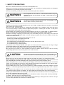
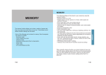
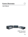
REMOTE CONTROLLER C-RM500
Please follow the instructions in this manual to obtain the optimum results from this unit.
We also recommend that you keep this manual handy for future reference.
TABLE OF CONTENTS
1. SAFETY PRECAUTIONS .................................................................................... 4
2. GENERAL DESCRIPTION .................................................................................. 5
3. FUNCTIONS ............................................................................................................ 5
4. NOMENClATURE AND FUNCTIONS
Top ............................................................................................................................... 6
Rear .............................................................................................................................. 8
Bottom (Function indications for the rear parts) ........................................................... 8
5. OPERATION
5.1. Operating the Camera
5.1.1. Selecting cameras for operation .................................................................. 9
5.1.2. Rotating the camera with the joystick ........................................................ 10
5.1.3. Activating the wiper ................................................................................... 10
5.1.4. Activating the defroster .............................................................................. 10
5.1.5. Controlling an auxiliary contact .................................................................. 10
5.1.6. Activating the automatic functions ............................................................. 11
5.1.7. Activating the zoom function ..................................................................... 11
5.1.8. Activating the focus function ...................................................................... 11
5.1.9. Changing the lens speed ........................................................................... 12
5.1.10. Activating the auto-focus function .............................................................. 12
5.1.11. Selecting the camera position ................................................................... 12
5.2. Monitor Display
5.2.1. Displaying the camera number
(only active when the Multi-Switcher is connected) ....................................13
5.2.2. Viewing the freeze screen
(only active when the Multi-Switcher is connected) ................................... 14
5.2.3. Using the Function keys ............................................................................ 15
5.2.4. Using the abbreviated numbers ................................................................ 15
5.2.5. Viewing full-screen displays ...................................................................... 16
5.2.6. Viewing multi-screen displays
(only active when the Multi-Switcher is connected)
[16-segment split-screen viewing] ............................................................. 16
[10-segment split-screen viewing] ............................................................. 17
[9-segment split-screen viewing] ............................................................... 17
[4-segment split-screen viewing] ............................................................... 18
5.2.7. Viewing sequential displays
[Sequential full-screen viewing] ................................................................. 19
[Sequential 4-segment split-screen viewing] ............................................. 19
5.3. Alarm Hold and Reset
5.3.1. Holding the alarm ...................................................................................... 20
5.3.2. Displaying alarm-activated camera images ............................................... 20
5.3.3. Resetting the alarm ................................................................................... 20
2
6. SETTINGS
6.1. Setting Items and Their Descriptions ................................................................... 21
6.2. Operating Keys and Display Screen .................................................................... 22
6.3. Basic Setting Operations ..................................................................................... 23
6.4. Setting the Functions
6.4.1. Operation mode ......................................................................................... 24
6.4.2. Switchers ................................................................................................... 25
6.4.3. Contact ...................................................................................................... 26
6.4.4. Automatic reset .......................................................................................... 27
6.4.5. Home position ............................................................................................ 28
6.4.6. I/O speed ................................................................................................... 29
6.4.7. Buzzer ....................................................................................................... 30
6.4.8. Initial screen .............................................................................................. 30
6.4.9. Channel designation .................................................................................. 31
6.4.10. Sensor alarm ............................................................................................. 32
6.4.11. Camera alarm ............................................................................................ 32
6.4.12. Camera check ........................................................................................... 33
6.4.13. Camera alarm preset ................................................................................. 34
6.4.14. Alarm signal ............................................................................................... 35
6.4.15. Alarm time ................................................................................................. 35
6.4.16. Alarm function ............................................................................................ 36
6.4.17. Alarm hold ................................................................................................. 36
6.4.18. Function key programming ........................................................................ 37
6.4.19. Abbreviation ............................................................................................... 38
6.4.20. Tour sequence ........................................................................................... 39
6.4.21. Camera menu ............................................................................................ 40
6.4.22. Password ................................................................................................... 40
7. CONNECTIONS
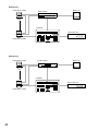
7.1. System Examples ................................................................................................ 41
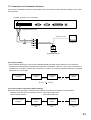
7.2. Connection to Combination Cameras .................................................................. 43
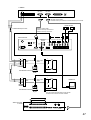
7.3. Connection to the Multi-Switcher's RS-232C Terminal ....................................... 44
7.4. Connection to the Smart Switcher's RS-232C Terminal ...................................... 46
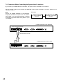
7.5. Connection When Controlling the System from 2 Locations ............................... 48
7.6. Alarm Output/Control Input Terminal Connections
7.6.1. Pin functions .............................................................................................. 49
7.6.2. Assembling D-sub connectors onto cables ............................................... 50
8. SPECIFICATIONS ................................................................................................ 51
Accessories ................................................................................................................ 51
Underwriters Laboratories Inc. (UL) has not tested the performance or reliability of the security aspects
of this product. UL has only tested for fire, shock or casualties as outlined in UL's Standard(s) for
Safety. UL Certification does not cover the performance or reliability of the security hardware and
security operating software. UL MAKES NO REPRESENTATIONS, WARRANTIES OR
CERTIFICATIONS WHATSOEVER REGARDING THE PERFORMANCE OR RELIABILITY OF ANY
SECURITY RELATED FUNCTIONS OF THIS PRODUCT.
3
1. SAFETY PRECAUTIONS
• Be sure to read the instructions in this section carefully before use.
• Make sure to observe the instructions in this manual as the conventions of safety symbols and messages
regarded as very important precautions are included.
• We also recommend you keep this instruction manual handy for future reference.
WARNING
Do not expose the unit to rain or an environment where it may be
splashed by water or other liquids, as doing so may result in fire or
electric shock.
WARNING
Indicates a potentially hazardous situation which, if mishandled, could
result in death or serious personal injury.
• Use the unit only with the voltage specified on the unit. Using a voltage higher than that which is specified
may result in fire or electric shock.
• Do not cut, kink, otherwise damage nor modify the power supply cord. In addition, avoid using the power
cord in close proximity to heaters, and never place heavy objects -- including the unit itself -- on the power
cord, as doing so may result in fire or electric shock.
• Avoid installing or mounting the unit in unstable locations, such as on a rickety table or a slanted surface.
Doing so may result in the unit falling down and causing personal injury and/or property damage.
• Should the following irregularity be found during use, immediately stop the power supply to the unit and
contact your nearest TOA dealer. Make no further attempt to operate the unit in this condition as this may
cause fire or electric shock.
· If you detect smoke or a strange smell coming from the unit.
· If water or any metallic object gets into the unit
· If the unit falls, or the unit case breaks
· If the power supply cord is damaged (exposure of the core, disconnection, etc.)
· If it is malfunctioning (no tone sounds.)
· If it is malfunctioning (no image appears.)
• To prevent a fire or electric shock, never open nor remove the unit case as there are high voltage
components inside the unit. Refer all servicing to your nearest TOA dealer.
• Do not touch a power plug during thunder and lightning, as this may result in electric shock.
• Do not place cups, bowls, or other containers of liquid or metallic objects on top of the unit. If they
accidentally spill into the unit, this may cause a fire or electric shock.
CAUTION
Indicates a potentially hazardous situation which, if mishandled, could
result in moderate or minor personal injury, and/or property damage.
• Never plug in nor remove the power supply plug with wet hands, as doing so may cause electric shock.
• When unplugging the power supply cord, be sure to grasp the power supply plug; never pull on the cord
itself. Operating the unit with a damaged power supply cord may cause a fire or electric shock.
• When moving the unit, be sure to remove its power supply cord from the wall outlet. Moving the unit with the
power cord connected to the outlet may cause damage to the power cord, resulting in fire or electric shock.
When removing the power cord, be sure to hold its plug to pull.
• Avoid installing the unit in humid or dusty locations, in locations exposed to the direct sunlight, near the
heaters, or in locations generating sooty smoke or steam as doing otherwise may result in fire or electric
shock.
• Do not place heavy objects on the unit as this may cause it to fall or break which may result in personal
injury and/or property damage. In addition, the object itself may fall off and cause injury and/or damage.
• Contact your TOA dealer as to the cleaning. If dust is allowed to accumulate in the unit over a long period of
time, a fire or damage to the unit may result.
• If dust accumulates on the power supply plug or in the wall AC outlet, a fire may result. Clean it periodically.
In addition, insert the plug in the wall outlet securely.
• Disconnect the power supply cord for safety purposes when cleaning or leaving the unit unused for 10 days
or more. Doing otherwise may cause a fire or electric shock.
4
2. GENERAL DESCRIPTION
The TOA C-RM500 Remote Controller is used to remotely control TOA's Combination cameras over
communication lines (RS-485). It can remotely control video image switching and cameras in combination with
TOA's Multi-Switcher or Smart Switcher.
3. FUNCTIONS
• Display Selection
The following screen formats can be selected for display of camera images connected to the Multi-Switcher:
full screen, 4-segment, sequential 4-segment, 9-segment, 10-segment or 16-segment split-screen and
sequential full-screen.
• Manual Operation
Controls the Combination camera's zoom, focus, pan and tilt functions.
• Camera Position Selection
Controls the Combination camera's orientation, and displays the camera image on the monitor in the
selected orientation.
• Function Key Programming
Camera numbers or camera number/position combinations can be programmed into the function keys (A –
H). Pressing the function key displays the camera image on the full screen. If position numbers have been
set, images of the selected camera orientation can be displayed.
• Abbreviated Number Display
Permits camera numbers or camera number/position combinations to be programmed for numbers 1 – 512.
Entering the programmed number followed by the SET key displays the corresponding camera number on
the full screen, and the image of selected camera orientation if the position number has been set.
• Alarm Function
Controls the display in synchronization with alarm signals received from a camera. When an alarm signal is
detected, the image of the corresponding camera takes display precedence. The C-RM500 Controller also
features an Alarm Hold function that temporarily disables channel (camera number) switching in response to
an alarm signal. This prevents the display from being forcibly switched to an alerted camera during close
inspection (when the Multi-Switcher is connected).
Equipment Which Can Be Controlled with the C-RM500
Shown below are equipment that can be controlled with the C-RM500.
Camera: C-CC501, C-CC504, C-CC551, and C-CC554
Up to 31 cameras can be connected to the unit's Camera control terminal and controlled. The use
of the C-IF500 Interface Unit will increase the number to up to 64 cameras (when the C-SS8
switcher is in use). Note that the cameras cannot be controlled if their number is greater than the
number of inputs of a connected switcher.
Switcher: C-MS90D, C-MS90S, C-MS160D, C-MS160S, and C-SS8
Only one switcher can be connected for remote camera control. However, as to the C-SS8, 1
master-designated unit and up to 7 slave-designated units can be connected to remotely control
the cameras.
About the Camera Control Terminal
The Camera control terminal is used to connect the C-CC501, C-CC504, C-CC551, or C-CC554 Combination
Camera or the C-IF500 Interface Unit. Up to 31 pieces of equipment can be connected to the terminal.
About the Descriptions in This Manual
• The explanations in this manual assume that the C-RM500 Remote Controller is connected to a
C-MS160D/S or C-MS90D/S Multi-Switcher and the C-SS8 Smart Switcher.
• Camera number: Refers to the camera input terminal number connected to the switcher.
• Position number: Combination camera orientation can be programmed for No. 1 – 255.
5
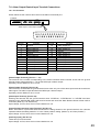
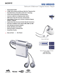
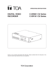
4. NOMENCLATURE AND FUNCTIONS
[Top]
1
A
B
WIPER
DEF
ZOOM
TELE
2 3
ALARM
RESET HOLD
FUNCTION
D
E
C
F
AUX AUTO
FOCUS
FAR
G
AF
LENS SPEED
LOW
HIGH
POSITION
CONTROL
CH
13
MENU
FULL
UP
LEFT
WIDE
GROUP
SELECT SEQUENCE
H
FREEZE
11 12
4 5 6 7 8 9 10
RIGHT
1
2
3
4
5
6
7
8
9
C
0
SET
NEAR
DOWN
REMOTE CONTROLLER C-RM500
14
15
WIPER
16
DEF
AUX AUTO
21 22 23 24
18
17
AF
25
FREEZE
26
POSITION
27
CONTROL
28
19
20
FULL
29
Notes
Depending on the system configuration, the operation of some keys may be disabled. The corresponding keys
are marked with the following indications.
*1 Does not function in systems using only with Combination cameras.
*2 Does not function in systems using the Smart Switcher.
*3 Functions only when connected to the Combination camera.
*4 Connect the DC power supply of 12 V/over 150 mA to either input terminal.
1. Function keys [A – H]
A single depression of one of these keys displays
the full-screen image of the key's corresponding
camera number and position number. Each key
can also be set to activate automatic operations
(panning, tracing, and sequential switching) of the
selected Combination camera.
2. Alarm reset key / Alarm indicator
Resets the system's Alarm mode. The indicator
light flashes during Alarm operation.
3. Alarm hold key / Hold indicator
Places activated Alarm inputs on hold. The
indicator light flashes during Alarm Hold.
6
4. 16-segment split-screen key *1, *2
Displays camera images in the 16-segment splitscreen format.
5. 10-segment split-screen key *1, *2
Displays camera images in the 10-segment splitscreen format. Subsequent depressions of this
key can toggle between two separate groups of
10-segment split-screen displays.
6. 9-segment split-screen key *1, *2
Displays camera images in the 9-segment splitscreen format. Subsequent depressions of this key
can toggle between two separate groups of 9segment split-screen displays.
7. 4-segment split-screen key *1, *2
Displays camera images in the 4-segment splitscreen format. Subsequent depressions of this
key can cycle through 4 separate groups of 4segment split-screen displays.
8. Sequential 4-segment split-screen key *1
Sequentially cycles through all connected
camera outputs of up to 4 groups of cameras at
a preset time interval. Program sequencing and
viewing intervals are set at the Smart Switcher
when connected.
9. Group selector key *1, *2
Switches on-screen camera groups during 4-, 9or 10-segment split-screen display.
10. Sequence key * , *
Sequences all connected camera outputs to the
full screen at the specified time interval. (Viewing
intervals are set at the switcher.)
1
2
11. CH call key * , *
Displays the camera number on the monitor for a
preset period of time. This key is convenient for
finding the camera number when no indication or
only the camera name is displayed.
1
2
12. Menu key
Displays the menu on the Remote Controller's
LCD screen for setting functions. To enable,
press lightly with a pointed object. When the
menu is opened and the desired item is selected,
the screen under the setting will be displayed.
Pressing the key again will close the setting
screen and the display will disappear.
13. LCD screen
Displays character information for the setting
menu, numeric keypad input status, current
operation, etc.
14. Zoom key *3
Sets the Combination camera's zoom lens for
"TELESCOPE" or "WIDE ANGLE" operation.
The Zoom key can only be used while the
Control indicator is on.
15. Focus key *3
Sets the Combination camera's zoom lens for
"FAR" or "NEAR" operation. The Focus key can
only be used while the Control indicator is on.
16. Lens speed key / Indicator *3
Adjusts the speed of lens operation when the
Zoom or Focus key is pressed.
17. Joystick *3
Controls the attached pan/tilt head's horizontal
and vertical movement. The joystick can only be
used while the Control indicator is on.
18. Numeric keypad [0 – 9]
Used to enter the camera number, position
number, abbreviated number, etc.
19. Clear key [C]
Used to correct entry errors. Also, turns off the
buzzer when sounded by an activated alarm.
20. SET key
Used in conjunction with the numeric keypad to
program the camera number or position number.
Also, if pressed after entering the set abbreviated
number with the numeric key, the camera image
corresponding to that number can be displayed
on the monitor.
21. Wiper key *3
Remotely controls the outdoor-use Combination
camera's wiper. This key can only be used while
the Control indicator is on.
22. Defroster key/Indicator *3
Remotely controls the outdoor-use Combination
camera's defroster. This key can only be used
while the Control indicator is on.
23. Auxiliary contact key / Indicator *3
Controls (makes or breaks) the Combination
camera's Auxiliary Contact Output 1. The
indicator is on when auxiliary contact is at make,
and off when the contact is at break. This key
can only be used when the Control indicator is
on.
24. Auto key / Indicator *3
Enables or disables the Combination camera's
automatic functions (Auto-Pan, Auto-Trace, and
Preset Sequence). The Auto key can only be
used when the Control indicator is on.
• Auto-Pan
Automatically pans a camera pan/tilt head.
• Auto-Trace
Automatically executes manual camera
operations stored in memory.
• Preset Sequence
Automatically sequences camera positions in
the order of preset position numbers.
25. Auto-focus key / Indicator *3
Enables the Combination camera's Auto-Focus
function. This key can only be used when the
Control indicator is on.
26. Freeze screen key / Indicator *1, *2
Freezes camera images. However, sequential
displays cannot be made still. The indicator
flashes when there is a freeze image on the
screen.
7
27. Position key
Orients the Combination camera toward the set
direction. The Position key can only be used
when the Control indicator is on. Pressing the
Position key without designating the position
number orients the camera toward the direction
programmed under Position No. 1 (Home
position).
28. Control key *2 / Indicator
Used to designate the camera to be manually
controlled during a multi-screen display. This key
cannot be used during a full-screen or sequential
display. Also, nothing is operated even if this key is
pressed without designating the channel number.
The indicator lights when the camera is controllable.
29. Full-screen key
Displays the designated camera output on the full
screen. This key cannot be used unless the camera
number is entered.
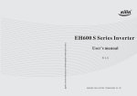
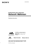
[Rear]
30 31 32 33 34
35
37
36
38
[Bottom] (Function indications for the rear parts)
GND
GND
GND
GND GND
CAMERA SWITCHER REMOTE DC IN
12V
39
REMOTE CONTROLLER
model C-RM500 120
12V
150mA Class2
SWITCHER
ALARM IN
ALARM OUT
DC IN 12V
TOA Corporation
MADE IN JAPAN
30. Camera control terminal (RS-485)
Connects to the Combination camera.
31. Switcher control terminal (RS-485)
Connects to the Multi-Switcher's dedicated
remote control terminal, and controls the
Switcher's screen display.
32. Slave unit remote control terminal
Connects to another C-RM500 Remote
Controller to be designated as a slave unit for
remote control from different locations.
33. Power input terminal [DC IN 12 V] *4
Used to supply power from a source other than
the supplied AC adapter.
34.Ground Terminal [GND]
Please ground by the cable that attached the
supplied clamp filter.
1turn
GND
Terminal
GND
clamp filter
(Please attach a clamp filter to the nearest
possible position of this controller.)
8
35. Switcher control terminal (RS-232C)
Connects to the RS-232C I/O terminal of the
Multi-Switcher and Smart Switcher to control
these switchers.
36. Alarm input terminal (RS-232C)
Connects to an alarm input unit to receive alarm
signals. This terminal is also a serial I/O terminal
that functions as an interface with external
systems.
37. Alarm output / Control input terminal
Makes contact corresponding to the alarmactivated channel (camera number).
38. AC adapter power input terminal [DC IN 12 V] *4
Insert the DC plug of the dedicated AC adapter
into this terminal.
39. Rating label
5. OPERATION
5.1. Operating the Camera
The following camera operations can be performed when the Control indicator is on.
[Operating keys]
Position key
Auto-focus key
Auto key
Auxiliary key
Defroster key
Wiper key
Control key
Full-screen key
WIPER
ZOOM
TELE
DEF
AUX AUTO
FOCUS
FAR
AF
FREEZE
POSITION
LENS SPEED
LOW
HIGH
FULL
UP
LEFT
WIDE
CONTROL
RIGHT
1
2
3
4
5
6
7
8
9
C
0
SET
NEAR
DOWN
REMOTE CONTROLLER C-RM500
Zoom key
Focus key
Lens speed key
Joystick
Numeric keypad
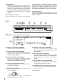
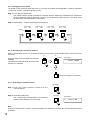
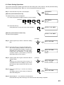
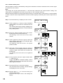
5.1.1. Selecting cameras for operation
Cameras to be manually controlled can be selected during full-screen or multi-segment screen display.
(Refer to p. 10 – 12 for individual camera operations.)
Step 1. Using the numerical keypad, press the
desired camera number.
Step 2. Press either the Full-Screen key or
Control key.
(Example)
1
3
FU LL
CONTROL
Lights
2-1. Operation in full-screen display
format
Press the Full-Screen key.
The Control indicator will light,
permitting operation of the designated
camera.
13
CONTROL
CONTROL
Lights
2-2. Operation in multi-screen display
format
Press the Control key during multiscreen display.
The Control indicator will light,
permitting operation of the designated
camera.
CHANNEL
LCD screen
13
CON T ROL
Monitor screen
(10-segment split-screen display)
This camera can be operated.
Note
Both XX and YY camera images can be freely
set using the switch.
LCD screen
Camera name
09
10
11
12
13
14
15
16
XX
YY
9
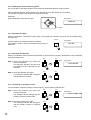
5.1.2. Rotating the camera with the joystick
Any connected Combination camera can be rotated in the desired direction using a joystick.
With the camera selected, tilt the joystick in the direction in which the camera is to be rotated.
The camera will rotate in the direction the joystick was tilted.
(Example)
When panning the camera to the right.
UP
LCD screen
MANUA L
LEFT
RIGHT
DOWN
Joystick
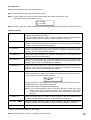
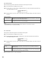
5.1.3. Activating the wiper
When a Combination camera with built-in wiper is connected to the system, the wiper can be activated using
the Wiper key.
WIPER
LCD screen
Press the Wiper key while the camera is selected.
The camera's built-in wiper is activated while the key is
held down.
WI PER
5.1.4. Activating the defroster
When a Combination camera with built-in defroster is connected to the system, the defroster can be activated
using the Defroster key.
DEF
DEF
Lights
Step 1. Press the Defroster key while the
camera is selected.
The defroster indicator will light and
the camera's built-in defroster will be
activated.
LCD screen
DE F ROS T ER
DEF
DEF
Lighting
Step 2. Press the Defroster key again.
The defroster indicator will extinguish
and the defroster will stop.
5.1.5. Controlling an auxiliary contact
The Combination camera's Auxiliary Contact Output 1 can be switched ON and OFF.
Step 1. Press the Auxiliary key while the
camera is selected.
The Auxiliary indicator will light and the
auxiliary contact is switched ON.
Step 2. Press the Auxiliary key again.
The Auxiliary indicator will extinguish
and the auxiliary contact is switched
OFF.
10
AUX
AUX
Lights
LCD screen
A U X I L I A R Y SW
AUX
AUX
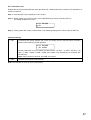
5.1.6. Activating the automatic functions
When a Combination camera is connected to the system, its automatic functions can be enabled using the
Auto key.
Step 1. Press the Auto key while the camera
is selected. The camera's automatic
functions (Auto-Pan*1, Auto Trace*2,
or Preset Sequence*3) will begin to
operate.
AUTO
AUTO
Lights
LCD screen
AUTO
Set the automatic functions to be enabled on the Camera Menu. (Refer to p. 40.)
*1 The camera's automatic panning function.
*2 Automatic repetition of manual camera operations that have been stored in memory.
*3 Automatic sequential display of camera positions in the order that their position numbers were
selected.
AUTO
AUTO
Lights
Step 2. Press the Auto key again.
The Auto indicator extinguishes and
automatic operations are stopped.
5.1.7. Activating the zoom function
When a Combination camera is connected, its zoom lens can be activated using the Zoom key.
Press the Zoom ("Telescope" or "Wide Angle") key while
the camera is selected. Zooming continues as long as the
key is pressed.
ZOOM
TELE
LCD screen
MANUA L
WIDE
5.1.8. Activating the focus function
When a Combination camera is connected, its image can be focused using the Focus key.
Press the Focus ("Far" or "Near") key while the camera is
selected. Focusing continues as long as the key is
pressed.
FOCUS
FAR
LCD screen
MANUA L
NEAR
11
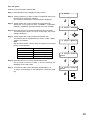
5.1.9. Changing the lens speed
The speed of lens movement when the Zoom or Focus key is pressed can be adjusted in 4 steps of operation:
1) Very slow, 2) Slow, 3) Moderately fast, 4) Fast.
Step 1. Press the Lens Speed key.
The speed indicator number increases by one each time the Speed key is depressed to indicate that
the lens speed has been increased by one level. (Lens operating speed returns to "Very slow" when
the Speed key is pressed while in Fast mode.)
Step 2. Repeat Step 1. until the desired speed is displayed.
LENS SPEED
LENS SPEED
LENS SPEED
LENS SPEED
LOW
LOW
LOW
LOW
HIGH
HIGH
HIGH
HIGH
Lights
5.1.10. Activating the auto-focus function
When a Combination camera is connected, the Auto-Focus function can be activated with a press of the AutoFocus key.
AF
AF
Lightis
Press the Auto-Focus key while the camera is
selected.
The indicator remains lit while the Auto-Focus
function is in operation.
LCD screen
AU TO FOCUS
AF
Auto-focus operation is completed.
5.1.11. Selecting the camera position
(Example)
Step 1. Enter the camera position number with the
numeric keypad.
Step 2. Press the Position key.
The camera image corresponding to the selected
position will be displayed on the monitor.
5
POSITION
LCD screen
5
POS I T I ON
Note
When the Trace function is used in the camera setting, the selection of Position No. 255 executes Auto-Trace
operations.
12
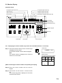
5.2. Monitor Display
[Operation keys]
16-segment split-screen key
10-segment split-screen key
Alarm hold key
9-segment split-screen key
Alarm reset key
Function key
4-segment split-screen key
A
B
C
Sequential 4-segment split-screen key
FUNCTION
D
E
ALARM
RESET HOLD
F
G
GROUP
SELECT SEQUENCE
H
CH
MENU
CH call key
Sequential key
Group selector key
WIPER
ZOOM
TELE
DEF
AUX AUTO
FOCUS
FAR
AF
FREEZE
LENS SPEED
LOW
HIGH
POSITION
FULL
UP
LEFT
WIDE
CONTROL
RIGHT
1
2
3
4
5
6
7
8
9
C
0
SET
Numeric keypad
SET key
NEAR
DOWN
REMOTE CONTROLLER C-RM500
Freeze key
Control key
Full-screen key
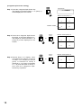
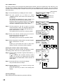
5.2.1. Displaying the camera number (only active when the Multi-Switcher is connected)
Step 1. Press the Channel Call key while a camera image
is displayed on the monitor.
All connected camera numbers will be displayed.
CH
Note
The camera number is displayed even when the
camera is not connected.
LCD screen
C H A N N EL
CAL L
Monitor screen
(10-segment split-screen display)
01
02
03
04
05
06
07
08
12
16
[When confirming the camera number and operating its display]
Step 2. Enter the camera number with the numeric
keypad.
Step 3. Press either the Full Screen or Freeze Screen
key.
The camera image will be displayed in full-screen
or freeze-screen format.
13
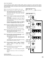
5.2.2. Viewing the freeze screen (only active when the Multi-Switcher is connected)
(Example)
Step 1. Enter the camera number to
freeze using the numeric
keypad.
Step 2. Press the Freeze Screen key.
The "F" indication will flash on
the corresponding camera
image screen.
1
3
FREEZE
FREEZE
Flashes
1 3 FREEZE
Step 3. Repeat Steps 1 and 2 to freeze
other camera images.
Note
In a system using the RS-232C to
control the Multi-Switcher, the freeze
screen display is only possible when the
full-screen mode is selected.
LCD screen
Monitor screen
(10-segment split-screen display)
09
10
11
12
F
14
15
16
Freeze display indication
Camera name
XX
FREEZE
Note: Two lower screens can be freely
set using the switcher.
[Simultaneously resetting all freeze displays]
Press the Freeze Screen key.
FREEZE
FREEZE
LCD screen
Monitor screen
(10-segment split-screen display)
09
10
11
12
13
14
15
16
[Resetting individual freeze displays]
XX
YY
(Example)
Step 1. Enter the camera number to reset the
freeze display using the numeric
keypad.
1
3
FREEZE
FREEZE
Step 2. Press the Freeze Screen key.
LCD screen
Monitor screen
(10-segment split-screen display)
The freeze display will be reset.
14
09
10
11
12
13
14
15
16
XX
FREEZE
5.2.3. Using the Function keys
By simply pressing a Function key (A – H), the camera image (camera number and position number)
programmed into the key can be displayed on the monitor. (Refer to p. 37 "Function key programming.")
Press a Function key (A – H).
The corresponding camera image (camera number and position number) is displayed on the full screen of the
monitor.
A
B
C
FUNCTION
D
E
CONTROL
F
G
Lights
H
LCD screen
D
F UNC T I ON KE Y
01
Display of the camera number programmed
into the Function key.
5.2.4. Using the abbreviated numbers
By merely pressing the abbreviated number followed by the SET key, the camera image (camera number and
position number) programmed under the abbreviated number can be displayed on the monitor.
(Refer to p. 38 "Abbreviation.")
Step 1. Enter the abbreviated number with the
numeric keypad.
2
5
CONTROL
Step 2. Press the SET key.
The programmed camera position's
image will be displayed on the full
screen. Simultaneously, the Control
indicator lights, permitting camera
operations with the joystick.
Lights
SET
LCD screen
25
SET
01
Display of the camera number programmed
under the abbreviated number.
15
5.2.5. Viewing full-screen displays
Step 1. Enter the camera number to be
displayed on the full screen using the
numeric keypad.
(Example)
1
3
FULL
CONTROL
Step 2. Press the Full Screen key.
The designated camera image will be
displayed on the full screen.
Simultaneously, the Control indicator
lights, permitting camera operations
with the joystick.
Lights
LCD screen
13
CHANNEL
13
Camera number displayed
in full-screen format
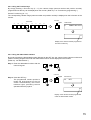
5.2.6. Viewing multi-screen displays (only active when the Multi-Switcher is connected)
[16-segment split-screen viewing]
Press the 16-Segment Split-Screen key.
All connected camera images will be displayed on the monitor.
LCD screen
1 6 – S E GME N T
Monitor screen
01
02
03
04
05
06
07
08
09
10
11
12
13
14
15
16
Camera number
16
[10-segment split-screen viewing]
LCD screen
Step 1. Press the 10-Segment Split-Screen key.
The images of camera numbers 1 – 8 (Group 1)
and 2 more images (set with the Switcher) will
be displayed on the monitor.
1 0 – S E GME N T
Monitor screen (Group 1)
Camera number
01
02
03
04
05
06
07
08
Camera name
XX
YY
Note: Camera images can be freely selected for
Screens XX and YY using the switcher.
Step 2. Press the 10-Segment Split-Screen key
again, or the Group Selector key.
The images of camera numbers 9 – 16
(Group 2) and 2 more images (set with
the Switcher) will be displayed on the
monitor.
GROUP
SELECT
or
Monitor screen (Group 2)
09
10
11
12
13
14
15
16
XX
YY
[9-segment split-screen viewing]
LCD screen
Step 1. Press the 9-Segment Split-Screen key.
The images of camera numbers 1 – 9 (Group 1)
will be displayed on the monitor.
9 – S E GME N T
Monitor screen (Group 1)
Camera number
Step 2. Press the 9-Segment Split-Screen key
again, or the Group Selector key.
The images of camera numbers 10 – 16
(Group 2) will be displayed on the
monitor.
GROUP
SELECT
or
01
02
03
04
05
06
07
08
09
Monitor screen (Group 2)
10
11
12
13
14
15
16
17
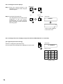
[4-segment split-screen viewing]
LCD screen
Step 1. Press the 4-Segment Split-Screen key.
The images of camera numbers 1 – 4 (Group 1)
will be displayed on the monitor.
4 – S E GME N T
Monitor screen (Group 1)
01
02
03
04
Camera number
Step 2. Press the 4-Segment Split-Screen
key again, or the Group Selector key.
The images of camera numbers 5 – 8
(Group 2) will be displayed on the
monitor.
GROUP
SELECT
or
GROUP
SELECT
Step 3. Repeat Step 2 to display other
succeeding the images of camera
numbers. The displayed camera
group is switched to Group 3
(Cameras 9 – 12), Group 4 (Cameras
13 – 16) and then back to Group 1
each time the 4-Segment SplitScreen key is pressed.
18
Monitor screen (Group 2)
05
06
07
08
Monitor screen (Group 3)
or
09
10
11
12
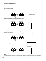
5.2.7. Viewing sequential displays
The outputs of all cameras connected to the switcher can be displayed on the monitor in sequential order at
viewing intervals preset at the switcher. For details, refer to the instruction manual included with the switcher.
[Sequential full-screen viewing]
SEQUENCE
Press the Sequence key. The
images for Cameras 1 – 16 are
displayed in sequential order.
Note that if the Tour Sequence
function has been set, the
camera images will be switched
in the order of the specified
reproduction number. Refer to
p. 39 "Tour sequence.")
LCD screen
S EQUENCE
Monitor screen
Camera No. 1
Note
In this example, Camera No. 2 is not
displayed on the monitor because it is
not connected.
Camera name
Camera No. 3
Camera name
Camera No. 16
Camera name
[Sequential 4-segment split-screen viewing]
Press the sequential
Segment Split-Screen key.
LCD screen
4-
4 – SEG SEQ
Tip
The Program Sequence
function is made operational
when the Smart Switcher is
connected. For details, refer to
the instruction manual included
with the Smart Switcher.
Monitor screen
Group 1
Camera name
Group 2
AAAA
BBBB
EEEE
FFFF
CCCC
DDDD
GGGG
HHHH
Group 4
Group 3
MMMM
NNNN
IIII
JJJJ
OOOO
PPPP
KKKK
LLLL
19
5.3. Alarm Hold and Reset
The Alarm can be held or reset when "1. KEY" has been selected in the "Alarm Hold" setting, and is not
activated when "2. ALWAYS" has been selected. (Refer to p. 36 "Alarm hold.")
5.3.1. Holding the alarm
Press the Alarm Hold key.
The Alarm Hold indicator light will flash.
RESET HOLD
RESET HOLD
Flashes
LCD screen
A L ARM HO L D
[When an alarm signal is received during Alarm Hold]
The Alarm Reset indicator light flashes while the "AL HOLD" indication is displayed on the monitor.
RESET HOLD
RESET HOLD
Flashes
Monitor screen
(4-segment split-screen display)
AL HOLD
01
02
03
04
5.3.2. Displaying alarm-activated camera images
Press the Alarm Hold key.
The Alarm Hold indicator light will extinguish, displaying the alerted camera image on the monitor in fullscreen format.
RESET HOLD
RESET HOLD
Monitor screen
ALARM
5.3.3. Resetting the alarm
Press the Alarm Reset key.
The Alarm Reset indicator light will extinguish, resetting the alarm state.
RESET HOLD
RESET HOLD
Monitor screen
01
02
03
04
Note
The alarm cannot be reset when "2. LEVEL" has been selected in the Alarm Signal setting. The state of alarm
continues as long as an alarm signal input is received. (Refer to p. 35 "Alarm signal.")
20
6. SETTINGS
6.1. Setting Items and Their Descriptions
Operation mode*
(Refer to p. 24)
Designates the unit as a master or slave.
Switcher*
(Refer to p. 25)
Determines the type of switcher to be connected to the unit.
Contact point
(Refer to p. 26)
Sets the Alarm Contact Output Terminal's operation.
(Only valid when "MASTER" has been selected in the "Option mode" setting.)
Automatic reset
(Refer to p. 27)
Sets the function to automatically return the camera to a specified (Home)
position after operation completion.
Home position
(Refer to p. 28)
Sets the Combination camera's standby status.
I/O speed*
(Refer to p. 29)
Sets the transfer rate of each control terminal.
Buzzer*
(Refer to p. 30)
Sets whether or not to sound a buzzer when an alarm is engaged.
Initial screen
(Refer to p. 30)
Sets the screen to be displayed on the monitor immediately after the
power is switched ON.
Channel designation
(Refer to p. 31)
Sets the channel (camera number) to be displayed first when the power is
switched ON.
Sensor alarm
(Refer to p. 32)
"ON" when using the Sensor Alarm function.
Camera alarm
(Refer to p. 32)
"ON" when using the Combination camera's alarm contact input.
Camera check
(Refer to p. 33)
Checks the Combination camera connected to the camera control terminal
for 30 seconds.
Camera alarm preset
(Refer to p. 34)
Sets the position number and direction in which the Combination camera
will automatically face when an alarm signal is received from the camera.
(Only valid when "ON" has been selected in the "Camera alarm" setting.)
Alarm signal
(Refer to p. 35)
Sets the type of alarm activation signal.
Alarm interval
(Refer to p. 35)
Sets the time interval from alarm signal reception to reset.
Alarm function
(Refer to p. 36)
Sets the monitor display method when an alarm signal is received.
(Only valid when "EDGE" has been selected in the "Alarm signal" setting.)
Alarm hold
(Refer to p. 36)
Sets the monitor display to be switched when an alarm signal is received.
Function key
(Refer to p. 37)
Displays the corresponding preset camera image (camera number and
position number) on the monitor.
Abbreviation
(Refer to p. 38)
Displays the corresponding preset camera image (camera number and
position number) on the monitor when the abbreviated number (entered
with the numeric keypad) is entered, followed by the SET key.
Tour sequence
(Refer to p. 39)
Sequentially displays two or more camera outputs on full screen in order of
reproduction (1 – 128) at preset time interval (seconds).
Camera menu
(Refer to p. 40)
Calls up the camera's built-in menu screen, permitting various
Combination camera settings, such as present position.
Password
(Refer to p. 40)
Sets the password required to open the menu.
* Can be set when "SLAVE" has been selected in the "Operation mode" setting. In this event, other items are
not displayed on the menu screen.
21
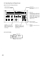
6.2. Operating Keys and Display Screen
[Keys to be used in setting operations]
Alarm Reset key
LCD screen
Used for password setting.
Displays the setting items and
their contents.
A
B
C
FUNCTION
D
E
ALARM
RESET HOLD
F
G
GROUP
SELECT SEQUENCE
H
CH
MENU
Menu key
WIPER
DEF
ZOOM
TELE
AUX AUTO
FOCUS
FAR
AF
FREEZE
LENS SPEED
LOW
HIGH
POSITION
FULL
UP
LEFT
WIDE
CONTROL
RIGHT
1
2
3
4
5
6
7
8
9
C
0
SET
Pressing this key calls up the
menu display on the LCD screen.
The menu display returns to the
normal screen if the key is
pressed again during setting
(except during "Camera menu"
and "Password" settings).
(Refer to p. 40.)
NEAR
DOWN
REMOTE CONTROLLER C-RM500
Numeric keypad
Used for entering numbers.
Joystick
Clear key
SET key
Selects setting items when
tilted up and down, and
setting contents when tilted
left and right.
Returns the mode to the
setting item selection without
confirming or changing the
setting contents.
Confirms the setting items and
contents.
[LCD screen display]
Setting item
O P E R A T I ON MOD E
1 . MA S T E R
Setting content
22
6.3. Basic Setting Operations
This section shows basic operating procedures for each setting item. Note, however, that the password setting
differs from those explained here. Refer to p. 40 for the password setting procedure.
MENU
Step 1. Press the Menu key with a pointed object.
P A S S WO R D
[When the password has been set]
The password entry screen is displayed.
1-1. Enter the password (4 digits) using the numeric keypad.
(Example)
1
2
3
P A S S WO R D
1234
4
1-2. Press the SET key.
If the password is correct, the menu screen appears.
O P E R A T I ON MOD E
SET
[When the password has not been set]
The menu screen appears.
O P E R A T I ON MOD E
(Example)
UP
Step 2. Tilt the joystick up or down to select the setting
item.
LEFT
RIGHT
AUTO RETURN
DOWN
Step 3. Press the SET key to confirm the setting item.
The current setting contents (if not set, the
factory-predetermined setting contents) are
displayed at the lower part of the LCD screen.
In this event, one character "1" of the setting
contents flashes. (The flashing character
differs depending on the content.)
Step 4. Tilt the joystick left or right to select the desired
setting content.
Tip
Pressing the Clear key before Step 4 is
completed will return the display to the screen
last shown (in Step 2) before the SET key was
pressed.
Step 5. Press the SET key to confirm the setting
contents.
The display returns to the screen (in Step 2) to
select the setting item.
AUTO RETURN
1 . ON
SET
Flashes
(Example)
UP
LEFT
RIGHT
AUTO RETURN
1 . ON 1 0 S EC
DOWN
(Step. 2)
SET
AUTO RETURN
Step 6. Repeat Steps 2 – 5 to continue to set other items.
Press the Menu key when returning to the normal screen after setting completion.
23
6.4. Setting the Functions
Perform the following settings referring to the Basic Setting Operations on p. 23.
6.4.1. Operation mode
Sets the unit's operation mode.
Step 1. Press the Menu key to display the menu screen.
Step 2. Tilt the joystick up or down to select "OPERATION MODE," and confirm it by pressing the SET key.
The setting contents will be displayed on Line 2.
O P E R A T I ON MOD E
1 . MA S T E R
Step 3. Tilt the joystick left or right to select either of the following setting contents and confirm it with the
SET key.
[Setting contents]
1. MASTER
Be sure to select Master when only a single C-RM500 unit is used.
When 2 units are connected, set either unit as the Master and the other as "SLAVE."
2. SLAVE
When 2 units are connected, set either unit as "SLAVE," and the other as "MASTER."
Note: Operation mode is set as "1. MASTER" by the factory.
24
6.4.2. Switchers
Sets the type of switcher to be connected to the unit.
Step 1. Press the Menu key to display the menu screen.
Step 2. Tilt the joystick up or down to select "SWITCHER" and confirm it with the SET key.
The setting contents will appear on Line 2.
SW I T C H E R
1 . 1 6 I NPUT
Step 3. Tilt the joystick left or right to select one the following setting contents and confirm it with the SET key.
[Setting contents]
1. 16 INPUT*1
Select this setting when the 16 channels Multi-Switcher is connected to the
switcher control terminal (RS-485).
Select this setting when the system includes a switcher other than Multi-Switcher
or Smart Switcher, and the number of control channels is 16 or less.
2. 9 INPUT A*1
Select this setting when the 9 channels Multi-Switcher is connected to the
switcher control terminal (RS-485) and Camera 9's 4-segment split-screen display
is set for "OFF" in the Multi-Switcher settings.
3. 9 INPUT B*1
Select this setting when the 9 channels Multi-Switcher is connected to the
switcher control terminal (RS-485) and Camera 9's 4-segment split-screen display
is set for "ON" in the Multi-Switcher settings.
4. 16 INPUT-2*1
Select this setting when the 16 channels Multi-Switcher is connected to the
switcher control terminal (RS-232C).
5. 9 INPUT A-2*1
Select this setting when the 9 channels Multi-Switcher is connected to the
switcher control terminal (RS-232C) and Camera 9's 4-segment split-screen
display is set for "OFF" in the Multi-Switcher settings.
6. 9 INPUT B-2*1
Select this setting when the 9 channels Multi-Switcher is connected to the
switcher control terminal (RS-232C) and Camera 9's 4-segment split-screen
display is set for "ON" in the Multi-Switcher settings.
7. SMART
Select this setting when a Smart Switcher is connected to the switcher control
terminal (RS-232C). Confirming this setting will cause the unit to wait for the entry
of the number of connected Smart Switchers.
SW I T C H E R
7 . SMAR T
1
Enter the number of Smart Switchers connected to the system. If the number has
already been set, the set number is displayed.
Confirm the number of switchers with the SET key.
Note: Up to 8 Smart Switchers can be connected. Be sure to enter the correct
number. If the wrong number is entered, such symptoms will occur that
unconnected cameras are selected or connected cameras cannot be
selected.
8. OTHER 16*2
9. OTHER 16
10. OTHER*2
Select this setting when the system includes a switcher other than Multi-Switcher
or Smart Switcher, and the number of control channels is 16 or less.
64*2
Select this setting when the system includes a switcher other than Multi-Switcher
or Smart Switcher, and the number of control channels is between 17 and 64.
Test mode
* Power synchronization cannot be chosen by setup menu of the camera in this setting.
*2 Camera alarm is unreceivable in this setting.
1
Note: The switcher type is set to "4. 16 INPUT-2" by the factory.
25
6.4.3. Contact
Sets the alarm contact output terminal's operation.
Note
Contacts can only be set when "MASTER" has been selected in the "Operation mode" setting. This setting
item is not displayed on the menu screen if "SLAVE" has been selected.
Step 1. Press the Menu key to display the menu screen.
Step 2. Tilt the joystick up or down to select "CONTACT" and confirm it with the SET key.
The setting content will appear on Line 2.
CON T AC T
1 . SELECT CH
Step 3. Tilt the joystick left or right to select one of the following setting contents, and confirm it with the
SET key.
[Setting contents]
1. SELECTION CHANNEL
Makes the contact corresponding to the channel number (camera number)
when each channel is selected for full-screen display.
Also, if the connection of a switcher with 16 or more input channels has
been set, the channel number selected for full-screen display is converted
into binary data, and contacts 1 – 16 are assigned bits 0 – 15.
2. ALARM
Makes the contact corresponding to the alarm-activated channel number
(camera number) when the number of connected switcher inputs is 16 or
less and there is an alarm signal input to each channel.
Also, if 16 or more inputs are set, the last channel to receive an alarm
signal is converted into binary data, and contacts 1 – 16 are assigned bits
0 – 15. In the normal state, no contacts are enabled.
3. BOTH
In the normal state, the contact corresponding to the channel number
(camera number) is made when each channel is selected for full-screen
display. In the alarm state, when an alarm signal is input, the contact
corresponding to the channel number is made.
Notes
• When "10. OTHER" has been selected in the "Switchers" settings, only "1. SELECTION CHANNEL" can be
set.
• This selection is set to "2. ALARM" by the factory.
26
6.4.4. Automatic reset
Enables the function that automatically resets the camera to a fixed position if the camera is not operated for a
preset time interval.
Step 1. Press the Menu key to display the menu screen.
Step 2. Tilt the joystick up or down to select "AUTO RETURN" and confirm it with the SET key.
The setting will appear on Line 2.
AUTO RETURN
1 . ON
Step 3. Tilt the joystick left or right to select either of the following settings and confirm it with the SET key.
[Setting contents]
1. ON
Confirming this setting displays the screen for setting the time interval before Automatic
Reset occurs following camera operation.
AUTO RETURN
1 . ON 1 0 S EC
Tilt the joystick left or right to select the reset interval: "10 SEC," "15 SEC," "20 SEC," "30
SEC," "1 MIN," "2 MIN," "3 MIN," "4 MIN" and "5 MIN." The selected time is confirmed with
the SET key.
Note: "SEC" stands for seconds, and "MIN" for minutes.
2. OFF
Disables the Automatic Reset function.
Note: This selection is set to "2. OFF" by the factory.
27
6.4.5. Home position
Sets the Combination camera to standby status when not being operated.
Note
When "10. OTHER" is selected in the "Switchers" setting, set the
operation common to all channels. In this event, the screen described
in Step 2 below and the rightmost [
CH] indication on the LCD
screen are not shown.
Step 1. Press the Menu key to display the menu screen.
Step 2. Tilt the joystick up or down to select "HOME POS," then
confirm it with the SET key.
The channel (camera number) input screen for the Home
Position setting will appear.
Step 3. Enter the channel number with the numeric keypad, and
confirm the entry with the SET key.
The operation setting is displayed on the bottom line, and the
cursor moves to the position "P" (left). The No. "1" on the left
shows the operation setting when the Home Position selection
input terminal in the unit's rear panel-mounted Alarm
output/control input terminal is broken. Similarly, the No. "2" on
the right shows the operation setting when the Home Position
terminal is made.
(Refer to p. 49 "Alarm Output/Control Input Terminal
Connections.")
Step 4. Tilt the joystick left or right to select the operation settings for
"1" from the list shown below.
Step 5. Press the SET key to confirm the operation setting for "1."
The cursor moves to "P" (right).
Step 6. Tilt the joystick left or right to select the operation settings for
"2" from the list shown below.
Step 7. Press the SET key to confirm the operation setting for "2."
The procedure returns to Step 3, and the settings are displayed
on the LCD screen.
HOME P O S
2
SET
HOME P O S
CH
(Example)
3
7
SET
HOME P O S
CH 7
1 POS 1
2 POS1
UP
4
LEFT
RIGHT
DOWN
HOME P O S
CH 7
1 T RACE 2 POS1
5
SET
HOME P O S
CH 7
1 T RACE 2 POS1
UP
6
LEFT
RIGHT
DOWN
Step 8. To further set other channels, repeat Steps 3 – 7.
To return to the setting display, press the Clear key.
[Home position selector terminal operation settings]
POS1
POS2
PAN
TRACE
P-SEQ
OFF
Orients the camera in the direction of Position 1, as set at the camera.
Orients the camera in the direction of Position 2, as set at the camera.
Activates the Auto-Pan function*1.
Activates the Auto Trace function*2.
Activates the Preset Sequence function*3.
HOME P O S
CH 7
1 TRACE 2 OF F
7
SET
*1 Automatically pans the camera pan/tilt head.
*2 Automatically executes manual camera operations stored in memory.
*3 Automatically sequences camera positions in the order that the position numbers were selected.
Notes
• Make sure to perform each camera setting when "POS2", "TRACE" or "P-SEQ." is selected. The unit could
malfunction if this setting is not correctly performed.
• This selection is set to "POS1" by the factory.
28
6.4.6. I/O speed
Sets each control terminal's transfer rate.
Step 1. Press the Menu key to display the menu screen.
Step 2. Tilt the joystick up or down to select "I/O SPEED" then press
the SET key to confirm the selection.
The screen for selecting the control terminal is displayed.
Step 3. Tilt the joystick left or right to select the control terminal.
Select the control terminal from "CAMERA," "SWCHER"
(switcher), "REMOTE" (Remote Control Unit), and "ALARM."
Step 4. Press the SET key to confirm the selected control terminal.
The transfer rate is shown on Line 2. In this event, the current
setting is displayed.
Step 5. Tilt the joystick left or right to select the transfer rate.
The transfer rate can be selected from "2400," "4800," "9600,"
"19200," and "38400."
Note
Set the same transfer rate as those of equipment connected
to each control terminal.
Control Terminal
Camera
Switcher
Remote control unit
Alarm
Factory Setting
38400 bps
19200 bps
19200 bps
38400 bps
I / O SPEED
2
SET
I / O S P E E D CAME RA
UP
3
LEFT
RIGHT
DOWN
I / O S P E E D R EMO T E
4
SET
I / O S P E E D R EMO T E
38400
UP
Step 6. Press the SET key to confirm the set transfer rate.
The procedure returns to Step 3, and the settings are
displayed on the LCD screen.
Step 7. To further set other control terminals, repeat Steps 3 – 6.
To return to the display of the setting item, press the Clear
key.
5
LEFT
RIGHT
DOWN
I / O S P E E D R EMO T E
19200
6
SET
29
6.4.7. Buzzer
Sets whether or not to sound the buzzer when an alarm signal is received.
Step 1. Press the Menu key to display the menu screen.
Step 2. Tilt the joystick up or down to select "BUZZER," then confirm the selection with the SET key.
The setting is displayed on Line 2.
BUZ ZER
1 . ON
Step 3. Tilt the joystick left or right to select either of the following settings, and confirm it with the SET key.
[Setting contents]
1. ON
Sounds a buzzer when alarm is activated.
2. OFF
Sounds no buzzer when alarm is activated.
Note: This selection is set to "1. ON" by the factory.
6.4.8. Initial screen
Sets the screen to be displayed immediately after the power is turned on.
Step 1. Press the Menu key to display the menu screen.
Step 2. Tilt the joystick up or down to select "INITIAL SCREEN," then confirm the selection with the SET key.
The setting will appear on Line 2.
I N I T I AL SCREEN
1 . FULL
Step 3. Tilt the joystick left or right to select one of the following settings, and confirm it with the SET key.
Note: The settings differ depending on the type of switcher connected to the system.
[Setting contents]
30
Switcher Type
Setting
Multi-Switcher
1. FULL (full screen)
2. SEQUENCE
3. 4-SEG SEQ (sequential 4-segment split-screen display)
4. 4-SEG (4-segment split-screen display)
5. 9-SEG
6. 10-SEG
7. 16-SEG
Notes
• Make sure that the selected setting is the same as that for the connected switcher.
• This selection is set to "3. 4-SEGMENT SEQ" by the factory.
Smart Switcher
1. FULL
2. SEQUENCE
Note: This selection is set to "SEQUENCE" by the factory.
Other switchers
1. FULL
6.4.9. Channel designation
Sets the first channel (camera number) to be displayed after the power is turned ON.
Note
This channel setting can only be performed when one of the settings "1. FULL," "4. 4-SEG," "5. 9-SEG," or "6.
10-SEG" has been selected in the "Initial screen" setting. The Channel Designation item is not displayed on
the menu screen when another setting has been selected.
Step 1. Press the Menu key to display the menu screen.
Step 2. Tilt the joystick up or down to select "INITIAL CHANNEL," then confirm the selection with the SET key.
The setting corresponding to the Initial Screen setting is displayed on Line 2.
Step 3. Using the joystick and numeric keypad, select the setting depending on the "Initial screen" setting,
and confirm the selected setting with the SET key. (Refer to the table shown below.)
[Setting contents]
"Initial screen" Setting
1. FULL
(full screen)
Setting
Enter the channel to be designated with the numeric keypad, and confirm
the setting with the SET key.
I N I T I AL CHANNEL
CHANNEL 1 2 3
Note: This selection is set to "1" by the factory.
4. 4-SEG
(4-segment split-screen
display)
Tilt the joystick to the left or right to select "1 – 4," "5 – 8," "9 – 12," or "13 –
16" and confirm with the SET key.
I N I T I AL CHANNEL
1 4
Note: This selection is set to "1 – 4" by the factory.
5. 9-SEG
(9-segment split-screen
display)
Tilt the joystick to the left or right to select "1 – 9" or "10 – 16," and confirm
with the SET key.
I N I T I AL CHANNEL
1 9
Note: This selection is set to "1 – 9" by the factory.
6. 10-SEG
(10-segment split-screen
display)
Tilt the joystick to the left or right to select "1 – 8" or "9 – 16," and confirm
with the SET key.
I N I T I AL CHANNEL
1 8
Notes
• Make sure that this setting is the same as that of the connected switcher.
• This selection is set to "1 – 8" by the factory.
31
6.4.10 Sensor alarm
Select "1. ON" to use the Sensor Alarm function.
Step 1. Press the Menu key to display the menu screen.
Step 2. Tilt the joystick up or down to select "SENSOR ALARM," and confirm the selection with the SET key.
The setting is displayed on Line 2.
S E N SOR A L ARM
1 . ON
Step 3. Tilt the joystick to the left or right to select either of the following settings, and confirm it with the
SET key.
[Setting contents]
1. ON
Uses Sensor Alarm.
2. OFF
Does not use Sensor Alarm.
Note: This selection is set to "1. ON" by the factory.
6.4.11. Camera alarm
Select "1. ON" to use the Combination camera's alarm contact input.
Step 1. Press the Menu key to display the menu screen.
Step 2. Tilt the joystick up or down to select "CAMERA ALARM," and confirm the selection with the SET key.
The setting is displayed on Line 2.
CAME RA A L ARM
1 . ON
Step 3. Tilt the joystick to the left or right to select either of the following settings, and confirm it with the
SET key.
[Setting contents]
1. ON
Uses the Combination camera's alarm contact input.
2. OFF
Does not use the Combination camera's alarm contact input.
Notes
• When operating the alarm by setting "Camera alarm" to "2. OFF," be sure to connect the optional C-AL80
Alarm Input Unit.
• This selection is set to "1. ON" by the factory.
32
6.4.12. Camera check
Checks Combination cameras connected to the camera control terminal for 30 seconds.
Note
Once the Camera Check has been completed, only the cameras connected when the check was made can be
controlled. Therefore, be sure to perform the camera check again whenever new cameras are added.
Step 1. Press the Menu key to display the menu screen.
Step 2. Tilt the joystick up or down to select "CAMERA CHECK," and confirm the selection with the SET key.
The check takes approximately 30 seconds. All keys are disabled during the check.
The check interval is counted down from 30 (seconds) displayed to the right of Line 1. The camera
numbers of the connected Combination cameras are displayed in numerical order on Line 2.
(Example)
CAME RA CH E CK
20
1 , 2 , 10 , 15 , 16 , 20
The indication "OK" is displayed after the 30-second check is completed.
CAME RA CH E CK
OK
1 , 2 , 10 , 15 , 16 , 20
After check completion, connected cameras can be confirmed by tilting the joystick to the left or right
to scroll the screen.
CAME RA CH E CK
OK
1 , 2 , 10 , 15 , 16 , 20
UP
LEFT
CAME RA CH E CK
30
UP
RIGHT
LEFT
OK
RIGHT
or
DOWN
DOWN
Step 3. Press the Clear key to return to the menu screen.
33
6.4.13. Camera alarm preset
Sets the position number to automatically change the Combination camera's orientation when an alarm signal
is received from the camera.
Note
This setting can only be performed when "1. ON" has been selected in the "Camera alarm" setting. This
setting item is not displayed on the menu screen when "2. OFF" has been selected.
Different camera positions can be programmed into each of 8 camera alarm contact inputs. It is also possible
to make a camera contact output that has received an alarm signal by interlocking the contact output with the
alarm.
Step 1. Press the Menu key to display the menu screen.
Step 2. Tilt the joystick up or down to select "PRESET
CAM ALARM," and confirm the selection with the
SET key.
The Camera Alarm Preset setting is displayed on
Line 2, and the unit switches to Camera Number
Entry Waiting mode.
Step 3. Enter the camera number using the numeric
keypad, and confirm with the SET key.
The flashing cursor will move to the alarm
number.
Step 4. Tilt the joystick to the left or right to select the
alarm number, and confirm the selected alarm
number with the SET key.
The flashing cursor will move to the preset
position number.
P R E S E T CAM A L ARM
2
SET
P R E S E T CAM A L ARM
CAM 1
AL1
123
(Example)
3
7
SET
P R E S E T CAM A L ARM
CAM 7
AL1
123
UP
4
LEFT
RIGHT
SET
DOWN
Step 5. Using the numeric keypad, enter the number of
the position to be displayed when the alarm
contact is made, and confirm the number with
the SET key.
The flashing cursor will move to the rightmost
position.
P R E S E T CAM A L ARM
CAM 7
AL5
123
Step 6. Tilt the joystick to the left or right to select either
[ ] (space) or [ ].
If [ ] is selected, the camera's auxiliary contact
output 2 can be set to be made when the camera
alarm signal is received.
P R E S E T CAM A L ARM
CAM 7
AL5
255
(Example)
5
2
5
UP
6
LEFT
RIGHT
DOWN
Step 7. Press the SET key to confirm the settings.
The procedure returns to Step 3, and the settings
are displayed on the LCD screen.
Step 8. Repeat Steps 3 – 7 to continue setting the
Camera Alarm Preset.
Press the Clear key to return to the setting item
display.
34
P R E S E T CAM A L ARM
CAM 7
AL5
255
7
SET
5
SET
6.4.14. Alarm signal
Sets continuous alarm operations.
Step 1. Press the Menu key to display the menu screen.
Step 2. Tilt the joystick up or down to select "ALARM SIGNAL," and confirm the selection with the SET key.
The setting is displayed on Line 2.
A L ARM S I GNA L
1 . EDGE
Step 3. Tilt the joystick to the left or right to select either of the following settings, and confirm it with the
SET key.
[Setting contents]
1. EDGE
Terminates alarm operations when the time interval set in the "Alarm time" setting (next
item) passes or when an alarm reset signal is received.
2. LEVEL
Terminates alarm operations when the alarm input terminal receives alarm end data. Also,
if "1. ON" has been selected in the "Camera alarm" setting, alarm operation will stop when
all alarm signals from the camera change from make to break data.
Note: This selection is set to "1. EDGE" by the factory.
6.4.15. Alarm time
Sets the interval between alarm input and alarm reset.
Note
The Alarm Time can only be set when "1. EDGE" has been selected in the "Alarm signal" setting. This setting
item is not displayed on the menu screen when "2. LEVEL" has been selected.
Step 1. Press the Menu key to display the menu screen.
Step 2. Tilt the joystick up or down to select "ALARM TIME," and confirm the selection with the SET key.
The setting is displayed on Line 2.
A L ARM T I ME
3 . 2 0SEC
Step 3. Tilt the joystick to the left or right to select one of the following settings, and confirm it with the SET key.
[Setting contents]
1. 10SEC
2. 15SEC
3. 20SEC
4. 30SEC
5. 1MIN
(10 seconds)
(15 seconds)
(20 seconds)
(30 seconds)
(1 minute)
6.
7.
8.
9.
10.
2MIN
3MIN
4MIN
5MIN
NO LIMIT
(2 minutes)
(3 minutes)
(4 minutes)
(5 minutes)
(no time limit)
Notes
• If "10. NO LIMIT" is selected, the alarm can only be reset when the Alarm Reset key on the unit's top panel
is pressed.
• This selection is set to "3. 20SEC" by the factory.
35
6.4.16. Alarm function
Sets the camera image monitor method to be used when an alarm signal is received.
Step 1. Press the Menu key to display the menu screen.
Step 2. Tilt the joystick up or down to select "ALARM FUNCTION," and confirm the selection with the SET key.
The setting will appear on Line 2.
A L ARM F UNC T I ON
1 . SEQ
Step 3. Tilt the joystick to the left or right to select either of the following settings, and confirm it with the
SET key.
[Setting contents]
1. SEQ (sequence)
Sequences the alarm-activated camera outputs to the monitor in full-screen
display in the order of alarm signal reception.
2. LAST
The output of the camera corresponding to the last received alarm signal is
displayed on the monitor in full-screen display.
Notes
• Only the selection "2. LAST" can be set when a Smart Switcher is connected to the system.
• This selection is set to "1. SEQ" by the factory.
6.4.17. Alarm hold
Always places on hold alarm signals to the surveillance camera system.
Step 1. Press the Menu key to display the menu screen.
Step 2. Tilt the joystick up or down to select "ALARM HOLD," and confirm the selection with the SET key.
The setting is displayed on Line 2.
A L ARM HO L D
1 . KEY
Step 3. Tilt the joystick to the left or right to select either of the following settings, and confirm it with the
SET key.
[Setting contents]
1. KEY
Permits the alarm to be held or reset using the unit's front panel-mounted keys.
(Refer to p. 20.)
2. ALWAYS
Always places the alarm on hold when an alarm signal is input.
Select this setting when it is not desirable to have the screen automatically
switched every time an alarm signal is received.
Note: This selection is set to "1. KEY" by the factory.
36
6.4.18. Function key programming
By simply pressing the function key, the camera image (camera number and position number) can be
displayed on the monitor. It is also possible to control alarm contact switching and instruct the camera to
perform multiple automatic operations.
Step 1. Press the Menu key to display the menu screen.
Step 2. Tilt the joystick up or down to select "FUNCTION
KEY" and confirm the selection with the SET key.
The settings is displayed on Line 2, and the unit
switches to Function Key Entry Waiting mode.
Note that when the camera number or the position
number is not programmed in advance, the "
"
indication is displayed in place of the number.
F UNC T I ON KE Y
CAM
POS
Position No.
Camera No.
F UNC T I ON KE Y
CAM
POS
Step 5. Enter the position number with the numeric keypad.
Enter a number from 1 to 255.
Tip
Entering "0" will switch the screen to full-screen
display, and will not execute position playback.
Step 6. Press the SET key to confirm the entered position
number.
The procedure returns to Step 3, and the set
contents are displayed on the LCD screen.
3
LEFT
RIGHT
SET
DOWN
F UNC T I ON KE Y
CAM
POS
A
(Example)
4
1
F UNC T I ON KE Y
CAM 1 5
POS
5
SET
A
(Example)
5
1
F UNC T I ON KE Y
CAM 1 5 POS 1 2 3
Step 7. Repeat Steps 3 – 6 to continue to set other Function
keys.
Press the Clear key to return to the setting item
display.
[Automatic operation settings]
After performing the settings in Steps 1 – 3 above, tilt the joystick up
or down to select one of the following settings, then press the SET key
to confirm it.
AUTO PAN
AUTO TRACE
PRESET SEQUENCE
AUX2 (auxiliary2)
A
UP
Step 3. Tilt the joystick to the left or right to select the
desired function key and confirm the setting with the
SET key.
The flashing cursor moves to the camera number.
Step 4. Enter the camera number using the numeric
keypad, and confirm it with the SET key.
Enter a number from 1 to 999.
The flashing cursor moves to the position number.
Function key
(A – H)
A
6
2
3
A
SET
F UNC T I ON KE Y
AUTO PAN
A
Continues panning between 2 points set on the camera menu.
Repeats manual operations set on the camera menu.
Plays back the positions stored in the camera in setting order.
Makes or breaks the Combination camera's auxiliary contact output #2.
[Deleting settings]
After pressing the Alarm Reset key, press the SET key.
37
6.4.19. Abbreviation
By merely pressing the preprogrammed abbreviated number (numeric keypad entry and SET key), the
camera image (camera number and position number) can be displayed on the monitor. Up to 512 camera
numbers or 512 camera/position numbers can be set. (The abbreviated number provides the same function as
the function key.)
Step 1. Press the Menu key to display the menu screen.
Step 2. Tilt the joystick up or down to select
"ABBREVIATION," and confirm the selection with
the SET key.
The settings are displayed on Line 2, and the unit
switched to Function Key Entry Waiting mode.
Note that when the camera number or the position
number is not programmed in advance, the "
"
indication is displayed in place of the number.
Abbreviated No.
(1 – 512)
ABBRE V I A T I ON
CAM
POS
Position No.
Camera No.
ABBRE V I A T I ON
CAM
POS
(Example)
Step 3. Tilt the joystick to the left or right, or use the
numeric keypad to enter the designed abbreviated
number and confirm the setting with the SET key.
Enter a number from 1 – 512.
The flashing cursor moves to the camera number.
Step 4. Enter the camera number using the numeric
keypad, and confirm with the SET key.
Enter a number from 1 to 999.
The flashing cursor moves to the position number.
Step 5. Enter the position number with the numeric keypad.
Enter a number from 1 to 255.
Tip
Entering "0" will switch the screen to full-screen
display, and will not execute position playback.
[Setting the camera's alarm contact output]
After confirming the camera number and position number,
the flashing cursor will move to the rightmost position.
Step 6. Tilt the joystick to the left or right to select either [ ]
(space) or [ ].
If [ ] is selected, the camera's auxiliary contact
output 2 can be set to be made when the camera
designed with the abbreviated number receives an
alarm signal.
Step 7. Press the SET key to confirm the settings.
The procedure returns to Step 3.
Step 8. Repeat Steps 3 – 6 to continue setting other
abbreviated numbers.
Press the Clear key to return to the setting item
display.
[Deleting Settings]
After pressing the Alarm Reset key, press the SET key.
38
3
1
8
ABBRE V I A T I ON
CAM
POS
SET
18
(Example)
4
2
8
ABBRE V I A T I ON
CAM 2 8
POS
SET
18
(Example)
5
1
1
ABBRE V I A T I ON
18
CAM 2 8
POS 1 1 6
UP
6
LEFT
RIGHT
DOWN
ABBRE V I A T I ON
18
CAM 2 8
POS 1 1 6
7
SET
6
SET
6.4.20. Tour sequence
The Tour Sequence function switches multiple camera outputs in sequence at a set time interval. Merely
pressing the Sequence key permits up to 128 camera outputs to be displayed on the full screen in the order of
their set playback number. The camera number, position number and viewing time can be set for individual
playback numbers.
Step 1. Press the Menu key to display the menu screen.
TOUR S EQ NO
(Set by the factory)
Step 2. Tilt the joystick up or down to select "TOUR SEQ"
and confirm the selection with the SET key.
The unit will wait for the entry of "YES" (to use the
function) or "NO" (to not use the function).
(Set by the factory)
Step 3. Tilt the joystick to the left or right to select either
"YES" or "NO," and confirm the entry by pressing
the SET key.
The setting is displayed on Line 2 if "YES" is
selected, and the unit switched to Playback Number
Entry Waiting mode.
Note that when the camera number or the position
number is not programmed in advance, the "
"
indication is displayed in place of the number.
Step 4. Enter the playback number using the numeric
keypad or by tilting the joystick to the left or right,
and confirm the entered number with the SET key.
Enter a number from 1 to 128.
The flashing cursor moves to the camera number.
TOUR S EQ Y E S
(Example)
3
SET
No.
TOUR S EQ
C
P
1
T 1 0SEC
(Example)
4
UP
LEFT
SET
3
SET
0
SET
or
DOWN
TOUR S EQ
C
P
1
RIGHT
1
T 1 0SEC
(Example)
Step 5. Enter the camera number with the numeric keypad,
and confirm the number with the SET key.
Enter a number from 1 to 999.
The flashing cursor moves to the position number.
Step 6. Enter the position number with the numeric keypad,
and confirm the number with the SET key.
Enter a number from 1 to 255.
Tip: Entering "0" will switch the screen to fullscreen display, and does not execute position
playback.
The flashing cursor moves to the rightmost viewing
interval selection indication on Line 2.
Step 7. Tilt the joystick to the left or right to select the
viewing interval: "3SEC," "10SEC," "15SEC,"
"20SEC," "30SEC," or "1MIN." (SEC: seconds,
MIN: minutes)
Step 8. Press the SET key to confirm the set interval.
The procedure returns to Step 4.
Step 9. Repeat Steps 4 – 8 to continue setting the playback
numbers.
Press the Clear key to return to the setting item
display.
5
1
TOUR S EQ
C123 P
2
1
T 1 0SEC
(Example)
6
2
0
TOUR S EQ
1
C1 2 3 P2 0 0 T 1 0SEC
UP
7
LEFT
RIGHT
DOWN
TOUR S EQ
1
C1 2 3 P2 0 0 T 1 0SEC
8
SET
[Deleting Settings]
After pressing the Alarm Reset key, press the SET key.
39
6.4.21. Camera menu
Calls up the camera's menu screen, and performs various Combination camera settings, such as the storage
of preset camera positions. For detailed operations and settings of the camera menu, refer to the instruction
manual included with the camera.
Step 1. Press the Menu key to display the menu screen.
Step 2. Tilt the joystick up or down to select "CAMERA MENU," and confirm the selection with the SET key.
The unit will wait for entry of the camera number that starts up the menu.
CAME RA ME NU
CH
Step 3. Enter the camera number with the numeric keypad, and confirm the entered number with the SET key.
The selected camera menu appears on the monitor.
Pressing the Menu key again while the menu is being displayed on the monitor will turn off the
display, returning the display to the camera number entry screen.
Step 4. Repeat Steps 2 and 3 to continue to set other camera numbers.
Press the Clear key to return to the setting item display.
6.4.22. Password
Sets the password required when opening the menu.
Step 1. Press the Menu key while holding down the Alarm Reset key.
The password setting screen will appear.
P A S S WO R D
Step 2. Enter the password (4 digits) with the numeric keypad, and confirm the password with the SET key.
The display will return to the normal screen.
40
7. CONNECTIONS
Note
To eliminate noise, be sure to connect the shield of a shielded twisted-pair cable to be used for connection
between control terminals (for control) to the [GND] terminal.
Equipment Which Can Be Controlled with the C-RM500
Shown below are equipment that can be controlled with the C-RM500.
Camera: C-CC501, C-CC504, C-CC551, and C-CC554
Up to 31 cameras can be connected to the unit's Camera control terminal and controlled. The use
of the C-IF500 Interface Unit will increase the number to up to 64 cameras (when the C-SS8
switcher is in use). Note that the cameras cannot be controlled if their number is greater than the
number of inputs of a connected switcher.
Switcher: C-MS90D, C-MS90S, C-MS160D, C-MS160S, and C-SS8
Only one switcher can be connected for remote camera control. However, as to the C-SS8, 1
master-designated unit and up to 7 slave-designated units can be connected to remotely control
the cameras.
About the Camera Control Terminal
The Camera control terminal is used to connect the C-CC501, C-CC504, C-CC551, or C-CC554 Combination
Camera or the C-IF500 Interface Unit. Up to 31 pieces of equipment can be connected to the terminal.
7.1. System Examples
[Example 1]
Combination camera
C-RM500
Monitor TV
41
[Example 2]
Combination camera
Multi-switcher
Monitor TV
C-RM500
Alarm input unit
Combination camera
[Example 3]
Combination camera
Smart switcher
Monitor TV
C-RM500
Alarm input unit
Combination camera
42
7.2. Connection to Combination Cameras
Connect the Combination camera's control cable to the unit's Camera Control terminal, making sure to match
their polarities.
C-RM500 (Operation mode: "MASTER")
Camera control terminal
GND
Shielded twisted-pair cable
Video output cable
A
1
B
A
B
2
3
4
5
Monitor TV
Camera control cable
Combination camera
[Connection cables]
• Recommended cable type: CPEV-S type (shielded twisted-pair cable) thicker than 0.65 mm in diameter.
• The maximum cable distance between the unit and the Combination camera is 1.2 km when connected in a
matched pair. If multiple cameras are connected to a system, the maximum distance between connected
equipment is 1.2 km in total.
Remote Controller
C-RM500
Combination
camera
a
Combination
camera
b
Combination
camera
c
a + b + c < 1.2 km
[Connected Camera Termination Switch Setting]
Make sure that the termination switches of the cameras connected to the system are set as follows.
Cameras other than the last connected camera: Termination switch OFF
Last connected camera:
Termination switch ON
Remote Controller
C-RM500
Combination
camera
Combination
camera
Combination
camera
Terminal switch
OFF
Terminal switch
OFF
Terminal switch
ON
43
7.3. Connection to the Multi-Switcher's RS-232C Terminal
• When connecting the camera's video output cable to the Multi-Switcher, match the Multi-Switcher's camera
input terminal number with the camera's address number.
• The C-CC551 and C-CC554 Combination cameras permit settings of up to 255 camera positions (camera
orientation), and the C-CC501 and C-CC504 permit settings of up to 64 positions. All are equipped with 8
alarm input terminals. To expand the alarm input, connect the C-AL80 Alarm Input Unit to the C-RM500
Remote Controller.
• To switch the display to the fixed camera output when an alarm signal is received, connect a sensor to the
switcher's alarm input terminal that corresponds to the video input number the fixed camera is connected to.
44
RS-232C reverse cable
Female D-sub 9-pin connector to Female D-sub 9-pin connector
C-RM500
Camera control terminal
Switcher control terminal
RS-232C
GND
Alarm output terminal
*
Fixed camera
A
Shielded twisted-pair cable
B
Multi-switcher
IN
IN
1
2
3
4
5
6
7
8
9
10
11
12
13
14
15
16
Alarm I/O
Camera input/output
RS-232C
1
2
2
Monitor output
*
Corresponding to
the fixed camera A
A
1
B
2
A
3
B
4
1
Camera control
cable
Alarm input
cable
4
6
5
Corresponding to
the fixed camera B
9
5, 10
Combination camera
1
1
2
3
Sensor
Sensor
Camera control
cable
4
Alarm input
cable
Monitor TV
4
6
5
9
Combination camera
5, 10
Sensor
The use of each camera's alarm input permits
connection of 8 sensors for each camera.
* Connect this cable only when "2. LEVEL" is selected in the unit's "Alarm signal" setting. (Refer to p. 35.)
Connect the C-RM500's alarm output corresponding to the Combination Camera address to the MultiSwitcher's alarm input, while leaving other output terminals not corresponding to any Camera address
unconnected.
45
7.4. Connection to the Smart Switcher's RS-232C Terminal
• When connecting the camera's video output cable to the Multi-Switcher, match the Multi-Switcher's camera
input terminal number with the camera's address number.
• The C-CC551 and C-CC554 Combination cameras permit settings of up to 255 camera positions (camera
orientation), and the C-CC501 and C-CC504 permit settings of up to 64 positions. All are equipped with 8
alarm input terminals. To expand the alarm input, connect the C-AL80 Alarm Input Unit to the C-RM500
Remote Controller.
Note
Do not use the Smart Switcher's Alarm input terminal as the unit could malfunction.
• To switch the display to the fixed camera output when an alarm signal is received, connect the Alarm Input
Unit to the unit. Also, in the unit's abbreviated number setting, set the position number of the fixed camera to
be switched to when an alarm signal is received to "0".
• The Alarm Input Unit activates the alarm for the abbreviated number. For details, refer to the section
"Abbreviation" on p. 38 in this manual, and the instruction manual included with the Alarm Input Unit.
46
C-RM500
Camera control terminal
Switcher control terminal
RS-232C
GND
Alarm input terminal
RS-232C
RS-232C reverse cable
Female D-sub 9-pin connector to Female D-sub 9-pin connector
Fixed camera
RS-232C reverse cable
Female D-sub 9-pin connector to
Female D-sub 9-pin connector
Shielded twisted-pair cable
Smart switcher
MONITOR
(SP/SQ)
1
2
3
4
5
6
7
8
IN
VIDEO
VIDEO
OUT
RS-232C
A
1
B
2
A
3
B
4
1
Camera control
cable
Alarm input
cable
4
6
5
9
5, 10
Combination camera
1
1
2
3
Sensor
Camera control
cable
Alarm input
cable
Monitor TV
4
6
4
5
9
5, 10
Sensor
Combination camera
The use of each camera's alarm input permits
connection of 8 sensors for each camera.
Sensor
Alarm input unit
C-AL80
ALARM/REMOTE IN
RS-232C
47
7.5. Connection When Controlling the System from 2 Locations
By connecting 2 C-RM500 Remote Controllers, the system can be controlled from 2 locations.
Set the operation mode of one controller for "MASTER," and the other controller for "SLAVE." (Refer to p. 24
"Operation mode".)
Note
Set the "I/O SPEED: REMOTE" of the MASTERdesignated C-RM500 Controller and "I/O SPEED:
SWITCHER" of the SLAVE-designated C-RM500
Controller to the same transfer rate. (Refer to p. 29
"I/O SPEED.")
(Example)
C-RM500 (MASTER)
C-RM500 (SLAVE)
I/O SPEED: REMOTE
9600 bps
I/O SPEED: SWITCHER
9600 bps
C-RM500 (Operation mode: MASTER)
Slave unit remote control terminal
GND
Shielded twisted-pair cable
C-RM500 (Operation mode: SLAVE)
GND
Switcher control terminal
48
7.6. Alarm Output/Control Input Terminal Connections
7.6.1. Pin functions
Shown below are the numbers and names of the Alarm I/O terminal pins.
C-RM500
Alarm output / control input terminal
13
1
14
25
Pin No.
1
2
3
4
5
6
7
8
9
10
11
12
13
Function
Ground
Alarm Output 1
Alarm Output 2
Alarm Output 3
Ground
Alarm Output 4
Alarm Output 5
Alarm Output 6
Ground
Alarm Output 7
Alarm Output 8
Alarm Output 9
Ground
Pin No.
14
15
16
17
18
19
20
21
22
23
24
25
Function
Alarm Output 10
Alarm Output 11
Alarm Output 12
Ground
Alarm Output 13
Alarm Output 14
Alarm Output 15
Alarm Output 16
Alarm Output
Alarm Input
Home Position Selection Input
Auxiliary Input
[Alarm Output Terminal] (Pin No. 1 – 16)
The terminal of the number corresponding to the alarm-activated camera number shorts with the ground
terminal. Alarm output terminals 1 – 16 are the NPN open collector output.
Operating current: Maximum 20 V, 20 mA
[Alarm Output Terminal] (Pin No. 22)
This terminal is shorted with the ground terminal even when only one of the alarm input terminals receives an
alarm signal. The alarm output terminal is the NPN open collector output.
Operating current: Maximum 20 V, 20 mA
[Alarm Input Terminal] (Pin No. 23)
Shorting this terminal with the ground terminal when "OTHER16," "OTHER16-64" or "OTHER" has been
selected in the "SWITCHER" setting will sound a buzzer and cause the Alarm Reset indicator to flash while it
is shorted. (Refer to p. 25 "Switchers.")
Open voltage: 5 V DC, short-circuit current: Maximum 5 mA
[Home Position Selection Input Terminal] (Pin No. 24)
When Auto-Return is performed while this terminal is being shorted to the ground terminal, the camera's
operation follows the setting made for "2" in the "Home position" setting. (Refer to p. 28 "Home position.")
Open voltage: 5 V DC, short-circuit current: Maximum 5 mA
[Auxiliary Input] (Pin No. 25)
Leave this input unconnected.
Open voltage: 5 V DC, short-circuit current: Maximum 5 mA
49
7.6.2. Assembling D-sub connectors onto cables
Prepare the D-sub connector supplied with the Unit.
Step 1. Solder the cable wires to the
corresponding connector pins to
be used.
Step 2. Bend back the braided shield and
wrap with the copper foil tape.
Shield cover B
7
Ring stopper
Lock screw
4
Hook
Step 3. Cover the connector with shield
cover A.
Nut
6
5
1
2
Step 4. Align shield cover B with shield
cover A, and press till its hook fits
into place.
Copper foil tape
Shield cover A
Step 5. Tighten the nut.
Step 6. Install the lock screws.
Step 7. Mount the ring stopper to the
screws.
50
3
8. SPECIFICATIONS
Power Source
Current Consumption
Slave Remote Controller
Camera Control
Switcher Control
Alarm Input
Alarm Output / Control Input
Display
Alarm Signal
Number of Unit Connections
Maximum Cable Distance
Operating Temperature
Operating Humidity
Finish
Dimensions
Weight
12 V DC (AC adapter)
150 mA
RS-485, screwless connector
RS-485, screwless connector
RS-485, screwless connector
RS-232C, D-sub connector (9 pins, male)
RS-232C, D-sub connector (9 pins, male)
Alarm output: 16 channels, NPN open collector output,
withstand voltage: 30 V DC, control current: 20 mA
Alarm input: 1 channel, no-voltage make contact input,
open coltage: 5 V DC, short-circuit current: 5 mA max.
Home position selection input: 1 channel, no-voltage make contact input,
open voltage: 5 V DC,
short-circuit current: 5 mA max.
D-sub connector (25 pins, female)
LED indication of control status, alarm status, alarm hold status,
still picture status, defroster, auxiliary setting, auto panning, and lens speed
LCD indication of key entry confirmation
Continuous alarm tone (can be turned on and off)
Up to 2 (one to be set for MASTER unit, another for SLAVE unit)
1.2 km* (between the Remote controller and the Combination cameras)
0 to +50°C
Under 90% (no due condensation produced)
Panel: Surface-treated steel plate, sand gray, paint
Sides: Rubber
326 (w) x 62 (h) x 185.2 (d) mm
1.8 kg (AC adapter excluded)
* Applies to the system where the unit and Combination camera are connected in a matched pair. Represents
the total of connected cable distances if multiple Combination cameras or Interface units are connected in
the system (when the CPEV-S cable thicker than 0.65 mm in diameter is used).
Note: The design and specifications are subject to change without notice for improvement.
• Accessories
D-sub connector (9 pins, male) .................. 1
D-sub connector (25 pins, male) ................ 1
C-RM500 complies with Part 15 of the FCC Rules.
Note
This equipment has been tested and found to comply with the limits for a Class A digital device,
pursuant to Part 15 of the FCC Rules. These limits are designed to provide reasonable protection
against harmful interference when the equipment is operated in a commercial environment. This
equipment generates, uses, and can radiate radio frequency energy and, if not installed and used in
accordance with the instruction manual, may cause harmful interference to radio communications.
Operation of this equipment in a residential area is likely to cause harmful interference in which case the
user will be required to correct the interference at his own expense.
Modifications
Any modifications made to this device that are not approved by TOA Corporation may void the authority
granted to the user by the FCC to operate this equipment.
51
Printed in Japan
133-12-743-6E