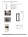
1
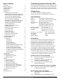
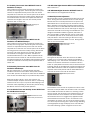
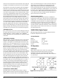
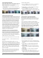
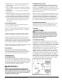
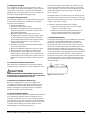
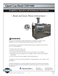
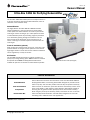
Issue 01
TM
LLC
Owners Manual
Ultra-Aire 135H Air Purifying Dehumidifier
FILTRATION
The Ultra-Aire 135H dehumidifier performs multiple functions in
a compact enclosure; high-capacity dehumidification, fresh air
ventilation, and is filtration ready.
Dehumidification
The highly efficient Ultra-Aire APD UA-135H dehumidifier
utilizes refrigeration to cool the incoming air stream below
its dew point. This cooled and drier air is used to pre-cool the
incoming air stream resulting in up to a 200 percent increase
in overall efficiency. After the pre-cooling stage the processed
air is reheated by passing through the condenser coil. The
heat removed by the evaporator coil is returned to the air
stream, resulting in an overall temperature increase from the
incoming air.
Fresh Air Ventilation (optional)
Fresh outdoor air is ducted to the unit via a 6” round duct. This
provides desired air changes to dilute pollutants and maintain
high oxygen content in the air. The amount of fresh air ventilation
can be regulated by a variety of controls.
Air Filtration
The UA-135H includes air filtration to improve the indoor air
quality of your living/working space. MERV-8 media is standard.
An optional second MERV-14 deep pleated media filter is
available for optimum air filtration to reduce airborne particles.
Figure 1: Ultra-Aire 135H (Package D)
Features and Benefits
Dehumidification
Fresh Air Ventilation
Compact Size
Remote Filter Box
Therma-Stor LLC announces the introduction of the Ultra-Aire Model 135H Air
Purifying Dehumidifier, a ventilating dehumidifier designed to provide ultimate
indoor air quality. The Ultra-Aire provides the three key components of healthy
indoor air: fresh air ventilation, particulate filtration and humidity control. At the
heart of the 135H is a high capacity, energy efficient dehumidifier capable of
removing over 17 gallons of water per day (at 80°F, 60% relative humidity).
while using only 12 amps of electricity (120V). This allows the unit to maintain
indoor humidity levels below 50%, the level widely recognized as critical for
controlling mold, mildew and dust mite populations.
Figure 2: Features and Benefits
© Copyright Therma-Stor LLC
1
Table of Contents
Introduction
Features & Benefits
1. Intended Application
2. Registrations
3. Specifications
4. Operation
4.1 Humidity/Fan Control Panel
WITHOUT Fresh Air Ventilation or Damper
4.1A Humidity/Fan Control Panel WITH Fresh
Air Ventilation and WITHOUT Damper
4.1B Humidity/Fan Control Panel WITH
Fresh Air Ventilation AND Damper
4.1C Ventilation Timer and Humidity Control
WITH Fresh Air AND Motorized Damper
4.1D DEH 2000 Digital Controller WITH
Fresh Air AND Damper
4.1E DEH 2000 Digital COntroller
WITHOUT Fresh Air
4.2 Humidity Control Adjustment
4.3 Fan/Filter Switch
4.4 Ventilation Timer
4.5 Setting the Time
4.6 Ventilation Schedule
4.7 Automatic or Manual Mode
4.8 Low Pressure Control
5. DEH 2000 Digital Control
5.1 Specifications
5.2 Operation
5.2A Display
5.2B Setting
5.2C On/Off Setting
5.2D Setting Clock Time
5.2E Setting Relative Humidity Setpoint
5.2F Fan Setting and Operation
5.2G Fan On Fan Off Fan Program
5.2H Damper Operation and Setting
5.2I Intermittent/Programmed Ventilation
5.2J Programming Notes
5.2K Stop Start
6. Maintenance
6.1 Standard Air Filter
6.2 High Efficiency Air Filter
6.3 Fresh Air Return
7. Service
7.1 Technical description
7.2 Troubleshooting
7.3 Refrigerant Charging
7.4 Impeller Fan Replacement
7.5 Compressor/Capacitor Replacement
7.6 Replacing Compressor - Nonburn Out
7.7 Electric Ventilation Damper
7.8 Condensate Pump Kit
8. Warranty
9. Optional Parts List
2
1 Intended Application for Ultra-Aire 135H
1
1
2
2
2
2
3
For the ideal installation, draw air from the central part of the
home and return it to isolated areas of the home like the bedrooms, den, utility room, or family room. The ductwork of the
existing heating system can be used to supply air to the home.
2 Registrations
The Ultra-Aire 135H (P/N 4025080) conforms to
UL STD 1995. Certified to CAN/CSA STD C22.2 No. 236.
3
3 Specifications
3
Model:
Electrical:
Capacity:
Operating Temp.:
Air Flow:
3
3
3
3
3
4
4
4
4
4
4
4
4
5
5
5
5
6
6
6
6
7
7
7
7
7
7
7
7
8
9
9
9
9
9
9
10
11
UA-135H Air Purifying Dehumidifier
110-120 VAC, 12 Amps, 60 Hz, grounded
135 pints/day @ 80°F, 60% RH
55°F min., 100°F max.
355 CFM without external ducting
335 CFM @ .20 IWG external static
315 CFM @ .40 IWG external static
Refrigerant Charge:
1 lb., 12 oz. R22
Duct Connections:
Round 10" inlet, 10" outlet
Filter Size:
Pleated cloth: 2" X 20" X 24"
High Efficiency: 4" X 20" X 24"
Unit Size (w/o duct collars):
31"L x 21"W x 18.65"H
Shipping Size:
37”L x 25”W x 28.5”H
Unit Weight:
100 lb.
Shipping Weight:
138 lb.
4 Operation
The Ultra-Aire UA-135H Air Purifying Dehumidifier performs
three functions in one compact enclosure; High-Capacity
Dehumidification, Fresh Air Ventilation, and Filtration. The
UA-135H can be equipped with various accessories to
enhance its operation. A remote control panel must be
used with the UA-135H. Your unit has one of three remote
control panels. To determine how each control operates
the UA-135H it must first be determined which control is
being used and whether or not the 135H is ducted for fresh
air ventilation. Refer to Section 7 to identify which control
you have installed. Inspect ducting or contact your installer
to determine if your UA-135H is ducted for outside air.
Humidity/Fan Control Panel (P/N 4024155)
4.1
Humidity/Fan Control Panel WITHOUT Fresh Air
Ventilation or Damper
4.1A
Humidity/Fan Control Panel WITH Fresh Air
Ventilation and WITHOUT Damper
4.1B
Humidity/Fan Control Panel WITH Fresh Air
Ventilation AND Damper
Ventilation Timer/Humidity Control Panel (P/N 4024125)
4.1C
Ventilation Timer and Humidity Control WITH Fresh
Air AND Motorized Damper
DEH 2000 Digital Control (P/N 4024539)
4.2
DEH 2000 Digital Controller WITH Fresh Air
AND Damper
4.2A
DEH 2000 Digital Controller WITHOUT Fresh Air
Ultra-Aire 135H Air Purifying Dehumidifier Owners Manual
4.1 Humidity/Fan Control Panel WITHOUT Fresh Air
Ventilation or Damper
The humidity/fan control panel automatically controls the
humidity of the living space. The humidity/fan control panel
contains an adjustable humidity control and a fan switch.
The panel has a cover that must remain open to the air within
the living space for accurate humidity sensing. Position the
fan switch ON when the home is occupied. This filters and
circulates air throughout the home. For humidity control
operation refer to section 4.2.
Figure 1: Humidity/Fan
Control Panel
4.1A Humidity/Fan Control Panel WITH Fresh Air
Ventilation and WITHOUT Damper
The humidity/fan control panel automatically controls the
humidity of the living space. The humidity/fan control panel
contains an adjustable humidity control and a fan switch.
The panel has a cover that must remain open to the air within
the living space for accurate humidity sensing. Position the
fan switch “ON” when the home is occupied. This filters
and circulates air throughout the home. Outside air is
introduced whenever fan is “ON.” Manual operation of fan
filter switch controls outside air and ventilation. Since the
fan operates whenever the UA-135H is dehumidifying outside
air will be introduced. For humidity control operation refer to
section 4.2.
4.1B Humidity/Fan Control Panel WITH Fresh Air
Ventilation AND Damper
MIn this configuration, a motorized damper has been
installed in the fresh air duct. When the fan/filter switch is
in the “OFF” position, the damper is closed. The UA-135H will
then circulate and dehumidify air to provide humidity control.
When the fan/filter switch is in the “ON” position, the
motorized damper will open and the fan will run, introducing
outside air. The unit may or may not be dehumidifying in the
ventilation mode, depending on the humidity control setting.
See Section 4.2 for humidity control operation.
4.1C Ventilation Timer and Humidity Control WITH Fresh
Air AND Motorized Damper
Refer to sections 4.2 through 4.7.
Figure 2: Ventilation Timer
and Humidity Control Panel
Ultra-Aire 135H Air Purifying Dehumidifier Owners Manual
4.1D DEH 2000 Digital Controller WITH Fresh Air AND Damper
Refer to Section 5.
4.1E DEH 2000 Digital Controller WITHOUT Fresh Air
Refer to Sections 5 through Section 5.2G only.
4.2 Humidity Control Adjustment
Set the humidity control to the desired humidity level for the
home. Turning the knob clockwise results in a drier setting.
See the back of the control panel cover for set points. The
dehumidifier will run continuously until the relative humidity
(RH) is reduced to the humidity control dial setting. Setting
the humidity control to lower RH levels will NOT increase the
unit's dehumidification rate; the unit will simply run longer to
reduce the area's RH to the setting. The UA-135H unit (and
refrigerant-based dehumidifiers in general) will reduce a
warm space's RH to a lower level than that of a cool space.
It is therefore pointless to set the humidity control to excessively low levels in cool rooms; doing so will result in long
periods of ineffective dehumidifier run time. Settings below
45% are not recommended.
Figure 3: Humidity Control
Adjustment Knob
4.3 Fan/Filter Switch
Turning ON the fan/filter switch will cause the UA-135H
impeller fan to run continuously, whether the UA-135H is
dehumidifying or not. This function is desirable if the unit is
used for air circulation and filtration to achieve maximum
indoor air quality. When the switch is ON; air will be constantly filtered through the UA-135H and circulated throughout the
house. When the switch is OFF the impeller fan will operate
only when the humidity control calls for dehumidification or
when the ventilation timer calls for ventilation.
Figure 4: Fan/Filter Switch
4.4 Ventilation Timer
The ventilation timer controls the impeller fan and the motorized fresh air damper. When the ventilation timer is activated,
the UA-135H will circulate the indoor air, and bring in fresh
air from outside. The ventilation timer should be set for the
required ventilation of the residence. The home should be
ventilated with fresh air as suggested by applicable codes
and standards.The ventilation timer is an electronic timer
that displays the current time. This timer has battery backup,
so it will not require resetting after a power outage. Following
a prolonged power outage the display of the timer will flash
on and off indicating a power outage has occurred. The
3
one-minute time increments of the ventilation timer allow you
to program the ventilation of your home to fit your schedule.
The ventilation timer allows six programs with each program
having one "on" and one "off" event. A program allows the
user to turn the ventilation on at a certain day and time, then
it allows them to turn the ventilation off at a certain day and
time. Each of these programs can be repeated daily or weekly or during a specified block of days. All six of the programs
operate independently of each other. If the timer fails to operate or operates erratically, check that the control panel
receives 24Vac from the UA-135H. If 24Vac is present at the
control panel, reset the timer by pressing the reset button at
the bottom center of the timer face. The reset button is the
small recessed button with an R beneath it located below the
1...7 and h buttons. Depress the reset button until the display clears. Release the reset button. The display will reappear as 00:00. Resetting the timer will clear the time and all
program settings. After resetting the timer follow the instructions below to set the correct time and ventilation programs.
when the scheduled programs call for ventilation. When the
slide switch is set to manual (set to hand symbol on the
right), the operation of the timer is controlled by the I/O
button only. Pressing the I/O button will switch the ventilation
timer between ON (detent) and OFF (detent). As you press the
I/O button, "ON" or "OFF" will be displayed to the right of the
time. The "ON" or "OFF" indicates if the ventilation timer is on
or off. The I/O button will manually override scheduled programs if the timer is in AUTO mode.
4.8 Low Pressure Control
If the low side refrigerant pressure drops to 15 PSIG, the
low-pressure control opens and shuts off the compressor and
impeller fan. It is automatically reset when the pressure rises
to 35 PSIG. Its primary function is to prevent damage to the
compressor. It may also open if the unit is A) installed in a
cool area (below 50°F) or B) installed where it is below 40°F
and then started. Under these conditions, the unit will restart
within several minutes. Until the unit warms up, it may repeat
the cycle several times.
4.5 Setting the Time
First, set the correct time on the timer by sliding the switch in
the upper right hand corner of the timer to the clock symbol.
and pressing the 1...7 (DAY), h (HOUR), and m (MINUTE)
buttons. Remember this timer operates on a 24-hour (military
time) clock.
5 (DEH 2000) Digital Control
4.6 Ventilation Schedule
Slide the switch in the upper right hand corner to the program
symbol P. "ON" will appear to the right of the time and the
number "1" will appear in the lower right hand corner of the
display. The "1" and "ON" signify the turn on time for the first
program. Press the 1...7, h and m button to choose the days
of the week for this program. You can choose Mon.-Sun,
Mon.-Fri., Sat-Sun, or any single day of the week. The days
chosen are shown along the top of the display on the ventilation timer. Next press the h button to set the hour for the
start of the ventilation period. Remember this timer operates
on a 24-hour clock (military time). Then press the m button to
set the minutes past the hour to start the ventilation. Now,
with the ventilation start time set; press the I/O button. The
word "OFF" should appear to the right of the time and the
number "1" should remain in the lower right hand corner of
the display. The "1" and "OFF" signify the turn off time for the
first program. Set the turn off time using the 1...7, h and m
buttons in the same way as described above and continue
on to the second through sixth programs. When setting the
ventilation programs, you can return to the current time
display by sliding the switch in the upper right corner of the
timer to RUN. The slide switch must be set to RUN for the
timer to operate its scheduled programs.
Model:
Electrical:
Humidity Range:
Humidity Accuracy:
Output:
4.7 Automatic or Manual Mode
The slide switch in the upper left of the timer is used to
choose between automatic and manual operation. When the
slide switch is set to AUTO mode, the UA-135H will ventilate
4
DEH 2000 Digital Ventilation Timer/Humidity/Fan Control
Installation & Operation Instructions
5.1 Specifications
4024539
24 VAC
20 – 90% RH
+/- 4%
3 Amps 24 VAC
5.2 Operation
5.2A Display
When there is power to the control, the control display
sequence will alternately show the clock, humidity,
temperature, fan status, and fresh air damper status.
The display sequence repeats continually, and is referred to
as “home state”.
Figure 1: DEH 2000 Digital Display
Ultra-Aire 135H Air Purifying Dehumidifier Owners Manual
• The word “CLOCK” appears at the top of the display during
the clock display, along with the day and time.
• The word “HUMIDITY” appears during the humidity display,
with the current setpoint on the left, and the ambient RH
on the right.
5.2D Setting Clock Time
1. Push “CLOCK” button. The hour display will flash, use the
“SET” + or – buttons to adjust hour. Notice the a.m./p.m.
display.
• The word “TEMP” appears as the unit displays the current
temperature.
• The fan status display is indicated by a capitol “F”. “OF”
indicates fan off status, “on” indicates fan on status.
• The damper display is indicated by a “d” with the same
on/off status indicators as the temperature.
• The ventilation program is displayed along the bottom of
the display during the clock, humidity, and temperature displays only when the damper operation is set to the programmed setting “Pr”.
5.2B Setting
During the set-up process, if you make a mistake, you can
always go back to adjust the settings. If you leave the control
alone and don’t touch any buttons for 10 seconds, the control will remember any changes made and return to “home
state.”
5.2C On/Off Setting
Press the “ON/OFF” button to turn the system on or off.
When the system is on, the green indicator will be lit. In the
off mode, the controller continues the regular display
sequence and indicates current time, temperature, and
relative humidity. It also displays the status of the fan and
damper as if the control were on, but the fan and damper will
not operate unless the control is on and the green indicator
is lit. Setup can be done with the control either on or off.
On/Off
Program
Clock
Fan
Damper
Hum
Figure 2: DEH 2000 User Panel
Ultra-Aire 135H Air Purifying Dehumidifier Owners Manual
Figure 4: Fan Setting
2. Push “CLOCK” button again. The minute display will flash.
Use the “+,–” buttons to adjust to the proper time.
3. Push “CLOCK” button again. The day display will flash. Use
the “+,–” buttons to select the proper day.
4. Push “CLOCK” button again. The AM/PM display will flash.
Verify AM/PM setting is correct.
5. Push “CLOCK” button again, or wait a few seconds for the
display to stop flashing. The time is now set.
5.2E Setting Relative Humidity Setpoint
The relative humidity setpoint operates the dehumidifier
function of the Ultra-Aire. It has no effect on any other function of the unit. The control senses the ambient relative
humidity of the space in which it is located. The ambient condition is displayed on the right in the relative humidity display
sequence, under the word “HUMIDITY”. The current setpoint
is displayed on the left, under the word “SET”.
Figure 3: DEH 2000 Clock DIsplay
If the setpoint is equal to or greater than the current ambient
condition, the space does not need to be dried, so the dehumidifier function will be off. Example: Setpoint: 50% RH
Current condition 45% RH = Dehumidifier off, red “DEHU”
indicator not lit.
If the setpoint is less than the ambient condition, the
dehumidifier will be on, and the red “DEHU” indicator will be
lit. The space is more humid than the setpoint, so the controller operates the dehumidifier to dry the space. Example:
Setpoint: 50% RH Current condition: 55% RH = Dehumidifier
on, red “DEHU” indicator lit.
To set the relative humidity setpoint, press the “HUM” button.
The display will show the “HUMIDITY” display, and the word
“SET” will flash. Use the “SET” + or – buttons to adjust the
relative humidity setpoint as desired. Therma-Stor Products
recommends relative humidity levels of 45% in the summer,
and lower levels in the winter. It is not recommended the
humidity setpoint be set below 35%. In order to dry the home
in the winter in a cold climate, use the ventilation function of
the system rather than the dehumidifier function.
5
5.2F Fan Setting and Operation
Use the “FAN” button to adjust the fan operation. There are 3
choices for fan operation: “on”, “off” (denoted by “OF”), or
program (denoted by “Pr”). To set operation,
1. Press the “FAN” button. The display will indicate the current fan setting.
2. Use the “SET” + or – buttons to adjust fan operation (“on”,
“OF”’ or “Pr”). Press the “FAN” button again or leave the
unit alone for 10 seconds to return to home state.
Figure 5: Setting Fan
5.2G Fan On Fan Off Fan Program
The fan display reading in the normal display sequence does
not indicate the current fan setting, it indicates the current
fan status, and will always read either on or off. With the fan
in the “on” mode, the fan will run continuously. This does
not effect the dehumidification functions of the system. In
other words, the system may or may not be ventilating or
dehumidifying while the fan is running. Common reasons
for operating the fan continuously are continuous filtration
and air recirculation. With the fan in the “off” or “program”
mode, the fan will operate only when needed by other
functions of the system. The fan will remain off unless the
system is dehumidifying and/or ventilating. The fan always
runs during dehumidification, it also always runs during
ventilation. To completely turn the system off, use the
“ON/OFF” button as described earlier.
To select damper operation:
1. Press the “DAMPER” button. The letter “d” will appear on
the display, along with the current mode setting.
2. Use the “SET” + or – buttons to adjust the fan setting to
the desired mode (“on”, “OF”, or “Pr”).
3. Press the “DAMPER” button again or leave the control
alone for 10 seconds to select the indicated damper mode
and return to the home state.
Damper On
Damper Off
Damper Program
Figure 6: Setting Damper
5.2I Intermittent or Programmed Ventilation
With the damper in program mode (denoted by “Pr”
when setting the damper operation) the system will operate
the ventilation function according to the current ventilation
program.
There are 4 programs available for ventilation Monday
through Friday. There are also 4 programs for Saturday and 4
programs for Sunday. No other choice of days is available.
Each program to be used has an “on event” called “START”
which brings the ventilation function on, and an “off event”
called “STOP” which turns the function off. Each START and
STOP must be entered in to the controller.
5.2H Damper Operation and Setting (Ventilation)
The damper setting controls the ventilation function of the
system. It has no control over the dehumidification function.
In order to provide ventilation, the damper must be open
(“on”) and the fan must be running. The controller takes
care of these two functions automatically, so whenever the
damper is open (“on”), the fan is running.
This is true even if the fan has been set to the “off” mode.
Figure 7: Ventilation Programming
The ventilation indicator “..” will be lit whenever the unit is
ventilating
To set or adjust the ventilation program:
There are three damper operation modes, “on”, “off”
(denoted by “OF”), and program (denoted by “”Pr”). With the
damper in the “on” mode, the damper will be open and the
fan of the system will be operating in order to introduce fresh
air into the space. Use this mode for continuous fresh air
ventilation. The fan is always on when the damper is open.
When in “off” mode, the damper will not open and the system will not ventilate.
When in the “program” mode, the control will operate the
damper and fan (ventilate) according to the programmed
ventilation schedule (see the section referring to
programming the ventilation schedule).
6
1. Press the “PROG” button two times. The display will indicate “Program 1/start” at the bottom, and the hour display
will flash.
2. Use the “SET” + or – button to adjust the hour for the
Program 1 start time. Be sure to pay attention to the
am/pm setting.
3. Press the “PROG” button again. The display will indicate
“Program 1/start” at the bottom, and now the minute display will flash.
4. Use the “SET” + or – buttons to adjust to the desired
minute setting.
5. Press the “PROG” button again to move on to the
“Program 1/stop” event. The display will indicate “Program
1/stop” at the bottom, and the hour display will flash.
Ultra-Aire 135H Air Purifying Dehumidifier Owners Manual
6. Use the “SET” + or – button to adjust the hour for the
Program 1 stop time. Be sure to pay attention to the
am/pm setting.
7. Press the “PROG” button again. The display will indicate
“Program 1/stop” at the bottom, and now the minute display will flash.
8. Use the “SET” + or – buttons to adjust to the desired
minute setting.
9. Pressing the “PROG” button again to move onto “program
2/stop” and begin the process again if setting the other
programs. Follow the same procedure for each program.
10. To end the program process simply leave the control
alone (don’t push any buttons) for about 10 seconds.
The unit will remember any changes and return to
“home state”.
5.2J Programming Notes
To run the ventilation program, the damper mode must
be in the “program” mode (“Pr”).
The timer can be operated manually without changing the
program by adjusting the damper mode from “program” to
either “on” or “off”.
To delete a program after it has been entered, adjust the
program so the “START” and “STOP” times are identical.
Occupants should determine ventilation times and rates.
Therma-Stor Products makes no firm recommendations
concerning when to ventilate. Common ventilation schedules
include constant ventilation, ventilation based on occupancy
times, intermittent operation, and seasonal ventilation.
Remember the control must be on for the unit to be functioning
- make sure the green power indicator “ON” is lit.
5.2K Stop Start
During summer in hot, humid climates operating in
ventilation mode will increase the moisture load in the
home. Consider reducing the amount or frequency of fresh
air ventilation if indoor humidity continues to be high.
6 Maintenance
6.1 Standard Air Filter
The UA-135H is equipped with a pleated cloth air filter.
This filter should be checked every three months. Operating
the unit with a dirty filter will reduce dehumidifier capacity
and efficiency and may cause the compressor to cycle off
and on unnecessarily on the defrost control.
6.2 High Efficiency Air Filter
An optional high efficiency pleated microglass paper filter
is available for the UA-135H. This filter is rated as 90%-95%
efficient by the ASHRAE Dust Spot test method 52-76. The
high efficiency pleated microglass paper filter should be used
in conjunction with the standard filter, and placed directly
behind the standard filter.
This filter is able to remove allergy-causing particles from the
airstream. Check the high efficiency air filter every two years
and replace if necessary. Be careful not to damage the
media when handling the high efficiency pleated paper filter.
Do not attempt to clean the high efficiency pleated paper filter. It should be replaced when it becomes restrictive.
6.3 Optional Fresh Air Return
Check and clean the screen on the outdoor fresh air return
seasonally. The screen may become plugged during the
seasons when there are many particles in the outdoor air.
7 Service
CAUTION
CAUTION: Servicing the UA-135H with its high pressure
refrigerant system and high voltage circuitry presents a
health hazard which could result in death, serious bodily
injury, and/or property damage. Only qualified service
people should service this unit.
7.1 Technical Description
The UA-135H uses a refrigeration system similar to an air
conditioner's to remove heat and moisture from incoming air,
and add heat to the air that is discharged. Hot, high-pressure
refrigerant gas is routed from the compressor to the condenser coil (See Figure 1). The refrigerant is cooled and condensed by giving up its heat to the air that is about to be discharged from the unit. The refrigerant liquid then passes
through a filter/drier and capillary tubing which causes the
refrigerant pressure and temperature to drop. It next enters
the evaporator coil where it absorbs heat from the incoming
air and evaporates. The evaporator operates in a flooded
condition, which means that all the evaporator tubes contain
liquid refrigerant during normal operation. A flooded evaporator should maintain nearly constant pressure and temperature across the entire coil, from inlet to outlet.
IMPORTANT
DO NOT operate the unit without the standard filter or
with a less effective filter than the standard filter. The
heat exchange coils inside the unit could become clogged
and require disassembly to clean. Filter non-compliance
invalidates the product warranty.
Figure 1: Refrigeration System of UA-135H
Ultra-Aire 135H Air Purifying Dehumidifier Owners Manual
7
The mixture of gas and liquid refrigerant enter the accumulator
after leaving the evaporator coil. The accumulator prevents
any liquid refrigerant from reaching the compressor. The
compressor evacuates the cool refrigerant gas from the
accumulator and compresses it to a high pressure and
temperature
Evaporator coil frosted continuously, low dehumidifying
capacity.
1. Defrost thermostat loose or defective.
2. Low refrigerant charge
3. Dirty air filter(s) or airflow restricted.
4. Excessively restrictive ducting connected to unit.
7.2 Troubleshooting
No dehumidification, neither impeller fan nor compressor
run with fan switch and ventilation timer OFF.
1. Unit unplugged or no power to outlet.
2. Humidity control set too high or defective.
3. Loose connection in internal or control wiring.
4. Defective Compressor relay.
5. Defective control transformer.
6. Low pressure Control open.
7. Optional Condensate Pump Safety Switch open.
Unit not providing ventilation. Ventilation timer not operating
correctly.
1. If timer is not functioning correctly reset timer and
reprogram.
2. Check control wire connections (check connections at
fresh air damper also).
3. Defective fresh air damper.
4. Defective fan switch.
No dehumidification, compressor does not run but impeller
fan runs with fan switch and ventilation timer OFF and
humidity control turned to ON.
1. Defective compressor run capacitor.
2. Bad connection in compressor circuit.
3. Defective compressor overload.
4. Defective compressor.
5. Defrost thermostat open.
Impeller fan runs with fan switch and ventilation timer OFF,
but compressor cycles on & off.
1. Low ambient temperature and/or humidity causing
unit to cycle through defrost mode.
2. Defective compressor overload.
3. Defective compressor.
4. Defrost thermostat defective.
5. Dirty air filter(s) or airflow restricted.
6. Low refrigerant charge, causing defrost control
to cycle.
7. Bad connection in compressor circuit. Impeller fan
does not run with fan switch in either position.
Impeller fan does not run with ventilation timer activated.
Compressor runs briefly but cycles on & off with humidity
control turned to ON.
1. Loose connection in impeller fan circuit.
2. Obstruction prevents impeller fan rotation.
3. Defective impeller fan.
4. Defective impeller fan relay.
5. Defective impeller fan capacitor.
Impeller fan runs with fan switch ON. Impeller fan does not
run with ventilation timer activated.
1. Defective ventilation timer.
2. Time not correct on ventilation timer.
3. Ventilation timer set to manual & switched OFF.
4. Defective fan switch.
8
Unit removes some water, but not as much as expected.
1. Air temperature and/or humidity have dropped.
2. Humidity meter and or thermometer used are
out of calibration.
3. Unit has entered defrost cycle.
4. Air filter dirty.
5. Defective defrost thermostat.
6. Low refrigerant charge.
7. Air leak such as loose cover or ducting leaks.
8. Defective compressor.
9. Restrictive ducting.
10. Optional Condensate Pump Safety Switch open.
Unit Test to determine problem:
1. Detach field control wiring connections from main unit.
2. Connect the yellow and green pigtails from the main
unit together; only the impeller fan should run.
Disconnect the wires.
3. Connect the yellow and blue pigtails from the main
unit together; the compressor and impeller fan
should run.
4. If these tests work, the main unit is working properly.
You should check the control panel and field control
wiring for problems next.
5. Remove the control panel from the mounting box and
detach it from the field installed control wiring.
Connect the blue, yellow, and green wires from the
control panel directly to the corresponding colored pigtails on the main unit. Leave the violet, white and red
wires disconnected!
6. Turn on the fan switch; the impeller fan should run.
Turn off the fan switch.
7. Turn on the humidity control; the compressor and
impeller fan should run.
8. If these tests work, the problem is most likely in the
field control wiring.
Ultra-Aire 135H Air Purifying Dehumidifier Owners Manual
7.3 Refrigerant Charging
If the refrigerant charge is lost due to service or a leak, a
new charge must be accurately weighed in. If any of the old
charge is left in the system, it must be recovered before
weighing in the new charge. Refer to the unit nameplate for
the correct charge weight and refrigerant type.
7.4 Impeller Fan Replacement
The motorized impeller fan is a unitary assembly consisting
of the motor and impeller fan. If defective, the complete
assembly must be replaced.
1. Unplug the power cord
2. Remove the cabinet access panel
3. Disconnect the impeller's blue, black, brown leads,
which are attached to the capacitors as well as the
green/yellow ground lead.
4. Remove the impeller access plate, which is the
D-shaped plate mounted to the supply/exhaust panel
of the UA-135H. The impeller should be attached to
this D-shaped plate. Pull the leads through the black
plastic scroll housing inside, as you remove the
impeller access plate.
5. Remove the two cable clamps securing the impeller
cord to the access plate.
6. Remove the defective impeller from the access plate
7. Reassemble the new impeller fan by reversing the
above procedure. Note: Make sure that the new
impeller cord is secured tightly to the impeller access
plate utilizing the two cable clamps given with the unit.
Make sure to reconnect all leads in their correct positions.
The electric ventilation timer operates on 24 Vac from the
control circuit. DO NOT connect high voltage to the damper
motor or damage to the motor may result. DO NOT force the
blade of the damper by hand or damage to the damper
motor may result.
The damper opens in one direction only. The damper rotates
very slowly, allow sufficient time for the damper to cycle. The
damper will take approximately 1 minute to cycle from closed
to open or from open to closed.
If the electric ventilation damper fails to operate:
1. Check that the wiring is correct and that voltage
is present at the damper motor.
2. Check for any obstruction inside the damper. If the
electric ventilation damper fails to operate after
performing these checks, it must be replaced.
7.8 Condensate Pump Kit
An optional condensate pump kit is available from the factory
for use with the UA-135H. Condensate is automatically
pumped to a remote location when the water level in the
pump's reservoir rises to close the float switch. The pump
also contains a safety float switch. The white leads from this
switch extend from beneath the pump cover. This switch
should be installed in series with the field wire that connects
the blue (#5) lead from the UA-135H to the blue (#5) lead on
the control panel. If the pump fails, this switch opens the
compressor control circuit and stops water production before
the reservoir overflows. The UA-135H will continue to ventilate or circulate air as normal, but will not dehumidify until
this switch closes.
7.5 Compressor/Capacitor Replacement
This compressor is equipped with a two terminal external
overload and a run capacitor, but no start capacitor or relay.
CAUTION
CAUTION-ELECTRICAL SHOCK HAZARD: Electrical power
must be present to perform some tests. These tests should
be performed by a qualified service person.
Figure 2: Condensate pump.
7.6 Replacing a Compressor, Nonburn Out
Remove the refrigerant from the system. Replace the
compressor and liquid line filter/drier. Charge the system
to 50 PSIG and check for leaks. Remove the charge and
weigh in the refrigerant quantity listed on the nameplate.
Operate the system to verify performance.
7.7 Electric Ventilation Damper
The electric ventilation damper is controlled by the ventilation
timer. The damper will open when the ventilation timer is
activated to allow fresh air into the structure through the 6”
diameter fresh air inlet duct. The electric ventilation damper
will remain closed when the ventilation timer is not activated
to prevent over-ventilating the structure when the unit is
dehumidifying or recirculating the indoor air.
Ultra-Aire 135H Air Purifying Dehumidifier Owners Manual
9
ULTRA-AIRE Dehumidifier Limited Warranty
WARRANTOR:
Therma-Stor LLC
PO Box 8050
Madison, WI 53708
Telephone: 1-800-533-7533.
WARRANTY: This warranty covers the Ultra-Aire
135H and extends only to the original residential
end-user of the Ultra-Aire dehumidifier, and may
not be assigned or transferred.
Year One - 100% parts and labor (all
components). Therma-Stor LLC warrants that,
for one (1) year the ULTRA-AIRE APD
dehumidifier will operate free from any defects
in materials and workmanship, or Therma-Stor
LLC will, at its option, repair or replace the
defective part(s), free of any charge.
Year(s) Three through Five - Therma-Stor LLC
further warrants for a period of five (5) years,
the condenser, evaporator, and compressor of
the ULTRA-AIRE dehumidifier will operate free
of any defects in material or workmanship, or
Therma-Stor LLC, at its option, will repair or
replace the defective part(s).
USER RESPONSIBILITIES: Warranty service
must be performed by a servicer authorized by
Therma-Stor Products. To obtain warranty service you
must obtain a return material authorization (RMA). To
obtain an RMA you must present proof of purchase
or (lease), by use of a warranty card, original sales
receipt or other reasonable and reliable means.
To obtain an RMA call Therma-Stor LLC at the above
number and ask for the Therma-Stor LLC Service
Department, which will then issue an RMA#
and arrange for, at our option, either repair or
replacement.
FREIGHT: Freight to and from the servicer is the
responsibility of the end-user. The end-user
is responsible for normal care and proper return
packaging.
10
LIMITATIONS AND EXCLUSIONS: This warranty
does not cover any defect, malfunction, etc.
resulting from misuse, abuse, lack of normal care,
corrosion, freezing, tampering, modification,
unauthorized or improper repair or installation,
accident, acts of nature or any other cause beyond
Therma-Stor LLC's reasonable control.
If any Ultra-Aire 135H part is repaired or replaced,
the new part shall be warranted for the balance of
original warranty (but all warranty periods will be
extended by the period of time, if any, that the
Ultra-Aire 135H is out of service while awaiting
covered warranty service).
Warranty service will be performed during normal
working hours.
UPON THE EXPIRATION OF THE WRITTEN WARRANTY
APPLICABLE TO THE ULTRA-AIRE DEHUMIDIFIER
OR ANY PART THEREOF, ALL OTHER WARRANTIES
IMPLIED BY LAW, INCLUDING MERCHANTABILITY
AND FITNESS FOR A PARTICULAR PURPOSE, SHALL
ALSO EXPIRE. ALL WARRANTIES MADE BY
THERMA-STOR LLC ARE SET FORTH HEREIN, AND
NO CLAIM MAY BE MADE AGAINST THERMA-STOR
LLC BASED ON ANY ORAL WARRANTY. IN NO
EVENT SHALL THERMA-STOR LLC, IN CONNECTION
WITH THE SALE, INSTALLATION, USE, REPAIR OR
REPLACEMENT OF ANY ULTRA-AIRE DEHUMIDIFIER
OR PART THEREOF BE LIABLE UNDER ANY LEGAL
THEORY FOR ANY SPECIAL, INDIRECT OR
CONSEQUENTIAL DAMAGES INCLUDING WITHOUT
LIMITATION WATER DAMAGE (THE END-USER
SHOULD TAKE PRECAUTIONS AGAINST SAME),
LOST PROFITS, DELAY, OR LOSS OF USE OR
DAMAGE TO ANY REAL OR PERSONAL PROPERTY.
Some states do not allow limitations on how long
an implied warranty lasts, and some do not allow
the exclusion or limitation of incidental or
consequential damages, so one or both of these
limitation may not apply to you.
LEGAL RIGHTS: This warranty gives you specific
legal rights, and you may also have other rights
which vary from state to state.
Ultra-Aire 135H Air Purifying Dehumidifier Owners Manual
9. Optional Parts List: UA-135H Indoor Air Quality System
Item
Part No.
Description
1
2
3
4
5
6
7
8
9
10
4024125
4024155
4024539
4025287
4022220
4024377
4024369
4024370
4020646
4025463
Control Panel Assembly, Ventilation Timer & Humidity Control
Control Panel Assembly, Humidity/Fan
DEH 2000 Digital Controller
Filter Box
Condensate Pump Kit, External
Optional External Insulation Kit (not shown)
2”x20”x24” Filter (not shown)
4”x20”x24” Filter (not shown)
10” Backdraft Damper (not shown)
Stand Kit (not shown)
Figure 1: Ventilation Timer &
Humidity Control
4”
2”
Figure 4: Filter Box
Figure 2: Humidity/Fan Control
Figure 5: Condensate Pump
Figure 3: DEH 2000
Digital Control
Ultra-Aire 135H Air Purifying Dehumidifier Owners Manual
11
TM
LLC
PO Box 8050
1919 S. Stoughton Road
Madison, WI 53708
Phone: 608-222-5301
Fax: 608-222-1447
Web: www.thermastor.com
Email: [email protected]
12
Information in this document is subject to change without notice.
No part of this document may be reproduced or transmitted in any
form or by any means, electronic or mechanical, for any purpose,
without the express written permission of Therma-Stor LLC.
© 2004 Therma-Stor LLC. All rights reserved.
Ultra-Aire 135H Air Purifying Dehumidifier Owners Manual