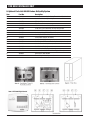
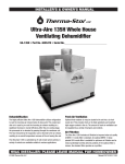
1
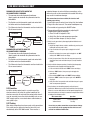
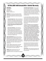
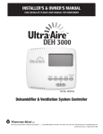
INSTALLER’S & OWNER’S MANUAL
HVAC INSTALLER: PLEASE LEAVE MANUAL FOR HOMEOWNER
P/N 4025700 • Serial No.___________________________
The Ultra-Aire 90H dehumidifier performs multiple functions in
a compact enclosure; high-capacity dehumidification, fresh air
ventilation, and particulate filtration.
Fresh Air Ventilation (optional)
Dehumidification
Air Filtration
The highly efficient UA-90H dehumidifier utilizes refrigeration to
cool the incoming air stream below its dew point. This cooled
and drier air is used to pre-cool the incoming air stream resulting
in increased overall efficiency. After the pre-cooling stage the
processed air is reheated by passing through the condenser coil.
The heat removed by the evaporator coil is returned to the air
stream, resulting in an overall temperature increase from the
incoming air.
Fresh air may be ducted to the unit and regulated by a variety of
controls in order to provide desired ventilation rates.
The UA-90H includes particulate filtration to improve the indoor
air quality of your living/working space. MERV-11 media filter is
standard.
P.O. Box 8680 Madison, WI 53708 • TOLL-FREE 1-800-533-7533 • www.thermastor.com • [email protected]
© 2007 Therma-Stor LLC • Manual P/N TS-325, 8/07
For small usage:
TABLE OF CONTENTS
Introduction ..............................................................................1
4.9A Setting the Time .....................................................9
Features & Benefits ..................................................................1
4.9B Ventilation Schedule ...............................................9
Safety Precautions . ..................................................................3
4.9C Automatic or Manual Mode ....................................9
1. Intended Application .............................................................4
5. DEH 3000 Digital Control ....................................................10
2. Registrations ........................................................................4
5.1.Specifications...............................................................10
3. Specifications .......................................................................4
5.2.Installation...................................................................10
4 . Installation . .........................................................................4
5.2A Install Instructions.................................................10
4.1 Installation Checklist .....................................................4
5.2B Wiring...................................................................10
4.1A Power Accessibility . ...............................................4
5.2C Auxillary Relay Operation.......................................11
4.1B Space ....................................................................4
5.2D Dehumidifier Lockout............................................11
4.1C Low Voltage Wiring . ...............................................4
5.2E Location................................................................12
4.1D Back-Draft Damper ................................................4
5.2F Testing...................................................................12
4.1E Support Structure and Suspension .........................4
5.3. Operation.....................................................................13
4.2 Electrical Requirements . ...............................................4
5.3A Display..................................................................13
4.3 Condensate Removal . ...................................................5
5.3B Setting..................................................................13
4.3A Lifting Condensate .................................................5
5.3C On/Off Setting......................................................13
4.3B Condensate Pump Kit .............................................5
5.3D Setting Clock Time...............................................13
4.4 Ducting ........................................................................5
5.3E Setting Relative Humidity Setpoint........................13
4.4A Fresh Air/Supply Air ................................................5
5.3F Fan Setting & Operation........................................14
4.4B Ducting for Fresh Air - Option .................................6
5.3G Damper Operation and Setting (Ventilation)..........14
4.4C Installation in a Basement or Crawlspace ...............6
5.3H Intermittent/Programmed Ventilation....................15
4.4D Installation in an Attic .............................................7
5.3 I Temperature Cutout Programming........................16
4.4E Installation in a Structure with
5.3J Default Settings....................................................17
No Forced Air HVAC System.............................................7
6. Control Package Diagram Sheet..........................................14
4.4F Ducting for High Efficiency Filtration........................7
7. Maintenance . .....................................................................18
4.5 Compressor Release and Noise Abatement.....................7
7.1 Standard Air Filter . ......................................................18
4.6 Controls . .......................................................................7
7.2 High Efficiency Air Filter ...............................................18
4.6A Humidity/Fan Control Panel
7.3 Optional Fresh Air Intake . ............................................18
WITHOUT Fresh Air Ventilation or Damper .......................8
8. Wiring Diagrams................................................................. 19
4.6B Humidity/Fan Control Panel WITH
9. Optional Parts List ..............................................................20
Fresh Air Ventilation and WITHOUT Damper ....................8
10. Service Parts List . ............................................................21
4.6C Humidity/Fan Control Panel WITH
11. Service .............................................................................22
Fresh Air Ventilation AND Damper ...................................8
11.1 Technical Description ................................................22
4.6D Ventilation Timer and Humidity Control
11.2 Troubleshooting .........................................................22
WITH Fresh Air AND Motorized Damper ..........................8
11.3 Refrigerant Charging .................................................23
4.6E DEH 2000 Digital Controller WITH
11.4 Compressor/Capacitor Replacement . ........................23
Fresh Air AND Damper ....................................................8
11.5 Electric Ventilation Damper . ......................................23
4.6F DEH 2000 Digital Controller
11.6 Condensate Pump Kit .......................................... 23-29
WITHOUT Fresh Air .........................................................8
Warranty ................................................................................30
4.7 Humidity Control Adjustment .........................................8
4.8 Fan/Filter Switch ...........................................................8
4.9 Ventilation Timer . ..........................................................9
2
Ultra-Aire 90H Installer’s & Owner’s Manual
SAFETY PRECAUTIONS
Read the installation, operation and maintenance instructions
carefully before installing and operating this device. Proper
adherence to these instructions is essential to obtain maximum
benefit from your Ultra-Aire 90H indoor air quality system.
READ AND SAVE THESE INSTRUCTIONS
• The device is designed to be installed INDOORS IN A SPACE THAT
IS PROTECTED FROM RAIN AND FLOODING.
• Install the unit with space to access the front panel for
maintenance and service. DO NOT INSTALL UNIT WITH THE FRONT
PANEL INACCESSIBLE.
• Avoid directing the discharge air at people, or over the water in
pool areas.
• If used near a pool or spa; be certain there is NO chance the unit
could fall into the water, splashed and that it is plugged into a GFCI
GROUND FAULT CIRCUIT INTERRUPT OUTLET.
• DO NOT use the device as a bench or table.
• DO NOT place the device directly on structural members.
• A drain pan MUST be placed under the unit if installed above a
living area or above an area where water leakage could cause
damage.
3
Ultra-Aire 90H Installer’s & Owner’s Manual
FOR HVAC INSTALLER ONLY
1. Intended Application for Ultra-Aire 90H
n4
.1C Low Voltage Wiring
Unit location should be in an area where field wiring the remote
controls (low voltage) to the unit will be possible.
For the ideal installation, draw air from the central part of the home
and return it to isolated areas of the home like the bedrooms, den,
utility room, or family room. The ductwork of the existing heating
system can be used to supply air to the home.
n4
.1D Back-Draft Damper
It is recommended that a back draft damper be used in the
discharge duct of the UA-90H, especially when connecting to the
supply ducting system. The backdraft damper prevents supply air
from counter flowing through the UA-90H when it is not operating.
The unit location should be chosen to allow installation of this
accessory if requested by the end user.
2. Registrations
The UA-90H conforms to UL STD 474 and CSA Standard C22.2
No.92.
3. Specifications
Model: Ultra-Aire 90H
Electrical: 110-120 VAC, 6.3 Amps, 60 Hz, grounded
Capacity: 90 pints/day @ 80°F, 60% RH
Operating Temp.: 56°F min., 100°F max.
Air Flow: 200 CFM without external ducting
Refrigerant Charge: 1 lb., 12 oz. R22
Duct Connections: Round 10" inlet, 10" outlet,
6" ventilation inlet Filter Size: Pleated cloth: 14" X 14" X 1"
Unit Size (w/o duct collars): 341/2"L x 153/4"W x 207/8"H Unit
Weight: 92 lbs Shipping Weight: 99 lbs
n4
.1E Support Structure and Suspension
Place the UA-90H on supports to raise the base of the unit. Do not
place the UA-90H directly on structural building members without
vibration absorbers or unwanted noise may result.
The UA-90H may be suspended with steel hanger straps (plumbers
tape) or a suitable alternative from structural members, as long
as the suspending assembly supports the UA-90H’s base in its
entirety. Do not hang the UA-90H from the cabinet. Remember to
place a drain pan under the unit if it is suspended above a finished
area or above an area where water leakage could cause damage.
4. Installation
4.1 Installation Checklist
4.2 Electrical Requirements
IMPORTANT
WARNING
Prior to installation of the UA-90H, the following checklist should
be reviewed. The UA-90H can be installed in a variety of locations
to meet the owner’s needs, and integrate with existing forced
air systems or existing ductwork if desired. The location choice
is contingent on a variety of requirements not limited to: ease
of service, controls access, drainage, filtration, power, fresh-air
ventilation, water damage prevention, and current regulatory codes
(ASHRAE, fire, etc). Please address all of these issues before you
select the device’s location.
WARNING: DO NOT ALLOW THE YELLOW LEAD FROM
THE ULTRA-AIRE TO CONTACT THE RED LEAD FROM THE
ULTRA-AIRE OR DAMAGE TO THE TRANSFORMER WILL
RESULT.
The UA-90H plugs into a common grounded 115VAC outlet. The
device draws 6.3 Amps under normal operating conditions. If used
in an area which may become wet, a ground fault interrupter (GFI)
protected circuit is recommended. Please, consult local electrical
codes for any further information.
n4
.1A Power Accessibility
Unit should be located in an area where the cord’s length (10’)
should easily reach a 115 VAC electrical outlet with a minimum of
a 15 A circuit capacity.
Therma-Stor LLC offers a family of control devices for use with the
UA-90H. The controls are to be located remotely from the unit and
located in the space to be conditioned. The controls are low voltage
(24 volt) and should be connected to the UA-90H with low voltage
wire (thermostat or other appropriate).
n4
.1B Space
Location should have enough clearance to handle the unit’s overall
dimensions as well as the necessary return/supply ductwork to the
unit.
4
Ultra-Aire 90H Installer’s & Owner’s Manual
FOR HVAC INSTALLER ONLY
remote location when the water level in the pump’s reservoir rises
to close the float switch. The pump also contains a safety float
switch. The white leads from this switch extend from beneath the
pump cover. This switch should be installed in series with the field
wire that connects the blue (#5) lead from the UA-90H to the the
control panel. If the pump fails, this switch opens the compressor
control circuit and stops water production before the reservoir
overflows. The UA-90H will continue to ventilate or circulate air as
normal, but will not dehumidify until this switch closes.
IMPORTANT
Do not install the control panel where it may not accurately
sense the relative humidity such as near HVAC supply
registers, near exterior doors, on an outside wall, near a
window, or near a water source.
The installer must supply the wiring between the UA-90H and the
control panel. Be sure to safely route the control wiring to prevent
damage during installation.
4.4 Ducting
IMPORTANT
CAUTION
Attention: For ventilation only! Remove label and 6’’ round
insulation from the duct prior to installing ducting for outside
ventilation. For all other applications leave in place.
Do not cross wires when connecting the UA-90H and the remote
control panel or damage to the transformer may result. The remote
controls of the UA-90H are powered by a low voltage circuit
(24VAC) and must NEVER contact or be connected to a high voltage
circuit.
For the ideal installation, draw air from the central part of the home
and return it to the isolated areas of the home like the bedrooms,
den, utility room, or family room. The ductwork of the existing
heating system can be used to supply air to the home. If the
existing supply goes to isolated areas of the home, discharge the
supply of the UA-90H into the supply of the existing heating system.
Installation of a separate supply duct to the UA-90H from a central
area is recommended.
The control wires leaving the UA-90H and the remote control
panels are numbered and color-coded to prevent confusion. Some
of the control wires leaving the UA-90H may not be used with
certain control panels and should be left unconnected with wire
nuts taped onto the stripped ends for safety. Be sure to consult the
electrical schematic in this manual or inside the access panel of
the UA-90H before making control connections.
4.4A Fresh Air/Supply Air
4.3 Condensate (Water) Removal
IMPORTANT
IMPORTANT
DO NOT draw air directly from the kitchen, laundry, or isolated
basement.
A trap in the drain line is preferred, but not required for the unit to
drain properly. Local codes may require a trap. Use care to keep the
pipe assembly as flat to the floor as possible. Kinks and/or humps
will prevent proper drainage. The UA-90H generates condensate.
Install a 3/4" male nominal pipe thread adapter to the drain pan.
It is necessary to assemble your own drain pipe assembly utilizing
3/4" PVC pipe to get the condensate to a floor or other drain. Pipe is
commonly available in 10’ lengths from building supply, plumbing
or hardware stores. Grade of pitch should be 1" per 10'.
You may draw air from a basement that is open to the home. All
flexible ducting connected to the UA-90H should be UL listed.
A short piece of flexible ducting on all UA-90H duct connections
is recommended to reduce noise and vibration transmitted to
rigid ductwork in the structure. Ducting the UA-90H as mentioned
requires consideration of the following points:
Duct Sizing: For total duct lengths up to 25’, use a minimum 10"
diameter round or equivalent rectangular. For longer lengths, use a
minimum 12" diameter or equivalent. Grills or diffusers on the duct
ends must not excessively restrict airflow.
4.3A Lifting Condensate
An optional condensate pump kit may be installed if a lift is
required to dispose of the condensate. The condensate pump can
be ordered direct from the factory. See the optional parts list in
Section 8 for information on the kit.
4.3B Condensate Pump Kit
An optional condensate pump kit is available from the factory for
use with the UA-90H. Condensate is automatically pumped to a
5
Ultra-Aire 90H Installer’s & Owner’s Manual
FOR HVAC INSTALLER ONLY
Isolated Areas: Effective dehumidification may require that ducting
be branched to isolated, stagnant air flow areas. Use 8" or larger
diameter branch ducting to each of two or three areas, use 6" or
larger to each of four or more areas. Provisions must be made to
provide airflow from supply locations to central return location.
Proper air distribution is important to ensure even humidity control
and heat distribution throughout the structure. See Figure 1.
In cold climates or areas where the outdoor dew point is low at
times, ventilation can be used to dehumidify the structure, making
the UA-90H capable of year-round drying. This is accomplished
by bringing the dry, low dew point air into the structure during
these times. This approach is often more economical than running
the dehumidifier to remove excess moisture from the structure.
In cold climates, it is critical to adequately ventilate to reduce the
inside moisture content to avoid moisture accumulating in the wall
cavities. For example; in a house that experiences condensation on
the interior surface of the windows during the winter, increasing the
amount of ventilation will often cure the problem.
An insulated 6" diameter duct is generally sufficient to provide up
to 75 CFM of outside air. Large quantities of outside air will impact
UA-90H performance positively or negatively, depending upon the
inside and outside air conditions.
Connecting to existing HVAC systems: An optional 10" check
backdraft damper is available from the factory to prevent reverse
air flow through the UA-90H. If the UA-90H is ducted to the supply
of an air handler, the check damper should be placed in the UA90H supply duct. Ventilation operation is controlled by the remote
controls offered with the UA-90H. These controls determine the
time/frequency that the unit introduces outside air. The amount of
outside air can be restricted by the blade damper in the 6" collar.
Some control options require a 6" motorized damper be installed in
the 6" fresh air duct.
The outside air duct should be connected to the 6" round collar on
the front of the unit. The amount of outside air can be restricted
by the blade damper in the 6" collar. These controls determine
the time/frequency that the unit introduces outside air. The
amount/frequency of ventilation should be based on the size and
occupancy of the residence. If you are unsure of your ventilation air
requirements or have need for higher air flows, consult the factory
by calling 1-800-533-7533 for assistance.
4.4C Installation in a Basement or Crawlspace with an
Existing Forced Air HVAC System.
IMPORTANT
Contact the factory when connecting to a static pressure of
greater than or equal to +.5" WG.
4.4B Ducting for Fresh Air — Option
Fresh air may be brought into the structure by connecting an
insulated duct from outside the structure to the 6" inlet of the UA90H. Advantages of this form of ventilation include:
1. Outside air is filtered before entering the building.
2. Outside air will be dehumidified before entering if the UA-90H
is running in dehumidification mode.
3. Drawing air from outside and blowing inside aids in slightly
pressurizing the structure. This helps prevent dirty and humid
air from entering elsewhere. It also reduces the potential for
carcinogenic radon gas to enter and provides a small amount
of make-up air for open combustion and exhaust devices like
the clothes drier, fireplace, and water heater.
4. Exhaust fans are recommended in the bath rooms and
kitchen.
Basement Installation: Install a separate 10" return for the UA90H in a central area of the structure. Optional: Duct the supply
of the Ultra-Aire to a 10" x 10" x 10" tee/damper, adjusted to
20% open to the basement. Duct the other side of the tee to the
air supply of the existing HVAC system with a backdraft damper.
Connect a duct from outside to the 6" collar of the Ultra-Aire if you
wish to provide ventilation air. See Figure 2.
6
Ultra-Aire 90H Installer’s & Owner’s Manual
FOR HVAC INSTALLER ONLY
4.4E Installation in a Structure with No Existing Forced
Air HVAC System
Crawlspace Installation: Install a separate return for the UA-90H
in a central area of the structure. Optional: Duct the supply of the
UA-90H to a 10" x 10" x 10" tee/damper that is 20% open to
the crawlspace if desired. Duct the other side of the tee to the
air supply of the existing HVAC system with a backdraft damper.
Connect an insulated duct from outside to the 6" collar of the UA90H if you wish to provide optional ventilation air.
When installing the UA-90H in a structure that does not have a
forced air HVAC system, a single return for the UA-90H should
be installed in central open area of the structure. DO NOT locate
the return in a bathroom or a kitchen. The supplies of the UA90H should be located in the remote areas of the structure (such
as bedrooms, den, etc.). By ducting this way, the air inside the
structure will circulate through the UA-90H to be filtered and
dehumidified. 6" diameter duct is recommended for branches to
the bedrooms, 8" diameter duct is recommended for branches
to larger areas. Connect an insulated duct from outside to the 6"
collar of the UA-90H if you wish to provide ventilation. See Figure 4.
Instead of installing a separate return to the UA-90H, and if the
existing system has multiple returns, it is possible to select one to
disconnect from the existing forced air system and use it for the
dedicated Ultra-Aire return. Always select a return from a central
location in the structure in an area that is always open to the rest
of the structure. Do not use a return from a room that may have
its door closed much of the time or, alternatively, install a separate
return from the open part of the house.
4.4D Installation in an Attic with an Existing Forced Air
HVAC System
IMPORTANT
ALWAYS install a catch pan with a drain or float interrupt for
condensate under the UA-90H in an attic or condensate may
damage the living space below.
4.4F Ducting for High Efficiency Filtration
The interrupt switch should be installed in series with the field wire
that connects the blue (#5) lead from the UA-90H to the blue (#5)
lead on the control panel. If overflow occurs, this switch opens
the compressor control circuit and stops water production before
the catch pan overflows. The UA-90H will continue to ventilate or
circulate air as normal, but will not dehumidify until this switch
closes.
The standard filter included with the UA-90H is a very effective
MERV 11 media filter. Additional filtering options, including charcoal
filtration and 95% efficient filtration, are available with an optional
external filter housing that may be installed with the UA-90H. The
filter box is ducted to the intake of the UA-90H, and the intake
ducting is then connected to the intake side of the filter box. See
the optional accessories list or call the factory for details.
The preferred method of installation is to create a separate return
for the UA-90H in a central area of the structure. Duct the supply of
the UA-90H to the air supply of the existing HVAC system. Connect
an insulated duct from outside to the 6" collar of the UA-90H if you
wish to provide fresh make-up air. Adjust a damper in the duct to
provide the desired.
4.5 Noise Abatement
A length of 10 feet or more of acoustical flex ducting on the outlet
of the UA-90H will reduce air noise from the fan. A length of flexible
ducting on all UA-90H duct connections is recommended to reduce
noise transmitted to rigid ductwork in the structure.
4.6 Controls
All control panels should be mounted in a central area of the
structure where it can accurately sense the humidity of the air in
the living space and be accessed. All controls require field wiring
from the unit location to the panel mount location.
Figure 1:
Humidity/Fan Control Panel
Part No. 4024155
7
Figure 2: Ventilation Timer
and Humidity Control Panel
Part No. 4024125
Ultra-Aire 90H Installer’s & Owner’s Manual
FOR HVAC INSTALLER AND HOMEOWNER
To determine how each control operates the UA-90H, it must
first be determined which control is being used and whether
or not the 90H is ducted for fresh air ventilation. Refer to
appropriate section.
When the fan/filter switch is in the “ON” position, the motorized
damper will open and the fan will run, introducing outside air. The
unit may or may not be dehumidifying in the ventilation mode,
depending on the humidity control setting. See Section 4.7 for
humidity control operation.
Humidity/Fan Control Panel (P/N 4024155) (Figure 1, p.7)
4.6A Humidity/Fan Control Panel WITHOUT Fresh Air
Ventilation or Damper
4.6B Humidity/Fan Control Panel WITH Fresh Air
Ventilation and WITHOUT Damper
4.6C Humidity/Fan Control Panel WITH Fresh Air
Ventilation AND Damper
4.6D Ventilation Timer and Humidity Control WITH
Fresh Air AND Motorized Damper
Refer to sections 4.7 through 4.9C.
4.6E DEH 2000 Digital Control WITH Fresh Air AND
Damper
Refer to Section 5.
Ventilation Timer/Humidity Control Panel (P/N 4024125)
(Figure 2, p.7)
4.6D Ventilation Timer and Humidity Control WITH Fresh Air
AND Motorized Damper
4.6F DEH 2000 Digital Control WITHOUT Fresh Air
Refer to Section 5.
4.7 Humidity Control Adjustment
DEH 2000 Digital Control (P/N 4024539) (Figure 1, p.10)
4.6E Digital Controller WITH Fresh Air AND Damper
4.6F Digital Controller WITHOUT Fresh Air
Set the humidity control to the desired
humidity level for the home. Turning the knob
clockwise results in a drier setting. See the
back of the control panel cover for set points.
The dehumidifier will run continuously until
the relative humidity (RH) is reduced to the
Figure 3
humidity control dial setting. Setting the
Humidity Control
humidity control to lower RH levels will NOT
Adjustment Knob
increase the dehumidification rate; the unit will
simply run longer to reduce the RH to the setting. The UA-90H unit
(and refrigerant-based dehumidifiers in general) will reduce a warm
space’s RH to a lower level than that of a cool space. Therefore
there is no benefit to set the humidity control to excessively
low levels in cool rooms; doing so will result in long periods of
ineffective dehumidifier run time. Settings below 45% are not
recommended.
4.6A Humidity/Fan Control Panel WITHOUT Fresh Air
Ventilation or Damper
The humidity/fan control panel automatically controls the humidity
of the living space. The humidity/fan control panel contains an
adjustable humidity control and a fan switch. The panel has a
cover that must remain open to the air within the living space for
accurate humidity sensing. When the fan switch is in the “ON”
position, air will be continually filtered and circulated throughout
the home. For humidity control operation refer to section 4.7.
4.6B Humidity/Fan Control Panel WITH Fresh Air
Ventilation and WITHOUT Damper
The humidity/fan control panel automatically controls the humidity
of the living space. The humidity/fan control panel contains an
adjustable humidity control and a fan switch. The panel has a
cover that must remain open to the air within the living space for
accurate humidity sensing. Outside air is continually introduced
whenever fan is “ON.” Manual operation of fan filter switch controls
outside air ventilation. Since the fan operates whenever the UA-90H
is dehumidifying outside air will also be introduced. For humidity
control operation refer to section 4.7.
4.8 Fan/Filter Switch
Turning ON the fan/filter switch will cause the
UA-90H fan to run continuously, whether the
UA-90H is dehumidifying or not. This function
is desirable if the unit is used for air circulation
and filtration to achieve maximum indoor air
quality. When the switch is ON; air will be
Figure 4
constantly filtered through the UA-90H and
Fan/Filter Switch
circulated throughout the house. When the
switch is OFF the fan will operate only when the humidity control
calls for dehumidification or when the ventilation timer calls for
ventilation.
4.6C Humidity/Fan Control Panel WITH Fresh Air
Ventilation AND Damper
In this configuration, a motorized damper has been installed
in the fresh air duct. When the fan/filter switch is in the “OFF”
position, the damper is closed. The UA-90H will then circulate and
dehumidify air to provide humidity control.
8
Ultra-Aire 90H Installer’s & Owner’s Manual
FOR HVAC INSTALLER AND HOMEOWNER
4.9 Ventilation Timer
4.9B Ventilation Schedule
The ventilation timer controls the fan and the motorized fresh
air damper. When the ventilation timer is activated, the UA-90H
will circulate the indoor air, and bring in fresh air from outside.
The ventilation timer should be set for the required ventilation
of the residence. The home should be ventilated with fresh air
as suggested by applicable codes and standards or as required
by the homeowner. The ventilation timer is an electronic timer
that displays the current time. This timer has battery backup,
so it will not require resetting after a power outage. Following
a prolonged power outage the display of the timer will flash on
and off indicating a power outage has occurred. The one-minute
time increments of the ventilation timer allow you to program the
ventilation of your home to fit your schedule.
Slide the switch in the upper right hand corner to the program
symbol P. “ON” will appear to the right of the time and the number
“1” will appear in the lower right hand corner of the display. The
“1” and “ON” signify the turn on time for the first program. Press
the 1-7, h and m button to choose the days of the week for this
program. You can choose Mon.-Sun., Mon.-Fri., Sat.-Sun., or any
single day of the week. The days chosen are shown along the top
of the display on the ventilation timer. Next press the h button to
set the hour for the start of the ventilation period. Remember this
timer operates on a 24-hour clock (military time). Then press the m
button to set the minutes past the hour to start the ventilation.
Humidity/Fan Control Panel
Part No. 4024155
Now, with the ventilation start time set; press the I/O button. The
word “OFF” should appear to the right of the time and the number
“1” should remain in the lower right hand corner of the display. The
“1” and “OFF” signify the turn off time for the first program. Set
the turn off time using the 1-7, h and m buttons in the same way
as described above and continue on to the second through sixth
programs. When setting the ventilation programs, you can return
to the current time display by sliding the switch in the upper right
corner of the timer to RUN. The slide switch must be set to RUN for
the timer to operate its scheduled programs.
Ventilation Timer & Humidity
Control Panel
Part No. 4024125
4.9C Automatic or Manual Mode
The ventilation timer allows six programs with each program
having one “ON” and one “OFF” event. A program allows the
user to turn the ventilation on at a certain day and time, then it
allows them to turn the ventilation off at a certain day and time.
Each of these programs can be repeated daily or weekly or
during a specified block of days. All six of the programs operate
independently of each other. If the timer fails to operate or operates
erratically, check that the control panel receives 24Vac from the
UA-90H. If 24Vac is present at the control panel, reset the timer by
pressing the reset button at the bottom center of the timer face.
The reset button is the small recessed button with an R beneath
it located below the 1-7 and h buttons. Depress the reset button
until the display clears. Release the reset button. The display will
reappear as 00:00. Resetting the timer will clear the time and all
program settings. After resetting the timer follow the instructions
below to set the correct time and ventilation programs.
The slide switch in the upper left of the timer is used to choose
between automatic and manual operation. When the slide switch
is set to AUTO mode, the UA-90H will ventilate when the scheduled
programs call for ventilation. When the slide switch is set to manual
(set to hand symbol on the right), the operation of the timer is
controlled by the I/O button only. Pressing the I/O button will switch
the ventilation timer between ON (detent) and OFF (detent). As you
press the I/O button, “ON” or “OFF” will be displayed to the right of
the time. The “ON” or “OFF” indicates if the ventilation timer is on
or off. The I/O button will manually override scheduled programs if
the timer is in AUTO mode.
4.9A Setting the Time
Set the correct time on the timer by sliding the switch in the upper
right hand corner of the timer to the clock symbol. and pressing the
1-7 (DAY), h (HOUR), and m (MINUTE) buttons. Remember this timer
operates on a 24-hour (military time) clock.
9
Ultra-Aire 90H Installer’s & Owner’s Manual
FOR HVAC INSTALLER ONLY
5. DEH 3000 Digital Control
Installation Instructions
8. Test connections (see Section 2.6)
Control Part No. 4026570
5.1 Specifications
Part # (P/N)
Model:
Electrical:
Humidity Range:
Humidity Accuracy:
Output:
Relay Capacity
Temp Range/Accuracy
Size
4026570
DEH 3000 Digital Control
24 VAC
10 – 95% RH
+/- 5%
3 Amps 24 VAC
5 Amps
2%
4.95" wide x 4.19" high
5.2B Wiring
FOR HVAC INSTALLER ONLY:
WARNING: DO NOT ALLOW THE YELLOW LEAD
FROM THE ULTRA-AIRE TO CONTACT THE RED OR WHITE LEADS
FROM THE ULTRA-AIRE OR DAMAGE TO THE TRANSFORMER
WILL RESULT
5.2 Installation
This control panel must be installed in the conditioned space
and in accordance with all applicable codes and standards.
Follow the instructions below when installing and setting this
control.
WARNING: UNPLUG ULTRA-AIRE BASE UNIT
BEFORE WIRING CONTROL.
The installer must supply the wiring between the Ultra-Aire
and the control panel. Be sure to safely route the control wires
to prevent damage during installation. Be careful not to cross
the wires when connecting the Ultra-Aire and the remote
control panel or damage to the transformer may result.
5.2A Install Instructions
1.Separate the front panel from the back panel by
depressing the middle sections of the top and bottom of
the front panel.
2.Line the back panel up against the wall or flat surface
onto which it is to be mounted and drill in the appropriate
mounting holes.
3.Insert the screws and tighten down so they extend
approximately 1/8” from the back plate.
4. Align the back panel so that the control is level.
5. Tighten the screws to lock into position.
6.Make the electrical connections to the terminals on the
back panel as shown in the wiring diagram.
7.Reassemble the front to the back panel. Connect at the top
first, then at the bottom.
The remote control of the Ultra-Aire is powered by a low
voltage circuit (24 VAC) and must NEVER contact or be
connected to a high voltage circuit. Some of the control wires
leaving the Ultra-Aire may not be used with certain control
panels and should be left safely disconnected with wire nuts
taped onto the stripped ends. Be sure to consult the electrical
schematic in this manual or on the front panel of the UltraAire before making the control connections.
10
Ultra-Aire 90H Installer’s & Owner’s Manual
FOR HVAC INSTALLER ONLY
Green
Yel
low
Red
COM/NO
COM/NC
ON
CLOSED
OPEN
OFF
OPEN
CLOSED
Common uses (assuming standard thermostat wiring color
schemes as noted):
24 VAC
DAMPER
optional
Blue
UA Base Unit
White
Dehumidification
Operation
Disengage A/C during dehumidification
Redirect the yellow thermostat wire to the NC
terminal. Wire the yellow wire from the A/C to the
COM (B) terminal.
DEH 3000 Wiring Diagram
Engage A/C during dehumidification
Connect a wire from the “R” terminal on the the
thermostat to the “com” terminal on the DEH 3000.
Connect a wire from the “NO” terminal on the DEH
3000 to the “Y1” terminal on the thermostat.
DMP COMP FAN
WARNING: TO AVOID TRANSFORMER DAMAGE
ONLY CONNECT WHITE WIRE TO CONTROL IF DAMPER IS USED.
5.2D Dehumidifier lockout/activation AC sensor
The white wire controls the optional motorized damper
that can be installed into a fresh air duct. This provides
the ability to control when fresh air is introduced into the
building by using the ventilation timer function labeled
“DMP” on the control (See Section 3.7). If the motorized
damper is not used, DO NOT CONNECT THE WHITE WIRE
TO THE CONTROL OR DAMAGE TO THE TRANSFORMER
MAY RESULT. Simply leave the (DMP) terminal unused if
the damper is not used, and cap off the white lead fro mthe
Ultra-Aire base unit.
The control has the ability to activate the dehumidifier or
deactivate the dehumidifier when the air conditioner is
running.
5.2C Auxiliary relay operation
At times it may be desirable to coordinate fan operation
of the central heating/cooling system with dehumidifier
operation. The DEH 3000 features a relay that provides
this ability. The relay terminals labeled NC, COM and
NO operate according to the following chart:
Standard wire colors for thermostats are as follows:
11
Description
Color
Terminal code
24VAC Return
Red
R
Call for Heat
White
W or W1
Force Fan On
Green
G
Compressor
Call for Cooling
Yellow
Y or Y1
Ultra-Aire 90H Installer’s & Owner’s Manual
FOR HVAC INSTALLER ONLY
DEHUMIDIFIER DEACTIVATES WHEN THE
AIR-CONDITIONER IS RUNNING
•The common wire on the thermostat transformer
(black) needs to be wired with the yellow wire from the
dehumidifier.
motorized damper in series with these connections, or the
white wire must not be connected to the control. Mis-wiring
may result in transformer damage.
•The Red wire on the thermostat needs to be wired with
the Yellow wire from the dehumidifier.
1. Install front cover of control; insert at top first, then bottom.
After connections have been verified, this short test will
confirm proper wiring.
2. Plug in Ultra-Aire base unit. The control should power up.
•The Yellow wire from the thermostat must be wired to the
AC off sensor terminal.
3. Turn control on by pressing the ON/OFF button.
4. Engage dehumidification operation by adjusting RH
setpoint below ambient conditions.
a. Press RH until RH setpoint is 20%.
b. Verify Ultra-Aire fan and compressor operation.
c. Verify ventilation damper (if used) is closed.
DEHUMIDIFIER
BLACK
YELLOW
RED
YELLOW
5. Verify fan only operation by disengaging dehumidification and
operating fan:
a. Adjust RH setpoint above ambient conditions by pressing and
holding RH until set point is 80%.
b. Press fan button, then press again to toggle fan to “ON”
setting.
c. Release fan button, then press again to toggle fan to “on”
setting until “fan” flashes on display.
d. Verify fan operation of Ultra-Aire. No compressor operation
should be noted, and ventilation damper (if used) should be
closed.
AIR CONDITIONER
TRANSFORMER
THERMOSTAT
DEHUMIDIFIER
ACTIVATES WHEN THE
DEHUMIDIFIER
AIR-CONDITIONER IS RUNNING
YELLOW
•
The common wire on the thermostat transformer BLACK
RED
(black)
needs to be wired with the yellow wire from the
DEHUMIDIFIER
dehumidifier. YELLOW THERMOSTAT
AIR CONDITIONER
BLACK
TRANSFORMER
YELLOW
•The Red wire on the thermostat needs
RED to be wired with
the Yellow wire from the dehumidifier.
YELLOW
AIR CONDITIONER
THERMOSTAT
6. Verify ventilation damper operation (if installed) by disengaging
from operation and engaging ventilating operation.
a. Press and hold fan button until “fan” flashes on display.
b. Release “fan” button, then press again to toggle fan
operation off.
c. Press and hold “vent” button until “vent” flashes on display.
d. Release “vent” button, then press again until “open” is
displayed.
e. Verify Ultra-Aire fan operation and ventilation damper is open,
with no compressor operation.
•The Yellow wire from the thermostat mustTRANSFORMER
be wired to the
AC on sensor terminal.
DEHUMIDIFIER
BLACK
YELLOW
RED
YELLOW
THERMOSTAT
AIR CONDITIONER
TRANSFORMER
7. If any functions are not working properly, verify wiring and
connections. Meters may be used across terminals to verify voltage.
If there is a concern about the base unit not operating properly, the
leads exiting the base unit may be connected and operation verified
according to the following matrix:
5.2E Location
Install the remote control panel in a central area of the
structure where it will sense the relative humidity of the
structure accurately. Do not install the control panel where it
may not accurately sense the relative humidity such as near
HVAC supply registers, near exterior doors and windows, or
near a pool or spa.
5.2F Testing
After wiring connections have been made, verify connections.
First, make sure the white wire from the base unit is not
wired directly to the DEH 3000 control. There must be a
Wire connections
Yellow & Blue
Yellow & Green
Operation
Fan & Compressor
Fan Only
Do not test any other connections or transformer damage
may result. Refer to the appropriate Ultra-Aire base unit
manual for additional information.
12
Ultra-Aire 90H Installer’s & Owner’s Manual
FOR HVAC INSTALLER AND HOMEOWNER
8. Verify additional optional control operations such as fan interlock
or lockout.
9. Proceed to operation/setting section.
FOR INSTALLER & HOMEOWNER:
5.3 Operation
5.3A Display
•When there is power to the control, the control display will
show the time, day, humidity, and temperature.
•When the control is turned on, the setpoint, fan status,
auto/hold mode, and fresh air vent status is displayed.
• When a key is pressed the display will light.
•The “Time” and “Day” is displayed at the top of
the screen.
• RH and Temperature are displayed in real time.
•An “O” before the set point, vent, or fan indicates the unit
is operating the device.
•A flashing “O” before the set point, vent, or fan indicates
the unit is in a delay prior to operating the device.
5.3D Setting Clock Time
1.Press and hold the “CLOCK” button. The hour display
will flash. Release the button.
2. Use the “UP/DOWN RH” buttons to change the value.
3.Press the “CLOCK” button again and the minute display
will flash. Use the RH buttons to change the value.
4.Press the “CLOCK” button again and the “AM/PM” display
will flash. Use the RH buttons to toggle the value.
5.Press the “CLOCK” button again and the day display will
flash. Use the “RH” buttons to change the value.
Note: Delay is an intentional factory installed time delay
cycle that is meant to prevent short cycles, extending the
life of the Ultra-Aire. If a delay is encountered, WAIT 10
MINUTES BEFORE EXPECTING NORMAL OPERATION.
5.3B Setting
During the set-up process, if you make a mistake, simply
continue. You can always go back to adjust the settings. If
you leave the control alone and don’t touch any buttons for
10 seconds, the control will remember any changes made
and return to “home.”
If the “CLOCK” button is pressed again or no button is
pressed for 5 seconds, the display will automatically return to
“home.”
5.3C On/Off Setting
5.3E Setting Relative Humidity Setpoint
Press the “ON/OFF” button to turn the system on or off.
When the system is on, the setpoint, fan status, auto/hold
mode, and fresh air vent status is displayed. In the off
mode, the control will show the time, day, humidity, and
temperature. When the unit is shipped, it is in manual mode.
The relative humidity setpoint (the average RH that is
maintained) operates the dehumidifier function of the UltraAire. It has no effect on any other function of the unit. The
control senses the ambient relative humidity of the space in
which it is located.
13
Ultra-Aire 90H Installer’s & Owner’s Manual
FOR HVAC INSTALLER ONLY AND HOMEOWNER
Operation
The initial dead band setting (the range that the dehumidifier
cycles on and off) is 3%. With a setpoint of 50%, the dumidifier
turns on when the reading reaches 53%. The dehumidifier
continues to remove water from the air until the reading is
47%. The dehumidifier remains off until the reading is 53%.
continuously are filtration and air recirculation.
“AUTO” – indicates the fan will run when the control calls for
dehumidification or ventilation. If the control has not called for
dehumidification for 3 hours, the control will automatically run
the fan for 10 minutes. The fan must run a specific amount of
time per day. This helps to keep the dehumidifier dry.
AMBIENT RH
After dehumidification cycle, fan automatically shuts off for 10
minutes.`
To set the operation:
1.Press and hold the “FAN” button. The current fan setting
will begin to flash. Release the button.
2.Press the “FAN” button to toggle between the “ON” and
“AUTO” modes.
CURRENT SETPOINT
If the setpoint is equal to or greater than the current ambient
condition, the space does not need to be dried so the
dehumidifier function will be off.
Example: Setpoint: 50% RH
Current condition: 45% RH = Dehumidifier off, the “O”
indicator will not be shown.
FAN MODE
(Auto or On)
If the setpoint is less than the ambient condition, the
dehumidifier will be on and the red “DEHU” indicator will be
lit. Since the space is more humid than the set point, the
controller operates the dehumidifier to dry the space.
An “O” indicator indicates the fan is operating. A flashing
“O” indicator indicates the fan is in a wait mode and will
operate shortly. No “O” indicates the fan is off.
Example: Setpoint: 50% RH
Current condition: 55% RH = Dehumidifier on, the “O”
indicator will be shown.
With the fan in the “auto” mode, the fan will operate only
when needed by other functions of the system. The fan
will remain off unless the system is dehumidifying and/or
ventilating. The fan always runs during dehumidification and
ventilation and the fan “O” icon will be lit. To completely turn
the system off, use the “ON/OFF” button as described earlier.
To adjust the ventilation mode see Section 3.7.
To set the relative humidity setpoint, press up or down “RH”
buttons to adjust the relative humidity setpoint as desired.
Therma-Stor recommends relative humidity levels not exceed
50% in the summer, and 25-35% in the winter if you live
in a cold climate. It is not recommended that the humidity
setpoint be set below 35%. In order to dry the home in the
winter in a cold climate, use the ventilation function of the
system rather than the dehumidifier function. Call the factory
or refer to the owner’s manual for more information.
5.3G Damper Operation and Setting (Ventilation)
Manual/Hold Mode
5.3F Fan Setting and Operation
Ultra-Aire units can be installed to incorporate optional ventilation.
The damper setting controls the ventilation function of the system.
It has no control over the dehumidification function, although
the ventilation function can and should be used to dry the space
depending on the climate and the outside air conditions. Refer to
the appropriate Ultra-Aire manual for more information.
“ON” – indicates the fan of the Ultra-Aire will run
continuously. This does not affect either the dehumidification
or ventilation functions of the system. In other words, the
system may or may not be ventilating or dehumidifying while
the fan is running. Common reasons for operating the fan
In order to provide ventilation, the damper must be open (“ON”)
and the fan must be running. The controller takes care of these
two functions automatically, so that whenever the damper is open
(“ON”), the fan is running.
Use the “FAN” button to adjust the fan operation. There are
2 choices for fan operation: “ON” or “AUTO.”
14
Ultra-Aire 90H Installer’s & Owner’s Manual
FOR HVAC INSTALLER ONLY AND HOMEOWNER
The ventilation indicator “O” will be displayed whenever the unit
is ventilating. The fan operation indicator “O” will also be lit.
There are two programs available for ventilation Monday
through Friday. There are also two programs for Saturday and
Sunday. No other choice of days is available.
There are three damper operation modes, “OPEN – hold,”
“CLOSED – hold” and “PROGRAM” (denoted by “ON TIME”
– “OFF TIME.” Refer to section 3.8). With the damper in the
“OPEN – hold” mode, the damper will be open and the fan of
the system will be operating in order to introduce fresh air into
the space. Use this mode for continuous fresh air ventilation. The
fan is always on when the damper is open. When in “CLOSED
– hold” mode, the damper will not open and the system will not
ventilate.
Each program has:
•A “START” time of day when the ventilation schedule
begins.
•An “OPEN FOR” duration for the amount of time the
damper stays open in 5 minute intervals, from 0 to 60.
•A “CLOSED FOR” duration which closes the vent for a
specified time in 5 minute intervals from 0 to 60.
Example:
1.Press “program enter” button. The following menu
appears:
When in the “program” mode, the control will operate the damper
and fan (ventilate) according to the programmed ventilation
schedule (See Section 3.8).
To set the damper operation:
1.Press the “VENT” button. The current setting will begin to
flash on the display. Release the button.
2.Press the “VENT” button again to toggle between “open,”
“closed” and “program.”
3.Leave the control alone for 10 seconds to select the indicated
damper mode and return to “home.”
2.Using the up/down RH buttons, select “program.” The
following menu appears:
5.3H Intermittent or Programmed Ventilation
You can select from:
“MON-FRI” or “SAT-SUN” for separate weekday/weekend
schedules or “MON-SUN” which gives you equal weekday/
weekend schedules.
This example shows the damper in “PROGRAM” mode
(denoted by the schedule 15 minutes on, 5 minutes off).
Menu when you select “MON-FRI” or “SAT-SUN”:
The status of the damper is show here.
is open, blank is closed.
The system will operate the ventilation function according to the
current ventilation program. The control needs to be programmed
to turn the ventilation function on and off at the desired intervals.
This is done by programming the ventilation timer.
1.Enter the starting time for weekdays using the up/down
RH keys to change the time.
15
Ultra-Aire 90H Installer’s & Owner’s Manual
FOR HVAC INSTALLER AND HOMEOWNER
2. Press the program enter key to toggle to the “open for”
setting. Using the up/down “RH” keys, change the
duration that the damper will ventilate fresh air.
feature will not need to be used. If temperature cutout is desired,
program the setpoint by pressing the “program enter”
button. Press RH until “temp cutout” is flashing. Use “RH”
up or “RH” down to adjust setpoints.
3. Press the program enter key to toggle to the “closed
for” setting. Using the up/down “RH” keys, change the
duration that the damper will remain closed between
ventilation.
5.3J Default Settings
Upon initial power-up or after prolonged power outages (more
than 30 minutes), the DEH 3000 is programmed with the
following defaults. A space is provided to make note of user
inputs.
For the example given, starting at 8:00AM in the morning,
the control will ventilate fresh air for 15 minutes then stop for
15 minutes. This schedule of 15 minutes open; 15 minutes
closed will continue until the start time of the night schedule.
Setting
Default
My Setting
Press “program enter” again to go to the “MON-FRI”
night schedule. Repeat the steps listed above for this and the
“SAT-SUN” day and night schedules.
RH setpoint
50%
__________
Ventilation Operation
Closed
__________
When you return to the main program menu, use the
up/down “RH” buttons to select “run program.”
Fan Setting
Auto
__________
Temp Cutout
80%
__________
If you have questions about the
DEH 3000, please call Therma-Stor LLC
at 1-800-533-7533 or email us at
[email protected]
Press “program enter” to run the program. The
display will appear as follows:
Vent schedule
on time/off time
Program
RUN mode
5.3I Temperature Cutout Programming
Ultra-Aire units produce heat when dehumidifying. Depending
on outside conditions, the ventilation function may introduce
warm air into the space. Occasionally, the operation of the
Ultra-Aire may produce enough heat to drive temperatures up.
The temperature cutout feature disables all Ultra-Aire operations
if temperatures reach cutout setpoint. In most installations this
16
Ultra-Aire 90H Installer’s & Owner’s Manual
ATTENTION INSTALLER
WIRE THE UNIT AND CONTROL PACKAGE AS SHOWN IN THE DIAGRAM BELOW
Humidity/Fan Control Panel
Humidity
Control
D.BLU-5
YEL-2
2 1
Blower
Switch
3
GRN-6
PNK
GRN-6
WHT-1
RED-3
YEL-2
D.BLU-5
Dehumidifier
Control Part No. 4024155
Ventilation Timer/
Humidity Control Panel
Do not connect these leads
directly together or damage
to the transformer will result.
Optional
Damper
Humidity
Control
D.BLU-5
YEL-2
3 2 1
PNK
REd-3
GRN-6
WHT-1
RED-3
YEL-2
D.BLU-5
5
Timer
3 2 1
VIO-4
ORG
GRN-6
L.BLU
GRY
Control Part No. 4024125
Dehumidifier
DEH 3000 Digital Control
Green
Red
Yel
low
24 VAC
optional
DAMPER
Blue
UA Base Unit
White
DMP COMP FAN
Control Part No. 4026570
WARNING: DO NOT allow the yellow lead from the unit to contact the red lead or the white lead from the
unit or damage to the transformers will result. Do not direct connect the white lead on the unit to the violet
lead on the ventilation control or damage to the transformer will result.
17
Ultra-Aire 90H Installer’s & Owner’s Manual
FOR HVAC INSTALLER AND HOMEOWNER
7. Maintenance
7.1 Standard Air Filter
The UA-90H is equipped with a MERV 11 media filter. This filter
should be checked every three months. Operating the unit with
a dirty filter will reduce dehumidifier capacity and efficiency and
may cause the compressor to cycle off and on unnecessarily on the
defrost control.
DO NOT operate the unit without the standard filter or with a
less effective filter than the standard filter. The heat exchange
coils inside the unit could become clogged and require
disassembly to clean. Filter non-compliance invalidates the
product warranty.
7.2 High Efficiency Air Filter
Most filters are labeled with a MERV rating number, which
measures a filter’s ability to trap particles ranging in size from 3.0
microns to 10.0 microns. Residential filters commonly have MERV
ratings of 1-12. The higher the MERV rating, the more efficient the
filter is, and the more particles it can filter.
The UA-90H comes with a standard MERV 11 filter. A MERV
rating of 11 means the filter is 85% to 95% minimum efficient
at capturing the measured particles. For greatest filtration and
efficiency of the UA-90H, it is recommended the air filter be
replaced every three months with a MERV 11 rated filter.
7.3 Optional Fresh Air Intake
Check and clean the screen on the outdoor fresh air intake port
seasonally. The screen may become plugged during the seasons
when there are many particles in the outdoor air.
18
Ultra-Aire 90H Installer’s & Owner’s Manual
ULTRA-AIRE 90H WIRING DIAGRAM
8. Wiring Diagrams
UA-90H with Humidity/Fan Control
(4024155)
UA-90H with Ventilation Timer/Humidity/
Fan Control (4024125)
19
Ultra-Aire 90H Installer’s & Owner’s Manual
FOR HVAC INSTALLER ONLY
9. Optional Parts List: UA-90H Indoor Air Quality System
Item Part No. Description
1
2
3
4
5
6
7
8
9
10 11 4024125 4024155 4026570 4025287
4026151 4024369 4024370 4026451 4026450
4020646 4023660 Control Panel Assembly, Ventilation Timer & Humidity Control
Control Panel Assembly, Humidity/Fan
DEH 3000 Digital Controller
Filter Box
14"x14"x1" Standard UA 90-H Filter
2"x20"x24" Filter (not shown) Use only with Filter Box
4"x20"x24" Filter (not shown) Use only with Filter Box
Condensate Pump Kit/UA-90H (not shown)
Leveling Foot Kit/UA-90H (not shown)
10" Backdraft Damper (not shown)
Controller, Humidity
12 13 14 15 16 17 18 4023672 4024153 4021495 4024150 4024122 4020554 4022486 Duct Damper, 6" Diameter, Electrically Actuated (not shown)
Cover for Items 1 & 2 (not shown)
Knob, Black, .25" shaft
Instructions, Humidity/Fan (not shown)
Instructions, Ventilation Timer & Humidity (not shown)
Switch, Black, SPDT, On/Off
Timer, 7-Day, 24 Vac, Programmable
Item 3: DEH 3000 Digital Control
20
Ultra-Aire 90H Installer’s & Owner’s Manual
FOR HVAC INSTALLER ONLY
10. Service Parts List: UA-90H Indoor Air Quality System
Item Part No. Description
1
2
3
4
5
6
7
8
4023648 4023681 4022484 4024912 4025561 4020924 4022487 4025544 Compressor, Carlyle (EAA070111A)
Compressor Overload (EAA070111A)
Compressor Relay, SPST, 24 Vac, 30A
Compressor Run Capacitor, 25 MFD
Fan
Fan Relay, SPDT, 24 Vac, 15A
Transformer, 120/24 Vac, 40 VA
Condenser, Evaporator, Strainer & Capillary Tube Assembly
FOR HOMEOWNER - ROUTINE MAINTENANCE
Item Part No. Description
1
2
3
4026151 4024369 4024370 14"x14"x1" Standard UA 90-H Filter
2"x20"x24" Filter (not shown) Use only with Filter Box
20"x24" Filter (not shown) Use only with Filter Box
It is recommended the filter be checked every six months. Operating the unit with a dirty filter will reduce
dehumidifier capacity and efficiency and may cause the compressor to cycle off and on unnecessarily on the defrost
control.
21
Ultra-Aire 90H Installer’s & Owner’s Manual
FOR HVAC INSTALLER ONLY
11. Service
11.2 Troubleshooting
No dehumidification, neither fan nor compressor run with fan
switch and ventilation timer OFF.
1. Unit unplugged or no power to outlet.
2. Humidity control set too high or defective.
3. Loose connection in internal or control wiring.
4. Defective Compressor relay.
5. Defective control transformer.
6. Optional Condensate Pump Safety Switch open.
CAUTION
CAUTION: Servicing the UA-90H with its high pressure
refrigerant system and high voltage circuitry presents a health
hazard which could result in death, serious bodily injury, and/
or property damage. Call your HVAC contractor.
11.1 Technical Description
No dehumidification, compressor does not run but fan runs
with fan switch and ventilation timer OFF and humidity control
turned to ON.
1. Defective compressor run capacitor.
2. Bad connection in compressor circuit.
3. Defective compressor overload.
4. Defective compressor.
5. Defrost thermostat open.
6. Optional Condensate Pump Safety Switch open.
The UA-90H uses a refrigeration system similar to an air
conditioner’s to remove heat and moisture from incoming air, and
add heat to the air that is discharged. Hot, high-pressure refrigerant
gas is routed from the compressor to the condenser coil (See Figure
1). The refrigerant is cooled and condensed by giving up its heat to
the air that is about to be discharged from the unit. The refrigerant
liquid then passes through a strainer and capillary tubing which
causes the refrigerant pressure and temperature to drop. It next
enters the evaporator coil where it absorbs heat from the incoming
air and evaporates. The evaporator operates in a flooded condition,
which means that all the evaporator tubes contain liquid refrigerant
during normal operation. A flooded evaporator should maintain
nearly constant pressure and temperature across the entire coil,
from inlet to outlet.
Fan runs with fan switch and ventilation timer OFF, but
compressor cycles on and off.
1. Low ambient temperature and/or humidity causing unit to
cycle through defrost mode.
2. Defective compressor overload.
3. Defective compressor.
4. Defrost thermostat defective.
5. Dirty air filter(s) or airflow restricted.
6. Low refrigerant charge, causing defrost control to cycle.
7. Bad connection in compressor circuit. Fan does not run with
fan switch in either position.
Fan does not run with ventilation timer activated. Compressor
runs briefly but cycles on & off with humidity control turned to
ON.
1. Loose connection in fan circuit.
2. Obstruction prevents fan rotation.
3. Defective fan.
4. Defective fan relay.
5. Defective fan capacitor.
Refrigeration System of UA-90H
Fan runs with fan switch ON. Fan does not run with ventilation
timer activated.
1. Defective ventilation timer.
2. Time not correct on ventilation timer.
3. Ventilation timer set to manual and switched OFF.
4. Defective fan switch.
The mixture of gas and liquid refrigerant enter the accumulator
after leaving the evaporator coil. The accumulator prevents any
liquid refrigerant from reaching the compressor. The compressor
evacuates the cool refrigerant gas from the accumulator and
compresses it to a high pressure and temperature
Evaporator coil frosted continuously, low dehumidifying
capacity.
1. Defrost thermostat loose or defective.
2. Low refrigerant charge.
3. Dirty air filter(s) or airflow restricted.
4. Excessively restrictive ducting connected to unit.
22
Ultra-Aire 90H Installer’s & Owner’s Manual
FOR HVAC INSTALLER ONLY
Unit not providing ventilation. Ventilation timer not operating
correctly.
1. If timer is not functioning correctly reset timer and reprogram.
2. Check control wire connections (check connections at fresh
air damper also).
3. Defective fresh air damper.
4.Defective fan switch.
11.4 Compressor/Capacitor Replacement
This compressor is equipped with a two terminal external overload
and a run capacitor, but no start capacitor or relay.
CAUTION
CAUTION-ELECTRICAL SHOCK HAZARD: Electrical power must
be present to perform some tests. These tests should be
performed by a qualified service person.
Unit removes some water, but not as much as expected.
1. Air temperature and/or humidity have dropped.
2. Humidity meter and or thermometer used are
out of calibration.
3. Unit has entered defrost cycle.
4. Air filter dirty.
5. Defective defrost thermostat.
6. Low refrigerant charge.
7. Air leak such as loose cover or ducting leaks.
8. Defective compressor.
9. Restrictive ducting.
10.Optional Condensate Pump Safety Switch open.
11.5 Electric Ventilation Damper
The electric ventilation damper is controlled by the ventilation timer.
The damper will open when the ventilation timer is activated to
allow fresh air into the structure through the 6" diameter fresh air
inlet duct. The electric ventilation damper will remain closed when
the ventilation timer is not activated to prevent over-ventilating
the structure when the unit is dehumidifying or recirculating the
indoor air. The electric ventilation timer operates on 24 Vac from the
control circuit. DO NOT connect high voltage to the damper motor
or damage to the motor may result. DO NOT force the blade of the
damper by hand or damage to the damper motor may result.
Unit Test to determine problem:
1. Detach field control wiring connections from main unit.
2. Connect the yellow and green pigtails from the main unit
together; only the fan should run. Disconnect the wires.
3. Connect the yellow and blue pigtails from the main unit
together; the compressor and fan should run.
4. If these tests work, the main unit is working properly. You
should check the control panel and field control wiring for
problems next.
5. Remove the control panel from the mounting box and detach
it from the field installed control wiring. Connect the blue,
yellow, and green wires from the control panel directly to the
corresponding colored pigtails on the main unit. Leave the
violet, white and red wires disconnected!
6. Turn on the fan switch; the fan should run. Turn off the fan
switch.
7. Turn on the humidity control; the compressor and fan should
run.
8. If these tests work, the problem is most likely in the field
control wiring.
The damper opens in one direction only. The damper rotates very
slowly, allow sufficient time for the damper to cycle. The damper
will take approximately one minute to cycle from closed to open or
from open to closed.
If the electric ventilation damper fails to operate:
1. Check that the wiring is correct and that voltage is present at
the damper motor.
2. Check for any obstruction inside the damper. If the electric
ventilation damper fails to operate after performing these
checks, it must be replaced.
11.6 Condensate Pump Kit
An optional condensate pump kit is available from the factory for
use with the UA-90H. Condensate is automatically pumped to a
remote location when the water level in the pump’s reservoir rises
to close the float switch. The pump also contains a safety float
switch. The white leads from this switch extend from beneath the
pump cover. This switch should be installed in series with the field
wire that connects the blue (#5) lead from the UA-90H to the blue
(#5) lead on the control panel. If the pump fails, this switch opens
the compressor control circuit and stops water production before
the reservoir overflows. The UA-90H will continue to ventilate or
circulate air as normal, but will not dehumidify until this switch
closes. See following pages for more information.
11.3 Refrigerant Charging
If the refrigerant charge is lost due to service or a leak, a new
charge must be accurately weighed in. If any of the old charge is
left in the system, it must be recovered before weighing in the new
charge. Refer to the unit nameplate for the correct charge weight
and refrigerant type.
23
Ultra-Aire 90H Installer’s & Owner’s Manual
CONDENSATE PUMP INSTALLATION: FOR HVAC INSTALLER ONLY
24
Ultra-Aire 90H Installer’s & Owner’s Manual
CONDENSATE PUMP INSTALLATION: FOR HVAC INSTALLER ONLY
25
Ultra-Aire 90H Installer’s & Owner’s Manual
CONDENSATE PUMP INSTALLATION: FOR HVAC INSTALLER ONLY
26
Ultra-Aire 90H Installer’s & Owner’s Manual
CONDENSATE PUMP INSTALLATION: FOR HVAC INSTALLER ONLY
27
Ultra-Aire 90H Installer’s & Owner’s Manual
CONDENSATE PUMP INSTALLATION: FOR HVAC INSTALLER ONLY
28
Ultra-Aire 90H Installer’s & Owner’s Manual
CONDENSATE PUMP INSTALLATION: FOR HVAC INSTALLER ONLY
29
Ultra-Aire 90H Installer’s & Owner’s Manual
ULTRA-AIRE 90H Dehumidifier Limited Warranty
WARRANTOR:
LIMITATIONS AND EXCLUSIONS: This warranty does
not cover any defect, malfunction, etc. resulting from
misuse, abuse, lack of normal care, corrosion, freezing,
tampering, modification, unauthorized or improper repair
or installation, accident, acts of nature or any other cause
beyond Therma-Stor LLC’s reasonable control. This
excludes charges incurred installing and removing UltraAire 90H for repair.
Therma-Stor LLC
PO Box 8680
Madison, WI 53708
Telephone: 1-800-533-7533
WARRANTY: This warranty covers the Ultra-Aire 90H
and extends only to the original residential end-user of
the Ultra-Aire dehumidifier, and may not be assigned or
transferred.
If any Ultra-Aire 90H part is repaired or replaced, the
new part shall be warranted for the balance of original
warranty (but all warranty periods will be extended by
the period of time, if any, that the Ultra-Aire 90H is out
of service while awaiting covered warranty service).
Warranty service will be performed during normal
working hours.
Year(s) One through Two - 100% parts and labor (all
components). Therma-Stor LLC warrants that, for two
(2) years the Ultra-Aire 90H dehumidifier will operate
free from any defects in materials and workmanship,
or Therma-Stor LLC will, at its option, repair or replace
the defective part(s), free of any charge. This excludes
charges incurred installing and removing the UltraAire 90H for repair.
UPON THE EXPIRATION OF THE WRITTEN WARRANTY
APPLICABLE TO THE ULTRA-AIRE DEHUMIDIFIER OR
ANY PART THEREOF, ALL OTHER WARRANTIES IMPLIED
BY LAW, INCLUDING MERCHANTABILITY AND FITNESS
FOR A PARTICULAR PURPOSE, SHALL ALSO EXPIRE. ALL
WARRANTIES MADE BY THERMA-STOR LLC ARE SET
FORTH HEREIN, AND NO CLAIM MAY BE MADE AGAINST
THERMA-STOR LLC BASED ON ANY ORAL WARRANTY. IN
NO EVENT SHALL THERMA-STOR LLC, IN CONNECTION
WITH THE SALE, INSTALLATION, USE, REPAIR OR
REPLACEMENT OF ANY ULTRA-AIRE DEHUMIDIFIER OR
PART THEREOF BE LIABLE UNDER ANY LEGAL THEORY
FOR ANY SPECIAL, INDIRECT OR CONSEQUENTIAL
DAMAGES INCLUDING WITHOUT LIMITATION WATER
DAMAGE (THE END-USER SHOULD TAKE PRECAUTIONS
AGAINST SAME), LOST PROFITS, DELAY, OR LOSS OF USE
OR DAMAGE TO ANY REAL OR PERSONAL PROPERTY.
Year(s) Three through Five - Therma-Stor LLC
further warrants for a period of five (5) years, the
condenser, evaporator, and compressor of the
Ultra-Aire 90H dehumidifier will operate free of any
defects in material or workmanship, or Therma-Stor
LLC, at its option, will repair or replace the defective
part(s). This excludes charges incurred installing and
removing Ultra-Aire 90H for repair.
USER RESPONSIBILITIES: Warranty service must be
performed by a servicer authorized by Therma-Stor LLC.
To obtain warranty service you must obtain a return
material authorization (RMA). To obtain an RMA you must
present proof of purchase or (lease), by use of a warranty
card, original sales receipt or other reasonable and
reliable means.
Some states do not allow limitations on how long an
implied warranty lasts, and some do not allow the
exclusion or limitation of incidental or consequential
damages, so one or both of these limitation may not
apply to you.
To obtain an RMA call Therma-Stor LLC at the above
number and ask for the Therma-Stor LLC Service
Department, which will then issue an RMA# and arrange
for, at our option, either repair or replacement.
LEGAL RIGHTS: This warranty gives you specific legal
rights, and you may also have other rights which vary
from state to state.
FREIGHT: Freight to and from the servicer is the
responsibility of the end-user. The end-user is
responsible for normal care and proper return packaging.
30
Ultra-Aire 90H Installer’s & Owner’s Manual
PO Box 8680 • Madison, WI 53708
Phone: 608-222-5301 • Fax: 608-222-1447
Web: www.thermastor.com • Email: [email protected]
Information in this document is subject to change without notice. No part of
this document may be reproduced or transmitted in any form or by any means,
electronic or mechanical, for any purpose, without the express written permission
of Therma-Stor LLC. © 2006 Therma-Stor LLC. All rights reserved.
Ultra-Aire 90H Installer’s & Owner’s Manual