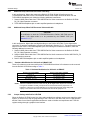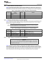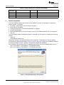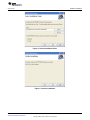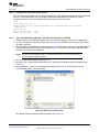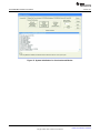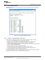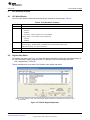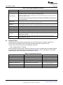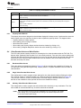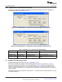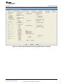
1
TVP5158 Evaluation Module
User's Guide
Literature Number: SLEU108
November 2009
2
SLEU108 – November 2009
Submit Documentation Feedback
Copyright © 2009, Texas Instruments Incorporated
1
2
3
4
5
6
7
8
9
10
......................................................................................................................... 6
1.1
Functional Overview .................................................................................................... 6
1.2
Notational Conventions ................................................................................................. 6
Board Level Description ....................................................................................................... 7
2.1
Analog Video/Audio Inputs ............................................................................................. 7
2.2
Analog Video/Audio Outputs ........................................................................................... 7
2.3
Digital Video/Audio Outputs to DaVinci HD EVM ................................................................... 8
2.4
Digital Video/Audio Cascade Output/Input ........................................................................... 8
2.5
I2C Configuration Options .............................................................................................. 8
2.6
Test Points and Jumpers ............................................................................................... 8
System Level Description ..................................................................................................... 9
Required Hardware and Equipment ..................................................................................... 10
Hardware Setup ................................................................................................................. 10
5.1
Setup for TVP5158EVM Stand-Alone Configuration .............................................................. 10
5.2
Setup for TVP5158EVM with DaVinci HD EVM ................................................................... 11
Software Installation .......................................................................................................... 14
TVP5158EVM Evaluation Procedures ................................................................................... 17
7.1
Stand-Alone Operation - Non-Interleaved Digital Video Output Modes ........................................ 17
7.2
Evaluation Using the DaVinci HD EVM ............................................................................. 19
7.3
Evaluation of Pixel-Interleaved Digital Video Output Modes ..................................................... 24
VCC Software in Depth ....................................................................................................... 25
8.1
VCC Main Window ..................................................................................................... 25
8.2
Register Map Editor ................................................................................................... 25
8.3
Property Sheets ........................................................................................................ 26
8.4
Video Decoder Select and Write Enables .......................................................................... 27
8.5
Example TVP5158 Property Pages ................................................................................. 28
Troubleshooting ................................................................................................................ 34
9.1
Troubleshooting Guide ................................................................................................ 34
TVP5158 EVM Schematics .................................................................................................. 38
Description
SLEU108 – November 2009
Submit Documentation Feedback
Table of Contents
Copyright © 2009, Texas Instruments Incorporated
3
www.ti.com
List of Figures
1
TVP5158 EVM Block Diagram ............................................................................................ 7
2
TVP5158EVM System Level Block Diagram ............................................................................ 9
3
Location of TVP5158EVM Video/Audio Inputs ........................................................................ 11
4
TVP5158EVM Software Setup Wizard
5
Select Installation Folder ................................................................................................. 15
6
Confirm Installation ........................................................................................................ 16
7
Installation Complete ...................................................................................................... 16
8
VCC Configuration
9
Specifying Cascaded Devices ........................................................................................... 18
10
USB Device Not Found Error Message ................................................................................ 18
11
Real-Time Polling Enable
12
VCC Main Window - Set for Communication to All Decoders ....................................................... 19
13
System Initialization for Analog Component YPbPr Video Output .................................................. 19
14
Browse to Command File
15
System Initialization for Line-Interleaved Modes ...................................................................... 22
16
mcvip_test Demo Application Menu
17
System Initialization for Pixel Interleave Modes ....................................................................... 24
18
TVP5158 Register Map Editor ........................................................................................... 25
19
VCC Main Window – Configured for Broadcast Write Access (default) ............................................ 28
20
VCC Main Window – Configured for Single Video Decoder Write Access ........................................ 28
21
TVP5158 Output Formatter Property Page With Decoder 1 Selected
30
22
TVP5158 Output Formatter Property Page With Decoder 4 Selected
31
23
24
25
26
27
28
29
30
31
32
33
34
4
.................................................................................
........................................................................................................
................................................................................................
................................................................................................
....................................................................................
.............................................
.............................................
TVP5158 Noise Reduction and Auto Contrast Property Page ......................................................
TVP5158 Audio Property Page (Seen Only When Decoder 1 is Selected) .......................................
TDM I2S Audio Data Configuration .....................................................................................
TVP5158 Video Format Property Page.................................................................................
THS8200 Input Controls / Status Property Page ......................................................................
Schematics (1 of 8)........................................................................................................
Schematics (2 of 8)........................................................................................................
Schematics (3 of 8)........................................................................................................
Schematics (4 of 8)........................................................................................................
Schematics (5 of 8)........................................................................................................
Schematics (6 of 8)........................................................................................................
Schematics (7 of 8)........................................................................................................
List of Figures
15
18
19
21
23
32
32
33
37
37
39
40
41
42
43
44
45
SLEU108 – November 2009
Submit Documentation Feedback
Copyright © 2009, Texas Instruments Incorporated
www.ti.com
List of Tables
1
TVP5158EVM Jumper Descriptions ...................................................................................... 8
2
Jumper Settings for Stand-Alone Configuration ....................................................................... 11
3
Hardware Modifcation for I2S Audio to DM6467 ...................................................................... 12
4
Jumper Settings for DaVinci HD EVM as TVP5158 I2C Master .................................................... 13
5
Jumper Settings for PC USB Interface as TVP5158 I2C Master
6
7
8
9
10
11
12
13
14
15
16
...................................................
Jumper Settings for a Cascaded TVP5158EVM ......................................................................
Recommended DM6467 Clock Frequencies ..........................................................................
VCC Main Menu Summary ...............................................................................................
VCC Register Map Editor Controls ......................................................................................
Property Sheet Controls ..................................................................................................
Property Sheet Button Controls .........................................................................................
Editing Tools vs Video Decoder Write Enables .......................................................................
Troubleshooting Setup and General Issues ...........................................................................
Troubleshooting with THS8200 and CompositeVideo Output .......................................................
Troubleshooting with DM6467 DaVinci HD EVM......................................................................
Troubleshooting I2C Connections and Cascaded EVMs.............................................................
SLEU108 – November 2009
Submit Documentation Feedback
List of Tables
Copyright © 2009, Texas Instruments Incorporated
13
14
19
25
26
26
27
28
34
34
35
35
5
User's Guide
SLEU108 – November 2009
TVP5158 Evaluation Module
1
Description
The TVP5158EVM evaluation module is a printed circuit board designed for evaluation of the TVP5158
Four-Channel PAL/NTSC Video Decoder. The TMS320DM6467 DVEVM (digital video evaluation module)
can be used with the TVP5158EVM as a back-end video processor. This user guide outlines the
necessary hardware and software setup required to provide full evaluation of the TVP5158.
1.1
Functional Overview
TVP5158EVM is powered by a single 5-V universal supply. The TVP5158EVM allows the user to have up
to four composite video inputs and up to four audio inputs. Analog YPbPr component video output is
supported for non-interleaved video modes. Digital video is output to the DaVinci HD EVM in a single or
dual ITU-R BT.656 configuration or in ITU-R BT.601 (16-Bit) configuration for evaluation of line-interleaved
modes.
The TVP5158EVM uses one PC USB port to provide I2C communication with the TVP5158, THS8200
Video/Graphics Triple DAC and the TLV320DAC32 Stereo Audio DAC devices on the TVP5158EVM. The
Video Control Center (VCC) application software is provided for control and evaluation of the
TVP5158EVM. A VT100 terminal program is required to connect to the DaVinci HD EVM via UART to
send Linux shell commands to control the DSP.
1.2
Notational Conventions
This document uses the following conventions.
The TMS320DM6467 Digital Video Evaluation Module is usually referred to as the DaVinci HD EVM.
The TMS320DM6467 Digital Media System-on-Chip is usually referred to as the DM6467.
6
TVP5158 Evaluation Module
SLEU108 – November 2009
Submit Documentation Feedback
Copyright © 2009, Texas Instruments Incorporated
Board Level Description
www.ti.com
2
Board Level Description
Figure 1 shows the various features available on the TVP5158EVM.
Figure 1. TVP5158 EVM Block Diagram
2.1
Analog Video/Audio Inputs
The TVP5158EVM makes use of all the available inputs on the TVP5158 decoder, including four CVBS
video inputs and four analog audio inputs. Connector J1 has four analog video (CVBS) inputs (yellow RCA
jacks) and four analog audio inputs (white RCA jacks).
2.2
Analog Video/Audio Outputs
The TVP5158EVM has a THS8200 Video/PC Graphics Triple DAC and a TLV320DAC32 audio DAC on
the board so that the user can evaluate video and audio performance using a single EVM setup. The
THS8200 Video/Graphics Triple DAC takes the video output from DVO port A of TVP5158 and outputs
analog YPbPr video signals to component output connector J4. The TLV320DAC32 Stereo Audio DAC
takes digital audio output from TVP5158 and outputs analog audio to the head phone jack J5.
SLEU108 – November 2009
Submit Documentation Feedback
TVP5158 Evaluation Module
Copyright © 2009, Texas Instruments Incorporated
7
Board Level Description
2.3
www.ti.com
Digital Video/Audio Outputs to DaVinci HD EVM
The TVP5158EVM has two dedicated connectors which match the digital video/audio input connectors on
the DaVinci HD EVM. Connector J9 includes a 16-bit video data bus (buffered data from DVO_A and
DVO_B of TVP5158), OCLK_P, OCLK_N, I2C and interrupts. The connector J10 includes BCLK, LRCLK
and SD_R/SD_M outputs from TVP5158. Samtec HQCD cables are required to connect TVP5158EVM
digital video and audio signals to the DaVinci HD EVM.
2.4
Digital Video/Audio Cascade Output/Input
The TVP5158EVM has two connectors for video/audio cascade mode test. The connector J2 is for
video/audio cascade output, which includes buffered data from the DVO_A and DVO_B video output ports
and audio cascade output from TVP5158. The connector J3 is for video/audio cascade input, which
includes video input data to the DVO_C and DVO_D video ports and audio cascade input from a lower
cascaded stage TVP5158 device.
2.5
I2C Configuration Options
The TVP5158EVM uses one PC USB port for I2C communication. The I2C bus master can be changed
based on jumper settings. Control is via the PCB USB interface (VCC application controls TVP5158), via
the DaVinci EVM (DSP driver software controls TVP5158) or via the cascade input/output connectors J3
or J2.
2.6
Test Points and Jumpers
Various test points are available on the TVP5158EVM for the user. This includes the various power
supplies as well as a few GND test points. The user can also use J2/J3 for primary test-point headers to
access video/audio data, video/audio clocks, I2C and GND.
There are several jumpers available on the TVP5158EVM that configure I2C address select, I2C control
configuration, clock source selection and I2S source select. Each jumper is set by default in its preferred
state for the TVP5158EVM. Next to each jumper on the TVP5158EVM is the silkscreen that describes the
various jumper configurations. If the I2C address is changed on the TVP5158EVM while the
TVP5158EVM is powered up, then that device will not recognize the new I2C address. The reset button
on the TVP5158EVM must be pressed and the VCC application must be exited, restarted, and
re-configured for the new I2C address. Table 1 shows the TVP5158EVM jumper settings.
Table 1. TVP5158EVM Jumper Descriptions
Jumper
Designator
Description of Function
Default
TVP5158 I2C address selection (I2C_A0)
W0
1-2
1-2: Low
2-3: High
TVP5158 I2C address selection (I2C_A1)
W1
1-2
1-2: Low
2-3: High
TVP5158 I2C address selection (I2C_A2)
W2
1-2
1-2: Low
2-3: High
I2C SDA source selection
W3
1-2: USB controls I2C
2-3: DaVinciHD controls I2C
OFF: Control by another EVM for cascade mode.
1-2
I2C SCL source selection
W4
8
1-2: USB controls I2C
2-3: DaVinciHD controls I2C
OFF: Control by another EVM for cascade mode.
TVP5158 Evaluation Module
1-2
SLEU108 – November 2009
Submit Documentation Feedback
Copyright © 2009, Texas Instruments Incorporated
System Level Description
www.ti.com
Table 1. TVP5158EVM Jumper Descriptions (continued)
Jumper
Designator
Description of Function
Default
Clock source selection
W5
W6
1-2
1-2: Crystal
2-3: Clock from another EVM for cascade mode
I2C EEPROM
ON
ON: Use EEPROM (MUST ALWAYS BE ON)
W7
I2C SCL connection for audio DAC
ON
W8
I2C SDA connection for audio DAC
ON
I2S input selection for audio DAC
W9
3
2-3
1-2: TVP5158 mixing output to audio DAC (SD_M)
2-3: TVP5158 record output to audio DAC (SD_R)
System Level Description
The system block diagram illustrated in Figure 2 provides an example of how the TVP5158EVM may be
used for evaluation. Typically, the analog video/audio input is provided by a video source such as a
pattern generator or a DVD player running a test DVD. The TVP5158EVM is configured with the 5-V
supply and the USB cable provided.
The TVP5158EVM analog video output is standard definition component video (YPbPr). These outputs
are then fed into a high-end or studio-quality NTSC/PAL monitor.
The user can also connect the TVP5158EVM to a DaVinci HD EVM and then output combined video from
the DaVinci HD EVM to a 1080i HD monitor.
Figure 2. TVP5158EVM System Level Block Diagram
SLEU108 – November 2009
Submit Documentation Feedback
TVP5158 Evaluation Module
Copyright © 2009, Texas Instruments Incorporated
9
Required Hardware and Equipment
4
www.ti.com
Required Hardware and Equipment
The required hardware and equipment are as follows:
• Windows-based PC with Windows XP or later
• Video sources (security camera, pattern generator, DVD player, etc.)
• Display monitor that supports
– 1080i component YPbPr video (50 and 60 Hz)
– 480i and 576i component YPbPr video
• Audio amplifier/speakers or headphones
• TVP5158EVM (provided)
– Cables to provide up to four composite video and up to four audio line inputs
– Component Video (YPbPr) cable for output
– USB cable (provided)
– Universal 5-V power supply (100 to 240 VAC in, 5 VDC/3.0 A out) (provided)
• DaVinci HD EVM
– Two Samtec HQCD cables
– Component video (YPbPr) cable for output
– RS-232 null MODEM cable
– Universal 5-V power supply (100 to 250 VAC in, 5 VDC/5.0 A out)
5
Hardware Setup
The following sections describe the hardware setup for evaluation of the TVP5158.
5.1
Setup for TVP5158EVM Stand-Alone Configuration
For evaluation of video quality, comb filter, noise reduction, auto-contrast and other features, the
TVP5158EVM can be setup in a stand-alone configuration. Analog video and audio sources are input to
TVP5158. TVP5158 outputs digital video as ITU-R BT.656 or ITU-R BT.601 non-interleaved video to the
THS8200 PC Graphics/Video Triple DAC. Component Video YPbPr from the THS8200 is output in 480i or
576i format to a video monitor. To setup the stand-alone configuration, make the following connections:
1. Analog video sources to TVP5158EVM composite video inputs (see Figure 3)
2. Analog audio sources to TVP5158EVM audio line inputs (see Figure 3)
3. Analog component YPbPr video out from TVP5158EVM to video monitor
4. Stereo audio headphone output from TVP5158EVM to audio amplifier/speakers or headphones
5. USB cable from PC to TVP5158EVM. A green LED should be lit indicating that the EVM is ready for
communication on the USB.
6. 5-V power supply to the dc jack on the TVP5158EVM
10
TVP5158 Evaluation Module
SLEU108 – November 2009
Submit Documentation Feedback
Copyright © 2009, Texas Instruments Incorporated
Hardware Setup
www.ti.com
Video Inputs
Audio Inputs
CH2
CH4
CH2
CH4
CH1
CH3
CH1
CH3
Figure 3. Location of TVP5158EVM Video/Audio Inputs
Table 2. Jumper Settings for Stand-Alone Configuration
Jumper
Designator
W2, W1, W0
Setting
TVP5158 I2C address
selection
1-2, 1-2, 1-2
Comment
Slave address 0xB0 (1011 LLL0)
W3, W4
I2C master selection
1-2, 1-2
PC USB port controls TVP5158 I2C
W7, W8
I2C connection to audio DAC
ON, ON
Connected
W9
5.2
Function
I2S selection to audio DAC
2-3 or 1-2
Monitor record I2S output or mixer I2S output from TVP5158
Setup for TVP5158EVM with DaVinci HD EVM
The TMS320DM6467 DVEVM (digital video evaluation module) can be used as the audio/video back-end
processor for evaluation of TVP5158. This EVM is available separately from Texas Instruments and is
referred to as the DaVinci HD EVM in this document.
This configuration allows evaluation of all line-interleaved video output formats with up to four channels in
D1, Half-D1 or CIF resolution. Eight-channel line-interleaved video is also possible if two TVP5158EVM
boards are cascaded together.
Sample video and audio driver code and a demo application are provided to run on the TMS320DM6467
on the Linux O/S.
To
1.
2.
3.
4.
setup the TVP5158EVM with DaVinci HD EVM configuration, make the following connections:
Analog video sources to TVP5158EVM composite video inputs (see Figure 3)
Analog audio sources to TVP5158EVM audio line inputs (see Figure 3)
Analog component YPbPr video out from DaVinci HD EVM to monitor
USB cable from PC to TVP5158EVM. A green LED should be lit indicating that the EVM is ready for
communication on the USB.
NOTE: If the VCC GUI Software for TVP5158 is not used, it is not necessary to connect the
TVP5158EVM to a PC USB port.
5.
6.
7.
8.
RS-232 null MODEM cable from PC to DaVinci HD EVM
5-V power supply to the dc jack on the TVP5158EVM
5-V power supply to the dc jack on the DaVinci HD EVM
Ethernet cable from LAN to DaVinci HD EVM
SLEU108 – November 2009
Submit Documentation Feedback
TVP5158 Evaluation Module
Copyright © 2009, Texas Instruments Incorporated
11
Hardware Setup
5.2.1
www.ti.com
Additional Setup when DSP Processes Video Only
In this configuration, digital video goes to the DaVinci HD EVM. Digital I2S audio goes to the
TLV320DAC32 Audio DAC on the TVP5158EVM. Stereo audio output can then be taken from the
TVP5158EVM headphone jack. Make the following additional connections:
1. Samtec HQCD ribbon cable from TVP5158EVM DaVinci Video connector to the DaVinci HD EVM
DC_P2 Video Expansion connector.
2. TVP5158EVM headphone jack to audio amplifier/speakers or headphones
5.2.2
Additional Setup When DSP Processes Video and Audio
CAUTION
A modification to both the TVP5158EVM and the DaVinci HD EVM must be
made if I2S digital audio is to be processed by the DM6467 DSP (see
Section 5.2.2.1).
In this configuration, digital video and digital audio go to the DaVinci HD EVM. For the digital audio
connection, a hardware modification is required as described in Section 5.2.2.1. The stereo audio is then
output from the DaVinci HD EVM headphone jack. After making the hardware modification, make the
following additional connections:
1. Samtec HQCD ribbon cable from TVP5158EVM DaVinci Video connector to the DaVinci HD EVM
DC_P2 Video Expansion connector
2. Samtec HQCD ribbon cable from TVP5158EVM DaVinci Audio connector to DaVinci HD EVM DC_P3
I/O Expansion connector
3. DaVinci HD EVM headphone jack to audio amplifier/speakers or headphones
5.2.2.1
Hardware Modification for I2S Audio to DM6467 DSP
Three 0-Ω resistors must be removed from the TVP5158EVM and three 0-Ω resistors must be removed
from the DaVinci HD EVM according to Table 3.
Table 3. Hardware Modifcation for I2S Audio to DM6467
Remove From TVP5158EVM
Remove From DaVinci HD EVM
R42 SD_M
R13 MCASP0_ACLKR
R98 MCASP0_EN
R17 MCASP0_AFSR
R99 AUDIO_CLK_EN
R31 MCASP0_AXR1
NOTE: After this modification has been made, the SD_M I2S digital audio output from TVP5158 will
no longer be available. The SD_R output must be used and W9 must be jumpered 2-3. If
headphone output from the TVP5158EVM is to be tested using the audio mixer (SD_M I2S
output), 0-ohm resistor R42 must be reinstalled and W9 must be jumpered 1-2.
5.2.3
Jumper Settings with DaVinci HD EVM
When the DaVinci HD EVM is used, the video and/or audio driver software can be set to control the entire
system, or can be set to skip I2C programming of the TVP5158. In the latter case, the PC USB interface
and the Video Control Center application software are used to initialize and experiment with TVP5158
register settings through a graphical user interface.
12
TVP5158 Evaluation Module
SLEU108 – November 2009
Submit Documentation Feedback
Copyright © 2009, Texas Instruments Incorporated
Hardware Setup
www.ti.com
5.2.3.1
DaVinci HD EVM as TVP5158 I2C Master
Table 4 describes the jumper settings to set the DaVinci HD EVM as I2C master for the TVP5158. In this
case, the Linux application and driver software control the entire system. Audio can be output from the
TVP5158EVM or from the DaVinci HD EVM. See Section 5.2.1 and Section 5.2.2 for audio configurations.
Table 4. Jumper Settings for DaVinci HD EVM as TVP5158 I2C Master
Jumper
Designator
W2, W1, W0
Setting
TVP5158 I2C Address
selection
1-2, 1-2, 1-2
Comment
Slave address 0xB0 (1011 LLL0)
W3, W4
I2C master selection
2-3, 2-3
DaVinci HD EVM controls TVP5158 I2C
W7, W8
I2C connection to audio DAC
ON, ON
Connected
W9
5.2.3.2
Function
I2S selection to audio DAC
2-3 or 1-2
Monitor record I2S output or mixer I2S output from TVP5158
PC USB as TVP5158 I2C Master with DaVinci HD EVM
Table 5 describes the jumper settings to set the PC USB interface as I2C master for the TVP5158. In this
case, the Video Control Center application software can be used to experiment with TVP5158 register
settings through a graphical user interface.
NOTE: This system configuration has known I2C issues that sometimes occur when PC USB and
DaVinci HD EVM I2C buses are used independently.
Table 5. Jumper Settings for PC USB Interface as TVP5158 I2C Master
Jumper
Designator
W2, W1, W0
Setting
TVP5158 I2C address
selection
W3, W4
I2C master selection
W7, W8
I2C connection to audio DAC
W9
5.2.3.3
Function
I2S selection to audio DAC
1-2, 1-2, 1-2
Comment
Slave address 0xB0 (1011 LLL0)
1-2, 1-2
PC USB port controls TVP5158 I2C
ON, ON
Connected
2-3 or 1-2
Monitor record I2S output or mixer I2S output from TVP5158
Jumper Settings for Audio/Video Cascade Configuration
CAUTION
If two or more TVP5158EVM boards are cascaded together, care must be
taken that the leads on the J2 and J3 connectors are in alignment, because the
connectors are not keyed.
Table 6 describes the jumper settings for a second stage TVP5158EVM connected for video/audio
cascade operation. In this case, the I2C slave address must be set be set differently than the first EVM.
The I2C Master jumpers must be removed to allow the first stage EVM to control I2C (either from USB or
from DaVinci HD EVM). USB should be connected to the first stage EVM if used. The Audio DAC I2C
must be disconnected on the second stage, since they are both at the same I2C slave address.
SLEU108 – November 2009
Submit Documentation Feedback
TVP5158 Evaluation Module
Copyright © 2009, Texas Instruments Incorporated
13
Software Installation
www.ti.com
Table 6. Jumper Settings for a Cascaded TVP5158EVM
Jumper
Designator
W2, W1, W0
TVP5158 I2C address selection
Setting
1-2, 1-2, 2-3
Comment
Slave address 0xB2 (1011 LLH0)
W3, W4
I2C master selection
OFF, OFF
Stage 1 TVP5158EVM controls TVP5158 I2C
W7, W8
I2C connection to audio DAC
OFF, OFF
Disconnected
W9
6
Function
I2S selection to audio DAC
2-3
Not used
Software Installation
If the TVP5158EVM Software has previously been installed on the PC, it is necessary to uninstall the
previous version. To uninstall:
1. Click Start > Control Panel > Add or Remove Programs.
2. Wait for the list to populate.
3. Scroll down and click on "TVP5158EVM Software" to highlight it.
4. Click the remove button.
5. When prompted with Are you sure you want to remove TVP5158EVM Software from your computer?,
click Yes.
The TVP5158EVM software installation program is contained in a ZIP archive file containing the following
two files:
Setup.exe
TVP5158EVM_Software.msi
Unzip these two files to a temporary directory and run setup.exe. The dialog box in Figure 4 appears.
Click Next on the dialog boxes shown in Figure 4, Figure 5, and Figure 6. When the installation is finished,
the dialog box shown in Figure 7 appears. Click Close to complete the installation.
Documentation and a shortcut to the VCC application can now be found in the Windows start menu at:
Start > All Programs > TVP5158EVM > TVP5158EVM Software
Start > All Programs > TVP5158EVM > TVP5158EVM User Guide
Figure 4. TVP5158EVM Software Setup Wizard
14
TVP5158 Evaluation Module
SLEU108 – November 2009
Submit Documentation Feedback
Copyright © 2009, Texas Instruments Incorporated
Software Installation
www.ti.com
Figure 5. Select Installation Folder
Figure 6. Confirm Installation
SLEU108 – November 2009
Submit Documentation Feedback
TVP5158 Evaluation Module
Copyright © 2009, Texas Instruments Incorporated
15
Software Installation
www.ti.com
Figure 7. Installation Complete
16
TVP5158 Evaluation Module
SLEU108 – November 2009
Submit Documentation Feedback
Copyright © 2009, Texas Instruments Incorporated
TVP5158EVM Evaluation Procedures
www.ti.com
7
TVP5158EVM Evaluation Procedures
7.1
Stand-Alone Operation - Non-Interleaved Digital Video Output Modes
The following is the procedure for evaluation of TVP5158 for non-interleaved modes. The digital video
output from TVP5158 is converted to analog component YPbPr video using a THS8200 Video/PC
Graphics Triple DAC:
1. Double-click the TVP5158EVM Software icon on the Windows desktop to start the VCC application.
2. The VCC Configuration dialog box appears (see Figure 8). Click OK to continue.
3. The Cascaded Devices dialog box appears (see Figure 9). Click OK to continue. If a message appears
indicating that the USB device was not found (see Figure 10), disconnect the USB cable, wait three
seconds and reconnect the USB cable.
4. After 3 to 5 seconds, the Real-Time Polling dialog box appears (see Figure 11). Click OK to continue.
5. The VCC main window appears (see Figure 12).
6. Set video source(s) to the NTSC video standard (for this example).
7. Click the Tools > System Initialization menu item. The System Initialization dialog box (see Figure 13)
appears. Click once on the following table entry:
TVP5158 + THS8200, NTSC, Non-Interleaved, 1-Ch D1, Quad BT.656 @ 27 MHz
Click the PROGRAM button. The TVP5158 is now programmed for the NTSC standard using the
above video output format. The output formatter is bypassed.
8. To select a video input:
(a) In the VCC main window, select the video decoder for the video input to be displayed. This will
select which source is used to detect the video standard for updating THS8200 register settings.
(b) In System Initialization table, click once on one of the following table entries to the select the video
channel to be displayed and click the Program button.
Select Ch-1 Video Input
Select Ch-2 Video Input
Select Ch-3 Video Input
Select Ch-4 Video Input
9. Video from the selected video input should now be seen on the monitor and audio channels 1 and 2
should be heard from the left and right speakers respectively.
Figure 8. VCC Configuration
SLEU108 – November 2009
Submit Documentation Feedback
TVP5158 Evaluation Module
Copyright © 2009, Texas Instruments Incorporated
17
TVP5158EVM Evaluation Procedures
www.ti.com
Figure 9. Specifying Cascaded Devices
Figure 10. USB Device Not Found Error Message
Figure 11. Real-Time Polling Enable
18
TVP5158 Evaluation Module
SLEU108 – November 2009
Submit Documentation Feedback
Copyright © 2009, Texas Instruments Incorporated
TVP5158EVM Evaluation Procedures
www.ti.com
Figure 12. VCC Main Window - Set for Communication to All Decoders
Figure 13. System Initialization for Analog Component YPbPr Video Output
7.2
7.2.1
Evaluation Using the DaVinci HD EVM
Setting DM6467 ARM and DDR2 Memory Clock Rates
For maximum performance, in a system using DM6467 and TVP5158(s) in the line-interleaved video
modes, the DM6467 clock frequencies should be set as specified in Table 7.
Table 7. Recommended DM6467 Clock Frequencies
ARM Clock
675 MHz
DDR2 Memory Clock
324 MHz (1)
(1)
DaVinci HD EVM assembly revision F or later is required.
SLEU108 – November 2009
Submit Documentation Feedback
TVP5158 Evaluation Module
Copyright © 2009, Texas Instruments Incorporated
19
TVP5158EVM Evaluation Procedures
www.ti.com
Since the DaVinci HD EVM is not packaged with the TVP5158, it is usually necessary to program its
NAND flash memory to the recommended clock frequencies, as described by the following procedure:
1. Unzip the UBL_DM646x_NAND_675_324.zip archive file onto the PC’s local hard drive.
Suggested location is C:\UBL
2. Connect a null MODEM 9-pin serial cable from the DaVinci HD EVM UART connector to the PC COM1
serial port.
3. Close any open program that is using the COM1 serial port.
4. Turn OFF the DaVinci HD EVM power switch.
5. Set SW3 Boot Mode Configuration positions 1-3 to OFF and position 4 to ON to select UART0 Flash
Boot. SW3 is located beneath the Samtec HQCD digital video ribbon cable. In the OFF position, the
switch is moved toward the PCI connector.
6. In the Windows Start menu, click Run, type cmd, and click OK to open a command window.
7. Execute these commands in the command window:
cd \ubl
sfh_DM646x.exe -nandflash UBL_DM646x_NAND_675_324.bin u-boot.bin
8. After the Waiting for the DM646x... message appears in the terminal window, turn ON the DaVinci HD
EVM power switch.
9. After flash programming has completed, turn OFF the DaVinci HD EVM power switch. Set the SW3
Boot Mode Configuration positions 1-3 to ON and position 4 to OFF to select NAND Flash boot mode.
7.2.2
Evaluation Procedure for Line-Interleaved Video Output Modes
The following are the instructions for evaluation of TVP5158 for line-interleaved modes. The digital video
output from TVP5158 is captured using a DM6467 DaVinci HD EVM and is demultiplexed and displayed
on a 1080i HD monitor.
7.2.2.1
DaVinci HD EVM Boot
1. Start the VT100 terminal application of your choice. For example, HyperTerminal can be started in
Windows XP using these steps:
(a) Click Start > All Programs > Accessories > Communications > HyperTerminal.
Set "Connect using" to:
COM1 (or other available serial port)
Set "Port Settings" to:
Bits per second: 115200
Data bits: 8
Parity: None
Stop bits: 1
Flow control: None
2. Turn ON the DaVinci HD EVM power switch. It may be necessary to halt the boot process (by striking
a key at the terminal) to modify boot parameters (especially the first time). For details of the boot
methods see separate documentation that is provided with the DaVinci HD EVM: TMS320DM6467
DVEVM Getting Started Guide (SPRUF88).
NOTE: See the mcvip_tvp5158\README.TXT file for instructions on running or building target
image and application. This is found in the zip file containing the DaVinci HD video/audio
driver source code.
20
TVP5158 Evaluation Module
SLEU108 – November 2009
Submit Documentation Feedback
Copyright © 2009, Texas Instruments Incorporated
TVP5158EVM Evaluation Procedures
www.ti.com
7.2.2.2
Setup DaVinci HD Video / Audio Drivers
Once the DaVinci HD EVM boot has completed, the login: prompt appears at the terminal. Copy and paste
the Linux commands below to set up the video capture and and audio driver software. In place of
<program_directory>, insert the directory path where the driver files are stored.
root
cd <program_directory>
insmod cmemk.ko phys_start=0x87800000 phys_end=0x8ba00000 pools=1x1000
./mapdmaq-hd
insmod drv.ko
mknod /dev/dev_i2c c 251 0
mknod /dev/dev_dma c 250 0
7.2.2.3
Start VCC Application (Optional – Provides GUI Interface for TVP5158)
1. Double-click the TVP5158EVM Software icon on the Windows desktop to start the VCC application.
2. The VCC Configuration dialog box appears (see Figure 8). Set THS8200 device family to NOT USED.
Click OK to continue.
3. The Cascaded Devices dialog box appears (see Figure 9). Click OK to continue. If a message appears
indicating that the USB device was not found (see Figure 10), disconnect the USB cable, wait three
seconds, and reconnect the USB cable.
NOTE: If a second TVP5158EVM is used for cascade operation select "2 Devices Cascaded" and
I2C slave addresses 0xB0 and 0xB2.
4. The VCC main window appears (see Figure 12).
5. Click the Tools > System Initialization menu item. The System Initialization dialog box appears (see
Figure 13).
6. Click the Browse… button. The Open dialog box appears (see Figure 14). Double-click the file
TVP5158EVM_DaVinci_HD_Setup.CMD
Figure 14. Browse to Command File
The dataset descriptions table should now appear (see Figure 15).
SLEU108 – November 2009
Submit Documentation Feedback
TVP5158 Evaluation Module
Copyright © 2009, Texas Instruments Incorporated
21
TVP5158EVM Evaluation Procedures
www.ti.com
Figure 15. System Initialization for Line-Interleaved Modes
22
TVP5158 Evaluation Module
SLEU108 – November 2009
Submit Documentation Feedback
Copyright © 2009, Texas Instruments Incorporated
TVP5158EVM Evaluation Procedures
www.ti.com
7.2.2.4
mcvip_test Demo Application
The syntax and main menu of the mcvip_test (multi-channel video interface port) demo application is
shown in Figure 16.
Figure 16. mcvip_test Demo Application Menu
7.2.2.5
Procedure for Initializing Individual Video Formats
The procedure for initializing the system for each individual video output format is as follows:
1. Start the mcvip_test application (do not enter the menu option yet).
Example: ./mcvip_test.out NTSC VCC <Cascade Mode Option> <Audio Mode Option>
2. Program TVP5158 for the video output format (only if using VCC GUI Software).
In the VCC System Initialization window, click on the video output format (same format as chosen in
step 3) and click the PROGRAM button.
3. Select the video capture format for the DaVinci HD EVM:
In terminal window, type video format menu option (00-1b) and then <Enter>.
The video output should now be displayed on the HD video monitor using 1080i format.
4. At Linux terminal, type 0 <return> to stop the video capture.
5. Audio should be heard from the left and right speakers respectively if audio mode option selected.
Repeat steps 1 through 4 for each line-interleaved video output format.
SLEU108 – November 2009
Submit Documentation Feedback
TVP5158 Evaluation Module
Copyright © 2009, Texas Instruments Incorporated
23
TVP5158EVM Evaluation Procedures
7.3
www.ti.com
Evaluation of Pixel-Interleaved Digital Video Output Modes
The TVP5158EVM can be programmed for pixel-interleaved modes as described below. The DM6467
DaVinci HD EVM does not support pixel interleave modes, so a different back-end processor is required
for this evaluation.
1. In the VCC System Initialization dialog box, click the Browse button. The Open dialog box shown in
Figure 14 appears. Double-click the following file:
TVP5158EVM_Pixel_Interleave_Setup.CMD
2. The dataset descriptions table should now appear as shown in Figure 17. Click once on the following
table entry:
Multi-Standard, Pixel-Interleave, 2-Ch D1, 8-bit @ 54MHz (OCLK_P, OCLK_N @ 27MHz, Opposite
Phase)
Click the PROGRAM button. The TVP5158 is now programmed to automatically detect the video
standard received at the input and output video in the above pixel-interleaved format.
Figure 17. System Initialization for Pixel Interleave Modes
24
TVP5158 Evaluation Module
SLEU108 – November 2009
Submit Documentation Feedback
Copyright © 2009, Texas Instruments Incorporated
VCC Software in Depth
www.ti.com
8
VCC Software in Depth
8.1
VCC Main Window
The VCC main window contains the menu bar whose contents are summarized in Table 8.
Table 8. VCC Main Menu Summary
Menu
Contents
File
Exit
Edit
Register Map – Edit I2C registers directly
TVP5158
THS8200
Generic I2C – Edit I2C registers for any slave address
Property Sheets – GUI controls for the I2C register map
TVP5158
THS8200
Tools
System Initialization – Initializes system using .CMD files
Real-time Polling – Enables update of THS8200 when a video standard change occurs
USB/LPT/I2C Options – Set 100 or 400 kHz I2C
8.2
Window
Allows selection of the active window
Help
Displays program version
Register Map Editor
The register map editor (see Figure 18) allows the display and editing of the entire used register space of
the TVP5158 within a simple scrolling text box. To open this, click on the following menu item:
Edit > Register Map > TVP5158
Table 9 describes how to use each of the controls in the register map editor.
NOTE: To save registers to a file, check the Histogram Enable checkbox and click Read All. Click Show to view
the saved file.
Figure 18. TVP5158 Register Map Editor
SLEU108 – November 2009
Submit Documentation Feedback
TVP5158 Evaluation Module
Copyright © 2009, Texas Instruments Incorporated
25
VCC Software in Depth
www.ti.com
Table 9. VCC Register Map Editor Controls
Control
Register Window
Definition
Scrolling text box that displays the address and data for the I2C registers that are defined for the device.
This contains the I2C subaddress that will be accessed using the Write and Read buttons. Clicking on a
row selects an address, which then appears in the address edit box.
Address Edit Box
NOTE: After clicking on a row, the Data Edit box contains the data that was in the register window. The
device has not yet been read.
The address up/down arrows are used to jump to the next/previous subaddress that is defined for the
device. If an address is not defined for the device, then it can still be accessed by typing the subaddress
in the Address Edit box.
Data Edit Box
Write Button
This contains the data which will be written to or was read from the I2C subaddress.
The data up/down arrows increment/decrement the data value by 1.
Writes the byte in the Data Edit box to the address in the Address Edit box.
The I2C register is written to whether or not the data is different from the last time the register was read.
Read Button
Reads the data from the address in the Address Edit box into the Data Edit box and the register window.
Read All Button
Reads all defined readable registers from the device and updates the register window.
Hex Button
Converts all values in the register window and address and data edit boxes to hexadecimal.
Dec Button
Converts all values in the register window and address and data edit boxes to decimal.
Closes the dialog.
Close Button
Loop Count
8.3
NOTE: Multiple edit register map windows can be open at the same time (one for each device). Use the
Window menu to navigate.
Causes subsequent write, read or read all operations to be performed N times. N is entered as a
decimal number from 1 to 999.
Property Sheets
The property sheets represent the register data in a user-friendly format. The data is organized by
function, with each function having its own page and being selectable via tabs at the top.
To open this for the TVP5158, click on the following menu item:
Edit > Property Sheets > TVP5158
When the property sheet function is started or whenever you tab to a different page, all readable registers
in the device are read from hardware to initialize the dialog pages. Values on the page are changed by
manipulating the various dialog controls as described in Table 11.
Table 10. Property Sheet Controls
Type of Control
26
Function/How to Set a Value
When is Hardware Updated?
Read-Only Edit Box
Read status information
N/A
Check Box
Toggle a single bit
After Apply
Drop-Down List
Select from a text list
After Apply
Edit Box
Type a number
After Apply
Edit Box with Up/Down Arrows
Use up/down arrows or type a number
Up/Down Arrows: Immediately
Type a number: After Apply
Slider
Slide a lever
Immediately
Pushbutton
Initiate an action
Immediately
TVP5158 Evaluation Module
SLEU108 – November 2009
Submit Documentation Feedback
Copyright © 2009, Texas Instruments Incorporated
VCC Software in Depth
www.ti.com
Table 11. Property Sheet Button Controls
Button
8.3.1
Definition
OK
Writes to all writeable registers whose data has changed. A register is flagged as changed if the value to be
written is different from the value last read from that address.
Closes the dialog.
Cancel
Causes all changes made to the property page since the last Apply to be discarded. Changes made to dialog
controls with 'immediate hardware update' are not discarded, because they have already been changed in
hardware.
Does not write to hardware.
Closes the dialog.
Apply
Writes to all writeable registers whose data has changed. A register is flagged as changed if the value to be
written is different from the value last read from that address.
Does not close the dialog.
Property Sheet Refresh
The property sheets were designed so that the data displayed is always current. Certain actions cause the
entire register map to be read from the device and to update the property sheets. This happens when:
• Property sheets are initially opened.
• When tabbing from one page to another.
• When Read All is clicked.
• When making the Property Sheets window the active window (by clicking on it).
• When making a Register Map Editor window the active window (by clicking on it).
8.4
Video Decoder Select and Write Enables
The VCC main window contains controls for accessing the four video decoders within the TVP5158. The
buttons under “Selected Video Decoder Core” are mutually exclusive. Four sets of the various editing tools
(Register Map Edit and Property Sheets) exist in memory, but only the data for the selected video decoder
can be seen. Any or all of the write enable buttons can be enabled. These control which of the video
decoders will accept I2C writes.
8.4.1
Broadcast Write Access
This is the default configuration as shown in Figure 19. All four decoders are enabled for I2C writes. All
I2C writes done using the Edit Register Map, Property Sheets, or System Initialization tools will affect all
video decoders.
8.4.2
Single Video Decoder Write Access
This configuration is used to program unique settings for one video decoder without effecting the others.
The “Set write enable for selected decoder only” check box should be checked as shown in Figure 20.
This provides a shortcut, so that as each decoder is selected using the decoder buttons, the same
decoder is also enabled for writes (and the other three are disabled for writes).
8.4.3
Arbitrary Video Decoder Write Access
This configuration is used to program the write enabled video decoder(s) in any combination. The “Set
write enable for selected decoder only” check box should be unchecked.
NOTE: The command files used by the System Initialization tool can override the write enable
button settings. They are generally setup for writing to all decoders independent of the
current write enable buttons setting.
SLEU108 – November 2009
Submit Documentation Feedback
TVP5158 Evaluation Module
Copyright © 2009, Texas Instruments Incorporated
27
VCC Software in Depth
8.4.4
www.ti.com
Editing Tools vs Video Decoder Write Enables
The behavior of the System Initialization, Edit Register Map and Property Sheets tools regarding the
decoder write enables is described in Table 12.
Figure 19. VCC Main Window – Configured for Broadcast Write Access (default)
Figure 20. VCC Main Window – Configured for Single Video Decoder Write Access
Table 12. Editing Tools vs Video Decoder Write Enables
8.5
Editing Tool
Reads From
Writes To
Writes What
Command File
N/A
Write Enabled decoders
(can be overridden in cmd file)
I2C register values
Edit Register Map
Selected Decoder
Write Enabled decoders
1 byte – same data to all
Edit Property Sheets
Selected Decoder
Write Enabled decoders
Bit fields that changed on the selected
decoder
Example TVP5158 Property Pages
Example property pages are shown in Figure 21 through Figure 24.
Some of the controls for the Output Formatter (OFM) page only exist for video decoder 1. Figure 21
shows the OFM page when Decoder 1 is the selected decoder. Figure 22 shows the OFM page when
Decoder 4 is the selected decoder (some of the OFM controls are not visible). They would also not be
visible for Decoder 2 and Decoder 3. To change the Port A selection, for example, Decoder 1 must be the
selected decoder.
The Audio property page only exists for video decoder 1. To access the Audio controls Decoder 1 must be
the selected decoder.
28
TVP5158 Evaluation Module
SLEU108 – November 2009
Submit Documentation Feedback
Copyright © 2009, Texas Instruments Incorporated
VCC Software in Depth
www.ti.com
Figure 21. TVP5158 Output Formatter Property Page With Decoder 1 Selected
SLEU108 – November 2009
Submit Documentation Feedback
TVP5158 Evaluation Module
Copyright © 2009, Texas Instruments Incorporated
29
VCC Software in Depth
www.ti.com
Figure 22. TVP5158 Output Formatter Property Page With Decoder 4 Selected
30
TVP5158 Evaluation Module
SLEU108 – November 2009
Submit Documentation Feedback
Copyright © 2009, Texas Instruments Incorporated
VCC Software in Depth
www.ti.com
Figure 23. TVP5158 Noise Reduction and Auto Contrast Property Page
SLEU108 – November 2009
Submit Documentation Feedback
TVP5158 Evaluation Module
Copyright © 2009, Texas Instruments Incorporated
31
VCC Software in Depth
www.ti.com
Figure 24. TVP5158 Audio Property Page (Seen Only When Decoder 1 is Selected)
32
TVP5158 Evaluation Module
SLEU108 – November 2009
Submit Documentation Feedback
Copyright © 2009, Texas Instruments Incorporated
VCC Software in Depth
www.ti.com
Figure 25 shows how TDM I2S audio data can be configured. Jumper W9 can be used to select the SD_R
(default) or SD_M I2S output to the audio DAC.
Figure 25. TDM I2S Audio Data Configuration
SLEU108 – November 2009
Submit Documentation Feedback
TVP5158 Evaluation Module
Copyright © 2009, Texas Instruments Incorporated
33
Troubleshooting
9
www.ti.com
Troubleshooting
This section discusses ways to troubleshoot the TVP5158EVM.
9.1
Troubleshooting Guide
If you are experiencing problems with the TVP5158EVM hardware or the VCC software, see Table 13
through Table 16 for available solutions.
Table 13. Troubleshooting Setup and General Issues
Symptom
Cause
Solution
TVP5158EVM Software
Installer reports that
previous version must
be uninstalled
Previous version was
installed
Use "Add or Remove Programs" in Windows Control Panel to remove
previous version of TVP5158EVM Software. Run SETUP.EXE again.
On connecting USB
cable, green "connected
LED" does not light.
EVM was not
recognized on the USB.
Disconnect USB cable between PC and EVM. Wait 3 seconds. Reconnect the
USB cable. Green "connected LED" near USB connector should light.
On connecting USB
cable, New Hardware
Wizard appears
Jumper W6 has been
removed.
Install jumper W6 near USB connector. Disconnect USB cable between PC
and EVM. Wait 3 seconds. Reconnect the USB cable. Green "connected
LED" should light.
VCC application has
slow response time.
USB polling rate is too
slow.
Conect EVM directly to a laptop/desktop USB port instead going through a
docking station. Property Pages can not be refreshed using Read All buttons
at more than about a 1-Hz rate.
Nothing seems to
happen when I click
Read All repeatedly.
Clicking Read All button
too frequently.
Property Pages can not be refreshed using Read All buttons at more than
about a 1-Hz rate.
Table 14. Troubleshooting with THS8200 and CompositeVideo Output
Symptom
Cause
Solution
USB: Device Not Found
error message
EVM was not
recognized on the USB.
Disconnect USB cable. Wait 3 seconds. Reconnect USB cable. Green
"connected LED" should light. Click continue
USB: I2C Error Code 1
error message. An I2C
acknowledge error has
occurred. See reported
I2C slave address and
sub-address.
5V power not present
Connect 5V power supply to EVM. Click Continue.
EVM hardware reset
button has been
pressed.
Normal occurrence. An I2C error will occur if the hardware reset button is
pressed while real-time polling or property page auto-update is active. Click
Continue.
I2C slave address
jumper setting and
program setting do not
match.
Check that jumpers W2, W1 and W0 are connected across pins 1-2 (L, L, L)
to specify slave address 0xB0 (Set jumper W0 across pins 2-3 (L, L, H) to
specify slave address 0xB2 for a cascaded 2nd TVP5158EVM.) Exit VCC
application. Restart VCC and select the correct I2C slave address.
I2C bus master
jumpered incorrectly.
Check that jumpers W3 and W4 are connected across pins 1-2 to select USB
as I2C master.
Wrong video input is
selected.
Click on System Initialization in the Tools menu. Browse to
TVP5158EVM_YPbPr_Output_Setup.CMD. Click on the dataset named
"Select Ch-X Video Input". (X is the channel to be displayed.) Click the
program button.
TVP5158 is not locked
to video signal.
Click on Property Sheets -> TVP5158 in the Edit menu (see Figure 26). Lock
status LEDs should both be green. In main window, click buttons
Decoder1,...,Decoder4 to see the lock status of each decoder (see Figure 3).
for numbering of video inputs.
THS8200 is not
receiving BT.656 data
correctly.
Click on Property Sheets -> THS8200 in the Edit menu. Pixel count/line count
status should be 858/525 for NTSC or 864/625 for PAL (see Figure 27).
THS8200 programmed
for wrong standard.
Click on Property Sheets -> THS8200 in the Edit menu. Click DTG tab. Frame
Size should be set to 525 if source is NTSC or 625 if source is PAL. If not,
click Real-time polling button in the Tools menu.
Horizontal instability in
displayed image
THS8200 Video Triple
DAC requires a
line-locked clock.
On TVP5158 Output Formatter property page, check the Line-Locked Output
Clock check box. Set the Port A Channel Selection drop-down box to select
the video input for display. Line-Locked Output Clock is required when using
non-interleaved mode and THS8200.
No audio
Wrong digital audio
output selected.
Set jumper W9 across pins 2-3 to hear the record output (SD_R) or across
1-2 to hear the mixer output (SD_M).
No video output
34
TVP5158 Evaluation Module
SLEU108 – November 2009
Submit Documentation Feedback
Copyright © 2009, Texas Instruments Incorporated
Troubleshooting
www.ti.com
Table 15. Troubleshooting with DM6467 DaVinci HD EVM
Symptom
Cause
Solution
No serial communication Wrong serial port
settings
Boot up process fails
Set terminal program to 115200 baud, 8 bit data, no parity, 1 stop bit. Check
that COM port is available in the Windows Device Manager and is not being
used by another program.
Wrong cable type
Use a null MODEM 9-pin serial cable. Pins 2 and 3 at one end should be
wired to pins 3 and 2 at the other end.
No wired network
connection
Connect Ethernet LAN cable to DaVinci HD EVM
No FTP server available
Boot up arguments must specify the IP address of the computer that contains
the image file to be loaded. An FTP server program must be runnning on that
computer.
No Linux host available
A PC running the Linux O/S or a PC running the Windows O/S with a virtual
Linux O/S must be accessible on the LAN and provide a shared file system
for the boot process.
Table 16. Troubleshooting I2C Connections and Cascaded EVMs
Symptom
Cause
Solution
When PC USB (VCC application) is I2C master for TVP5158
USB: I2C Error Code 1
error message.
I2C bus master
jumpered incorrectly.
Check that jumpers W3 and W4 are connected across pins 1-2 to select USB
as I2C master.
When DSP video/audio driver is I2C master for TVP5158
I2C error messages
from demo application.
I2C bus master
jumpered incorrectly.
Check that jumpers W3 and W4 are connected across pins 2-3 to select
DaVinci HD EVM as I2C master.
When cascading two TVP5158EVMs together
I2C error messages
from demo application.
I2C bus master
jumpered incorrectly.
The Stage 2 TVP5158EVM feeds cascaded video and audio data through
connector J2 to connector J3 of the Stage 1 TVP5158EVM.
On the Stage 2 board, check that jumpers W2, W1, and W0 are connected
across pins 1-2, 1-2 and 2-3 (L, L, H) respectively, to specify slave address
0xB2.
On the Stage 2 board, check that jumpers W3 and W4 are both removed to
allow I2C to be mastered by the stage 1 board.
Also on the Stage 2 board, remove W7 and W8 to remove the second Audio
DAC from the I2C bus.
The Stage 1 TVP5158EVM can have I2C controlled by USB or the DaVinci
HD EVM.
Any changes to the above setup require that VCC be exited and restarted so
that the correct I2C slave address(es) can be selected.
SLEU108 – November 2009
Submit Documentation Feedback
TVP5158 Evaluation Module
Copyright © 2009, Texas Instruments Incorporated
35
Troubleshooting
www.ti.com
Figure 26. TVP5158 Video Format Property Page
36
TVP5158 Evaluation Module
SLEU108 – November 2009
Submit Documentation Feedback
Copyright © 2009, Texas Instruments Incorporated
Troubleshooting
www.ti.com
Figure 27. THS8200 Input Controls / Status Property Page
SLEU108 – November 2009
Submit Documentation Feedback
TVP5158 Evaluation Module
Copyright © 2009, Texas Instruments Incorporated
37
38
TVP5158 Evaluation Module
Copyright © 2009, Texas Instruments Incorporated
A
B
12
11
10
9
75
75
R53
75
R52
75
R51
BCLK_R
LRCLK_R
SD_CO
5
BCLK_R
LRCLK_R
SD_CO
OCLK_P3_OUT
OCLK_N_OUT
DVO_A3_OUT_0
DVO_A3_OUT_1
DVO_A3_OUT_2
DVO_A3_OUT_3
DVO_A3_OUT_4
DVO_A3_OUT_5
DVO_A3_OUT_6
DVO_A3_OUT_7
2
4
6
8
10
12
14
16
18
20
22
24
26
28
30
32
34
2
4
6
8
10
12
14
16
18
20
22
24
26
28
30
32
34
Cascade Output
1
3
5
7
9
11
13
15
17
19
21
23
25
27
29
31
33
R57
37.4
R56
37.4
R55
37.4
OCLK_P
DVO_D_0
DVO_D_1
DVO_D_2
DVO_D_3
DVO_D_4
DVO_D_5
DVO_D_6
DVO_D_7
DVO_C_0
DVO_C_1
DVO_C_2
DVO_C_3
DVO_C_4
DVO_C_5
DVO_C_6
DVO_C_7
DVO_B_0
DVO_B_1
DVO_B_2
DVO_B_3
DVO_B_4
DVO_B_5
DVO_B_6
DVO_B_7
DVO_A_0
DVO_A_1
DVO_A_2
DVO_A_3
DVO_A_4
DVO_A_5
DVO_A_6
DVO_A_7
OCLK_N/CLKIN
TVP5158
REXT_2K
VIN_4_N
VIN_4_P
VIN_3_N
VIN_3_P
VIN_2_N
VIN_2_P
VIN_1_N
VIN_1_P
TVP5158_INTREQ
OSC_OUT
R58
1.8K
116
126
125
122
121
113
112
109
108
TVP5158_INTREQ
I2C_SDA
I2C_SCL
OSC_OUT
DVO_BOUT_0
DVO_BOUT_1
DVO_BOUT_2
DVO_BOUT_3
DVO_BOUT_4
DVO_BOUT_5
DVO_BOUT_6
DVO_BOUT_7
0.1uF
C73
0.1uF
C72
0.1uF
C71
0.1uF
U1A
OCLK_P
OCLK_N_5158
51
50
BCLK_CI
LRCLK_CI
SD_CI
DVO_D_0
DVO_D_1
DVO_D_2
DVO_D_3
DVO_D_4
DVO_D_5
DVO_D_6
DVO_D_7
DVO_C_0
DVO_C_1
DVO_C_2
DVO_C_3
DVO_C_4
DVO_C_5
DVO_C_6
DVO_C_7
DVO_B_0
DVO_B_1
DVO_B_2
DVO_B_3
DVO_B_4
DVO_B_5
DVO_B_6
DVO_B_7
DVO_A_0
DVO_A_1
DVO_A_2
DVO_A_3
DVO_A_4
DVO_A_5
DVO_A_6
DVO_A_7
31
30
28
27
25
24
22
21
46
45
43
42
40
39
37
36
63
62
60
59
57
56
54
53
78
77
75
74
72
71
69
68
4
R59
BCLK_CI
LRCLK_CI
SD_CI
OCLK_N
DVO_D_0
DVO_D_1
DVO_D_2
DVO_D_3
DVO_D_4
DVO_D_5
DVO_D_6
DVO_D_7
The pin assignment in the footprints of J2 and J3 needs to be mirror rotated.
1
3
5
7
9
11
13
15
17
19
21
23
25
27
29
31
33
J2
Place R54, R55, R56 and R57 close to J1
Place R50, R51, R52 and R53 close to J1
RCA_Octal_stack
4
3
J1B
R50
R54
37.4
C70
4
0
3
3
1
3
5
7
9
11
13
15
17
19
21
23
25
27
29
31
33
2
4
6
8
10
12
14
16
18
20
22
24
26
28
30
32
34
Cascade Input
1
3
5
7
9
11
13
15
17
19
21
23
25
27
29
31
33
J3
OCLK_N
2
4
6
8
10
12
14
16
18
20
22
24
26
28
30
32
34
C75
0.1uF
Gnd1
Gnd2
Gnd3
Gnd4
Gnd5
Gnd6
Gnd7
Gnd8
1OE1 1OE2
2OE1 2OE2
2A1
2Y1
2A2
2Y2
2A3
2Y3
2A4
2Y4
2A5
2Y5
2A6
2Y6
2A7
2Y7
2A8
2Y8
2A9
2Y9
2A10 2Y10
1A1
1Y1
1A2
1Y2
1A3
1Y3
1A4
1Y4
1A5
1Y5
1A6
1Y6
1A7
1Y7
1A8
1Y8
1A9
1Y9
1A10 1Y10
VCC1 VCC3
VCC2 VCC4
U9
53
46
39
32
56
29
15
16
17
19
20
21
23
24
26
27
2
3
5
6
8
9
10
12
13
14
2
INTREQ_2nd
I2C_SDA
I2C_SCL
+3.3VD
50
35
CLKIN_CAS
SN74AVC16827DGVR
4
11
18
25
1
28
42
41
40
38
37
36
34
33
31
30
55
54
52
51
49
48
47
45
44
43
7
22
INTREQ_2nd
I2C_SDA
I2C_SCL
CLKIN_CAS
DVO_C_0
DVO_C_1
DVO_C_2
DVO_C_3
DVO_C_4
DVO_C_5
DVO_C_6
DVO_C_7
R47
2.2K
DVO_A_7
DVO_A_6
DVO_A_5
DVO_A_4
DVO_A_3
DVO_A_2
DVO_A_1
DVO_A_0
OCLK_N
OCLK_P
DVO_B_7
DVO_B_6
DVO_B_5
DVO_B_4
DVO_B_3
DVO_B_2
DVO_B_1
DVO_B_0
C74
0.1uF
2
C77
0.1uF
RP4
1
2
3
4
5
6
7
8
RP3
1
2
3
4
5
6
7
8
RP2
8
7
6
5
4
3
2
1
RP1
8
7
6
5
4
3
2
1
0
0
0
0
16
15
14
13
12
11
10
9
16
15
14
13
12
11
10
9
9
10
11
12
13
14
15
16
9
10
11
12
13
14
15
16
R48
0
R49
0
R104
0
R105
0
OCLK_P3_OUT
OCLK_P2_OUT
OCLK_P_OUT
OCLK_N_OUT
Thursday, October 08, 2009
Date:
1
Sheet
VIDEO INPUT
Document Number
TVP5158 EVM
DVO_A3_OUT_0
DVO_A3_OUT_1
DVO_A3_OUT_2
DVO_A3_OUT_3
DVO_A3_OUT_4
DVO_A3_OUT_5
DVO_A3_OUT_6
DVO_A3_OUT_7
DVO_A2_OUT_0
DVO_A2_OUT_1
DVO_A2_OUT_2
DVO_A2_OUT_3
DVO_A2_OUT_4
DVO_A2_OUT_5
DVO_A2_OUT_6
DVO_A2_OUT_7
DVO_AOUT_7
DVO_AOUT_6
DVO_AOUT_5
DVO_AOUT_4
DVO_AOUT_3
DVO_AOUT_2
DVO_AOUT_1
DVO_AOUT_0
DVO_BOUT_7
DVO_BOUT_6
DVO_BOUT_5
DVO_BOUT_4
DVO_BOUT_3
DVO_BOUT_2
DVO_BOUT_1
DVO_BOUT_0
Size
B
Title
INTREQ_2nd from 2nd Stage
TVP5158 to DaVinci HD GPIO
C76
0.1uF
1
1
TO J2
of
DVO_A2_OUT_0
DVO_A2_OUT_1
DVO_A2_OUT_2
DVO_A2_OUT_3
DVO_A2_OUT_4
DVO_A2_OUT_5
DVO_A2_OUT_6
DVO_A2_OUT_7
DVO_AOUT_7
DVO_AOUT_6
DVO_AOUT_5
DVO_AOUT_4
DVO_AOUT_3
DVO_AOUT_2
DVO_AOUT_1
DVO_AOUT_0
DVO_BOUT_7
DVO_BOUT_6
DVO_BOUT_5
DVO_BOUT_4
DVO_BOUT_3
DVO_BOUT_2
DVO_BOUT_1
DVO_BOUT_0
8
Rev
1.3
TO THS8200
TO J9
TO J9
OCLK_P2_OUT
OCLK_P_OUT
A
B
C
D
10
C
D
5
TVP5158 EVM Schematics
www.ti.com
TVP5158 EVM Schematics
This section contains the TVP5158EVM schematics.
Figure 28. Schematics (1 of 8)
SLEU108 – November 2009
Submit Documentation Feedback
SLEU108 – November 2009
Submit Documentation Feedback
Copyright © 2009, Texas Instruments Incorporated
A
B
C
D
J1A
R61
5.6K
R62
5.6K
R63
5.6K
6
7
8
L13
C6
1uF
22uF
R65
5.6K
C7
R64
5.6K
0.1uF
C3
W9
R66
5.6K
5
+3.3VA_A is local analog power supply only for Audio DAC
C3, C4, C5 need to close to power pins.
+3.3VA
600@100MHz
R60
5.6K
5
RCA_Octal_stack
2
1
4
I2S_IN
SD_R
2
3
0.1uF
0.1uF
C5
+3.3VA_A
SD_M
1
C4
R67
5.6K
4
R4
U3
C1
0.1uF
25
18
24
32
7
15
16
10
11
12
13
14
AVDD_DAC
DRVDD0
DRVDD1
DVDD
IOVDD
MICBIAS0
MICBIAS1
LINEL0
LINEL1
LINEL2
LINER0
LINER1
TVP5158
SD_CI
BCLK_CI
LRCLK_CI
AIN_4
AIN_3
AIN_2
AIN_1
U1B
3
AVSS_DAC0
AVSS_DAC1
AVSS_DAC2
AVSS_DAC3
AVSS_DAC4
DRVSS0
DRVSS1
IOVSS
SDA
SCL
RESET*
LDO_SELECT
HPRCOM
HPROUT
HPLOUT
HPLCOM
TLV320DAC32IRHBT
19
SD_CI
MCLK
DIN
WCLK
BCLK
17
1
4
3
2
16
BCLK_CI
92
93
94
95
LRCLK_CI
DNP 1K
LRCLK_R
BCLK_R
C2
0.1uF
+3.3VD
SD_CI
BCLK_CI
LRCLK_CI
2.2uF
C68
2.2uF
C67
2.2uF
C66
2.2uF
C65
3
26
27
28
29
30
17
21
6
9
8
31
5
22
23
19
20
83
85
86
88
89
R2
0
+3.3VD
SD_CO
BCLK_R
LRCLK_R
SD_R
SD_M
R46
0
R45
0
R44
0
R43
0
R42
0
RESETn
ADAC_SCL
2
RESETn
DNP 0
2
33uF,6.3V
DNP 0
2
33uF,6.3V
ADAC_SDA
R3
1
C9
1
C8
R1
SD_CO
BCLK_R
LRCLK_R
SD_R
SD_M
2
+
+
5
W7
W8
L18
L17
SD_CO
BCLK_R
LRCLK_R
SD_R
SD_M
J5
AUDIO
Thursday, October 08, 2009
Date:
1
Sheet
TVP5158 EVM
I2C_SCL
I2C_SDA
Headphone Out
Document Number
R6
20K
3
1
2
4
Size
B
Title
I2C_SCL
I2C_SDA
R5
20K
BLM21PG221SN1D
BLM21PG221SN1D
1
2
of
8
Rev
1.3
A
B
C
D
www.ti.com
TVP5158 EVM Schematics
Figure 29. Schematics (2 of 8)
TVP5158 Evaluation Module
39
TVP5158 Evaluation Module
Copyright © 2009, Texas Instruments Incorporated
A
B
C
CLKREF
5
TCK
TDO
TMS
TDI
R106
0R
R20
10K
+3.3VD
27pF
X1
R21
10K
27MHz
C127
27pF
1
R22
10K
2
R32
RESETn
R23
10K
1
R24
4.7K
+3.3VD
R25
33
3
5
RESETn
4
I2C_SDA
11
I2C_SCL
10
TRSTn
9
TDO
8
TDI
101
TMS
2
7
3
TCK
DNP 1M
99
CLKIN_CAS
4
TMS
TDI
PD
TDO
TCKRET
TCK
EMU0
TRST
GND.1
NC
GND.2
GND.3
GND.4
EMU1
J8
+3.3VD
TVP5158
GPIO
I2CA2
I2CA1
I2CA0
OSC_OUT
R26
10K
INTREQ
TESTMODE
2
4
6
8
10
12
14
ARM JTAG HEADER 7X2
1
3
5
7
9
11
13
RESETBn
SDA
SCL
TRSTn
TDO
TDI
TMS
TCK
XTAL_OUT
XTAL_IN
U1C
CLKIN_CAS
TRSTn
R28
4.7K
+3.3VD
R31
33
GPIO
I2C_A2
I2C_A1
I2C_A0
R33
0
R27
DNP 1.0K
2
82
34
48
66
80
97
R30
0
+3.3VD
GPIO
TP10
3
USB_I2C_SCL
USB_I2C_SDA
TVP5158_INTREQ
OSC_OUT
TVP5158_INTREQ
R29
DNP 10K
OSC_OUT
3
USB_I2C_SCL
USB_I2C_SDA
2
2
W2
W1
W0
W3
W4
3
2
1
3
2
1
3
2
1
2
C126
4
1
1
W5
3
2
40
3
D
5
I2C_A0
I2C_A1
I2C_A2
R40
2.2K
I2C_SDA
I2C_SCL
I2C_SDA_HD
Thursday, October 08, 2009
Date:
1
Sheet
TVP5158 MISC
Document Number
TVP5158 EVM
I2C_SCL_HD
I2C_SCL
Size
B
Title
+3.3VD
I2C_SDA_HD
I2C_SDA
R41
2.2K
R39
R38
R37
R36
R35
R34
I2C_SCL_HD
+3.3VD
10K
10K
10K
10K
10K
10K
1
3
of
8
Rev
1.3
A
B
C
D
TVP5158 EVM Schematics
www.ti.com
Figure 30. Schematics (3 of 8)
SLEU108 – November 2009
Submit Documentation Feedback
A
B
C
5
C16
C15
GND
TP2
C14
GND
TP3
C13
C10
C12
C11
R107
C20
C19
C18
DNP 0R
CLKREF
0.1uF 0.1uF 0.1uF
128
+1.1VA
103
106
119
+1.8VA
91
102
107
114
115
120
127
GND
TP5
+3.3VA
0.1uF
GND
TP4
0.1uF 0.1uF 0.1uF 0.1uF 0.1uF 0.1uF 0.1uF
C17
GND
TP1
VDDA1.1_103
VDDA1.1_106
VDDA1.1_119
VDDA1.8_91
VDDA1.8_102
VDDA1.8_107
VDDA1.8_114
VDDA1.8_115
VDDA1.8_120
VDDA1.8_127
VDDA3.3_128
U1D
4
TVP5158
3
VDD1.1_13
VDD1.1_18
VDD1.1_23
VDD1.1_32
VDD1.1_35
VDD1.1_44
VDD1.1_52
VDD1.1_64
VDD1.1_67
VDD1.1_76
VDD1.1_84
VDD3.3_15
VDD3.3_29
VDD3.3_41
VDD3.3_58
VDD3.3_70
VDD3.3_81
VSS1
VSS6
VSS12
VSS14
VSS20
VSS26
VSS33
VSS38
VSS47
VSS49
VSS55
VSS61
VSS65
VSS73
VSS79
VSS87
VSS90
VSSA1.8_96
VSSA1.8_98
VSSA1.8_100
VSSA1.8_110
VSSA1.8_111
VSSA1.8_117
VSSA1.8_123
VSSA1.8_124
4
VSSA1.1_104
VSSA1.1_105
VSSA1.1_118
104
105
118
Copyright © 2009, Texas Instruments Incorporated
96
98
100
110
111
117
123
124
SLEU108 – November 2009
Submit Documentation Feedback
3
1
6
12
14
20
26
33
38
47
49
55
61
65
73
79
87
90
D
5
13
18
23
32
35
44
52
64
67
76
84
15
29
41
58
70
81
+1.1VD
+3.3VD
C52
C53
C54
C55
C51
C50
C42
C43
C44
C45
C46
C47
C48
C49
C39
C40
2
1
1
Sheet
TVP5158_POWER
Thursday, October 08, 2009
Date:
TVP5158 EVM
Document Number
Size
B
Title
0.1uF 0.1uF 0.1uF 0.1uF 0.1uF 0.1uF 0.1uF 0.1uF 0.1uF 0.1uF 0.1uF
C41
0.1uF 0.1uF 0.1uF 0.1uF 0.1uF 0.1uF
2
4
of
8
Rev
1.3
A
B
C
D
www.ti.com
TVP5158 EVM Schematics
Figure 31. Schematics (4 of 8)
TVP5158 Evaluation Module
41
A
B
C
D
R16
2.2K
5
+3.3VD
R7
2.2K
RESETn
R17
DNP 10K
I2C_SDA
I2C_SCL
DVO_A2_OUT_0
DVO_A2_OUT_1
DVO_A2_OUT_2
DVO_A2_OUT_3
DVO_A2_OUT_4
DVO_A2_OUT_5
DVO_A2_OUT_6
DVO_A2_OUT_7
OCLK_P2_OUT
DVO_A2_OUT_0
DVO_A2_OUT_1
DVO_A2_OUT_2
DVO_A2_OUT_3
DVO_A2_OUT_4
DVO_A2_OUT_5
DVO_A2_OUT_6
DVO_A2_OUT_7
OCLK_P2_OUT
R19
22uF
2.2K
R12
2.2K
R11
R18
2.2K
60
5
63
I2C_A3
I2C_SDA
47
43
44
30
29
28
27
26
25
24
23
22
21
42
41
40
39
38
37
36
35
34
33
57
56
55
54
53
52
51
50
49
48
3
C29
0.1uF
C24
0.1uF
4
RESETB
I2CA
SDA
SCL
FID
HS_IN
VS_IN
BCB0
BCB1
BCB2
BCB3
BCB4
BCB5
BCB6
BCB7
BCB8
BCB9
RCR0
RCR1
RCR2
RCR3
RCR4
RCR5
RCR6
RCR7
RCR8
RCR9
GY0
GY1
GY2
GY3
GY4
GY5
GY6
GY7
GY8
GY9
CLKIN
C28
0.1uF
C23
0.1uF
64
R8
DNP
C27
0.1uF
C22
0.1uF
I2C_SCL
+3.3VD
RESETn
0
1uF
C78
+1.8VD_DAC
32
L16
600@100MHz
C81
4
19
VDD_IO19
+1.8VD
N.C.1
1
N.C.80
80
46
VDD_IO46
70
VDD_IO70
GND_IO20
20
GND_IO45
45
GND_IO72
72
+1.8VA_DAC
U2
THS8200
DVDD32
79
DVDD79
4
VDD_DLL
18
AVDD18
59
DVDD59
DVSS31
31
DVSS58
58
DVSS78
78
C30
0.1uF
C25
0.01uF
3
3
D1CLKO
DO0
DO1
DO2
DO3
DO4
DO5
DO6
DO7
DO8
DO9
VS_OUT
HS_OUT
ARPR
ABPB
AGY
FSADJ1
FSADJ2
COMP2
COMP1
PBKG(VSS)
11
AVDD11
GND_DLL
2
14
AVDD14
AVSS12
12
AVSS16
16
Copyright © 2009, Texas Instruments Incorporated
PAD
TVP5158 Evaluation Module
6
42
81
5
71
77
76
75
74
73
69
68
67
66
65
62
61
17
15
13
7
8
9
10
3K
L15
C80
R14
75
C36 1uF
0.47uF
C34 0.47uF
C35
R15
75
C83
22uF
C33 10uF
1uF
+1.8VA
+3.3VA_DAC
600@100MHz
C82
22uF
R13
75
C32
0.1uF
1uF
C79
R10 3K
R9
C31
0.1uF
C26
0.1uF
600@100MHz
L14
8.2pf
2
C63
330pf
L11 2.2uH
C62
C60
330pf
L10 2.2uH
C59
8.2pf
2.2uH
C57
330pf
L9
8.2pf
+3.3VA
C56
2
J4
1
3
5
Sheet
1
VIDEO OUT
Thursday, October 08, 2009
Date:
TVP5158 EVM
R
G
B
Document Number
2
4
6
Size
B
Title
C64
330pf
C61
330pf
C58
330pf
1
5
of
8
Rev
1.3
A
B
C
D
TVP5158 EVM Schematics
www.ti.com
Figure 32. Schematics (5 of 8)
SLEU108 – November 2009
Submit Documentation Feedback
Copyright © 2009, Texas Instruments Incorporated
A
B
C
D
5
DVO_BOUT_1
DVO_BOUT_3
DVO_BOUT_5
DVO_BOUT_7
DVO_AOUT_1
DVO_AOUT_3
DVO_AOUT_5
DVO_AOUT_7
0
33
OCLK_P_OUT
R96
R93
INTREQ_2nd
DVO_BOUT_1
DVO_BOUT_3
DVO_BOUT_5
DVO_BOUT_7
DVO_AOUT_1
DVO_AOUT_3
DVO_AOUT_5
DVO_AOUT_7
+3.3VD
I2C_SDA_HD
OCLK_P_OUT
I2C_SDA_HD
INTREQ_2nd
1
3
5
7
9
11
13
15
17
19
21
23
25
27
29
31
33
35
37
39
41
43
45
47
49
51
53
55
57
59
61
63
65
67
69
71
73
75
77
79
81
83
85
87
89
91
93
95
97
99
101
103
105
107
109
111
113
115
117
119
1
3
5
7
9
11
13
15
17
19
21
23
25
27
29
31
33
35
37
39
41
43
45
47
49
51
53
55
57
59
61
63
65
67
69
71
73
75
77
79
81
83
85
87
89
91
93
95
97
99
101
103
105
107
109
111
113
115
117
119
J9
4
2
4
6
8
10
12
14
16
18
20
22
24
26
28
30
32
34
36
38
40
42
44
46
48
50
52
54
56
58
60
62
64
66
68
70
72
74
76
78
80
82
84
86
88
90
92
94
96
98
100
102
104
106
108
110
112
114
116
118
120
2
4
6
8
10
12
14
16
18
20
22
24
26
28
30
32
34
36
38
40
42
44
46
48
50
52
54
56
58
60
62
64
66
68
70
72
74
76
78
80
82
84
86
88
90
92
94
96
98
100
102
104
106
108
110
112
114
116
118
120
0
R95
0
DVO_BOUT_0
DVO_BOUT_2
DVO_BOUT_4
DVO_BOUT_6
DVO_AOUT_0
DVO_AOUT_2
DVO_AOUT_4
DVO_AOUT_6
OCLK_P_OUT
R97
33
R94
I2C_SCL_HD
DVO_BOUT_0
DVO_BOUT_2
DVO_BOUT_4
DVO_BOUT_6
DVO_AOUT_0
DVO_AOUT_2
DVO_AOUT_4
DVO_AOUT_6
OCLK_P_OUT
SD_R
3
RESET_IN_HDn
I2C_SCL_HD
TVP5158_INTREQ
RESET_IN_HDn
+3.3VD
TVP5158_INTREQ
3
SD_R
LRCLK_R_T
1
3
5
7
9
11
13
15
17
19
21
23
25
27
29
31
33
35
37
39
41
43
45
47
49
51
53
55
57
59
61
63
65
67
69
71
73
75
77
79
81
83
85
87
89
91
93
95
97
99
101
103
105
107
109
111
113
115
117
119
1
3
5
7
9
11
13
15
17
19
21
23
25
27
29
31
33
35
37
39
41
43
45
47
49
51
53
55
57
59
61
63
65
67
69
71
73
75
77
79
81
83
85
87
89
91
93
95
97
99
101
103
105
107
109
111
113
115
117
119
QSH-060-01-L-D-A
J10
GND.8
GND.7
GND.6
GND.5
GND.4
GND.3
GND.2
GND.1
QSH-060-01-L-D-A
4
GND.8
GND.7
GND.6
GND.5
GND.4
GND.3
GND.2
GND.1
G8
G7
G6
G5
G4
G3
G2
G1
SLEU108 – November 2009
Submit Documentation Feedback
G8
G7
G6
G5
G4
G3
G2
G1
5
2
2
4
6
8
10
12
14
16
18
20
22
24
26
28
30
32
34
36
38
40
42
44
46
48
50
52
54
56
58
60
62
64
66
68
70
72
74
76
78
80
82
84
86
88
90
92
94
96
98
100
102
104
106
108
110
112
114
116
118
120
2
2
4
6
8
10
12
14
16
18
20
22
24
26
28
30
32
34
36
38
40
42
44
46
48
50
52
54
56
58
60
62
64
66
68
70
72
74
76
78
80
82
84
86
88
90
92
94
96
98
100
102
104
106
108
110
112
114
116
118
120
BCLK_R
LRCLK_R
R101
BCLK_R
DNP 0
DNP 0
1
Thursday, October 08, 2009
Date:
1
Sheet
DAVINCI HD
Document Number
TVP5158 EVM
R100
LRCLK_R
SD_M
R99
0
Size
B
Title
SD_M
BCLK_R
BCLK_R_T
LRCLK_R
R98
0
+3.3VD
6
of
BCLK_R_T
LRCLK_R_T
8
Rev
1.3
A
B
C
D
www.ti.com
TVP5158 EVM Schematics
Figure 33. Schematics (6 of 8)
TVP5158 Evaluation Module
43
A
B
C
J7
SHLD1
GND
D+
DVCC
SHLD2
USB_B
D4
B340A
5
4
3
2
1
6
5
1uF
C69
3
1
EN
IN
TPS71733DCKTG4
GND
U5
NC/FB
OUT
L12
75@100MHz
2
5V_USB
.01uF
C21
R77
R76
15K
R74
4
5
1
33
33
R78
1M
4
D3.3V_USB
22pF
C88
22pF
C87
1.5K
R75
15K
R79
Q1
MMBT2222A
C38
22uF
C37
0.1uF
2
3
100K
R103
C89
1.0uF
X2
12MHz
100K
100K
R102
R72
R73
13
8
9
21
60
61
16
38
19
18
17
4
1
100K
RST*
U4
C85
0.1uF
C86
0.1uF
TUSB3210PM
C84
0.1uF
D3.3V_USB
TP13
S2
S3
SELF/BUS*
X2
X1
SUSP
VREN*
DM
DP
PUR
RSV4
RSV1
D3.3V_USB
3
P3.7
P3.6
P3.5
P3.4
P3.3
P3.2
P3.1/S1
P3.0/S0
D
4
2
1
51
52
53
54
55
56
57
58
NC2
NC3
NC6
NC7
NC63
NC64
62
39
37
10
VCC62
VCC39
VDDOUT
VCC10
GND5
GND59
GND42
GND24
5
59
42
24
Copyright © 2009, Texas Instruments Incorporated
3
2
3
6
7
63
64
TVP5158 Evaluation Module
TEST2
TEST0
TEST1
SDA
SCL
P1.0
P1.1
P1.2
P1.3
P1.4
P1.5
P1.6
P1.7
P0.0
P0.1
P0.2
P0.3
P0.4
P0.5
P0.6
P0.7
P2.0
NC23
P2.2
P2.3
P2.4
P2.5
P2.6
P2.7
44
22
23
25
26
27
28
29
30
5
20
14
15
2
5
7
8
6
R82
2.2K
SCL
TP12
1
USB I2C
Thursday, October 08, 2009
Date:
1
Sheet
TVP5158 EVM
Document Number
4
3
2
1
C90
0.1uF
USB_I2C_SCL
USB_I2C_SDA
Size
B
Title
A2
A1
A0
GND
U11
USB_I2C_SCL
USB_I2C_SDA
24LC64
SDA
SCL
WP
VCC
D3.3V_USB
E_SDA
220
R80
E_SCL
R81
2.2K
R68
0
R69
0
USB_RESET
TP14
R71
DNP
SDA
TP11
11
W6
LTST-C150GKT_GREEN
D5
R70
DNP
DNP
12
31
32
33
34
35
36
40
41
43
44
45
46
47
48
49
50
+3.3VD
2
7
of
8
Rev
1.3
A
B
C
D
TVP5158 EVM Schematics
www.ti.com
Figure 34. Schematics (7 of 8)
SLEU108 – November 2009
Submit Documentation Feedback
A
B
C
D
C114
open
C113
.01uF
5VD
10uF
C115
2.2uF
C105
J6
5
5VD
1
2
115K
R88
332K
R87
1
3
2
.1uF
C116
C117
.015uF
4
3
2
1
EN
IN
U7
BYPASS
OUT
TPS79618KTTTG3
SS
EN
VIN
.01uF
5
C106
4
U8
47uF
C91
+5V
1uF
C107
L1
5
6
7
8
47uF
C92
47uF
C108
+1.8V
VSENSE
COMP
GND
PH
75@100MHz
TPS54331D
BOOT
D2
B340A
TPS79618KTTTG3
DNP 1M
R89
3A
F1
TR/3216FF-2A
5VD
TP8
4
0.1uF
C93
4
L5
1000pF
56pF
C118
47uF
600@100MHz
C111
L6
47uF
600@100MHz
C109
C119
+5V
D3
RSX501L-20
TP6
100uF
C120
+1.8VA
1uF
C112
+1.8VD
1uF
C110
26.1K
R90
4.7uH
L2
TP9
100uF
C121
+1.1V
R92
26.1K
R91
10K
2
4
3
+1.1V
L4
C104
2.2uF
5VD
1
2
47uF
600@100MHz
C124
47uF
+1.1VA
+1.1VD
100p
C95
R84
10K
+3.3VD
EN
IN
U6
BYPASS
OUT
TPS79633KTTTG3
.01uF
5
C97
4
TPS79633KTTTG3
1uF
C125
1uF
C123
0.1uF
C94
RESET_IN_HDn
600@100MHz
C122
L3
SW PUSHBUTTON
1
3
S2
RESET_IN_HDn
3
GND
D1
GND
Copyright © 2009, Texas Instruments Incorporated
3
SLEU108 – November 2009
Submit Documentation Feedback
3
PJ-002BH
5
1uF
C98
4
3
5
GND
RESET
VDD
2
C99
47uF
2
1
6
C100
1uF
220uF
1
1
Sheet
MAIN POWER
Thursday, October 08, 2009
+3.3VD
8
of
8
D6
LTST-C150GKT_GREEN
220
R83
RESETn
D7
LTST-C150GKT_RED
TVP5158 EVM
C103
+3.3VD
1uF
C101
+3.3VA
RESETn
C102
47uF
R86
220
Date:
600@100MHz
L8
600@100MHz
L7
10K
R85
+3.3VD
Document Number
TP7
0.1uF
C96
Size
B
Title
+3.3V
+3.3V
TPS3808G33DBVTG4
CT
MR
SENSE1
U10
2
Rev
1.3
A
B
C
D
www.ti.com
TVP5158 EVM Schematics
Figure 35. Schematics (8 of 8)
TVP5158 Evaluation Module
45
IMPORTANT NOTICE
Texas Instruments Incorporated and its subsidiaries (TI) reserve the right to make corrections, modifications, enhancements, improvements,
and other changes to its products and services at any time and to discontinue any product or service without notice. Customers should
obtain the latest relevant information before placing orders and should verify that such information is current and complete. All products are
sold subject to TI’s terms and conditions of sale supplied at the time of order acknowledgment.
TI warrants performance of its hardware products to the specifications applicable at the time of sale in accordance with TI’s standard
warranty. Testing and other quality control techniques are used to the extent TI deems necessary to support this warranty. Except where
mandated by government requirements, testing of all parameters of each product is not necessarily performed.
TI assumes no liability for applications assistance or customer product design. Customers are responsible for their products and
applications using TI components. To minimize the risks associated with customer products and applications, customers should provide
adequate design and operating safeguards.
TI does not warrant or represent that any license, either express or implied, is granted under any TI patent right, copyright, mask work right,
or other TI intellectual property right relating to any combination, machine, or process in which TI products or services are used. Information
published by TI regarding third-party products or services does not constitute a license from TI to use such products or services or a
warranty or endorsement thereof. Use of such information may require a license from a third party under the patents or other intellectual
property of the third party, or a license from TI under the patents or other intellectual property of TI.
Reproduction of TI information in TI data books or data sheets is permissible only if reproduction is without alteration and is accompanied
by all associated warranties, conditions, limitations, and notices. Reproduction of this information with alteration is an unfair and deceptive
business practice. TI is not responsible or liable for such altered documentation. Information of third parties may be subject to additional
restrictions.
Resale of TI products or services with statements different from or beyond the parameters stated by TI for that product or service voids all
express and any implied warranties for the associated TI product or service and is an unfair and deceptive business practice. TI is not
responsible or liable for any such statements.
TI products are not authorized for use in safety-critical applications (such as life support) where a failure of the TI product would reasonably
be expected to cause severe personal injury or death, unless officers of the parties have executed an agreement specifically governing
such use. Buyers represent that they have all necessary expertise in the safety and regulatory ramifications of their applications, and
acknowledge and agree that they are solely responsible for all legal, regulatory and safety-related requirements concerning their products
and any use of TI products in such safety-critical applications, notwithstanding any applications-related information or support that may be
provided by TI. Further, Buyers must fully indemnify TI and its representatives against any damages arising out of the use of TI products in
such safety-critical applications.
TI products are neither designed nor intended for use in military/aerospace applications or environments unless the TI products are
specifically designated by TI as military-grade or "enhanced plastic." Only products designated by TI as military-grade meet military
specifications. Buyers acknowledge and agree that any such use of TI products which TI has not designated as military-grade is solely at
the Buyer's risk, and that they are solely responsible for compliance with all legal and regulatory requirements in connection with such use.
TI products are neither designed nor intended for use in automotive applications or environments unless the specific TI products are
designated by TI as compliant with ISO/TS 16949 requirements. Buyers acknowledge and agree that, if they use any non-designated
products in automotive applications, TI will not be responsible for any failure to meet such requirements.
Following are URLs where you can obtain information on other Texas Instruments products and application solutions:
Products
Amplifiers
Data Converters
DLP® Products
DSP
Clocks and Timers
Interface
Logic
Power Mgmt
Microcontrollers
RFID
RF/IF and ZigBee® Solutions
amplifier.ti.com
dataconverter.ti.com
www.dlp.com
dsp.ti.com
www.ti.com/clocks
interface.ti.com
logic.ti.com
power.ti.com
microcontroller.ti.com
www.ti-rfid.com
www.ti.com/lprf
Applications
Audio
Automotive
Broadband
Digital Control
Medical
Military
Optical Networking
Security
Telephony
Video & Imaging
Wireless
www.ti.com/audio
www.ti.com/automotive
www.ti.com/broadband
www.ti.com/digitalcontrol
www.ti.com/medical
www.ti.com/military
www.ti.com/opticalnetwork
www.ti.com/security
www.ti.com/telephony
www.ti.com/video
www.ti.com/wireless
Mailing Address: Texas Instruments, Post Office Box 655303, Dallas, Texas 75265
Copyright © 2009, Texas Instruments Incorporated