1
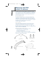
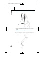
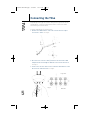
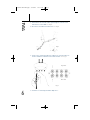
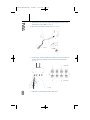
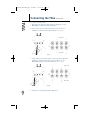
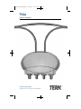
T4-0048-TV44-OM.qxp
4/28/04
11:31 AM
Page 2
TV44
Owner’s Manual
Amplified/Outdoor
Satellite Dish Clip-on Antenna
T4-0048-TV44-OM.qxp
4/28/04
11:31 AM
Page 1
Safety Precautions
Warning!
Use extreme caution when installing or removing an outdoor
antenna that is located close to overhead wires such as power lines,
telephone lines or cable TV lines. If any part of the antenna makes
contact with overhead power lines, touching the antenna or the
antenna cable can cause electrocution and death. If the antenna is
in contact with any type of overhead wires, call your power company
and ask them to send a qualified technician to remove the antenna.
Do not attempt to remove it yourself!
Important Safety Precautions...
Many do-it-yourself and professional antenna installers are injured
or killed each year by electric shock. While anyone can see the
obvious danger of falling, the most resourceful sometimes fail to
recognize overhead wires as being potentially lethal. To touch any
part of the antenna to these overhead wires is the same as touching
the wires with your bare hand. A very serious shock is almost sure
to result when contacting an electrical wire, and in the case of
primary wires on the tip of poles, the shock is like being struck by a
bolt of lightning. Many power wires are within 20 to 25 feet of the
ground and can easily be touched by an assembled antenna.
Please read and follow these important safety precautions:
• Get help from a qualified professional when removing the old
antenna if there is any doubt of clearing overhead wires.
• Never install the antenna outdoors at night or in inclement
weather conditions.
• Make sure the antenna downlead cable is connected to suitable
lightning arrestors.
• Make sure the antenna installation is secure.
Lightning protection
Always plug your TV and other electronic devices into a quality surge
protector for maximum protection against lightning and power surges.
• Be sure to select an antenna site well away from
all overhead wires.
• Do not try to guess which overhead wires carry high voltage.
Check with the power company.
• If you notice anything making contact with the overhead wires, call
the power company to have it removed safely.
• Do not run the downlead cable over power lines.
1
All outdoor antenna installations should be properly grounded. To
effectively protect the installations, the coaxial cable(s) should be
grounded before they enter the house. The grounding of the coaxial
cable is made using a “ground block” and copper wire (not
supplied). For information, and the materials needed to ground
your antenna installation, visit your local electronics store.
T4-0048-TV44-OM.qxp
4/28/04
11:31 AM
Page 2
About your new TV44
outdoor TV antenna
The TV44 features an internal amplifier that minimizes signal
loss. The satellite receiver powers the amplifier, so no additional
power supply is required. Because TERK’s antenna elements are
manufactured to be weather-resistant, they’ll perform at their
best for many years to come.
For best reception results...
For the best reception results, the satellite dish and antenna
combination should be high off the ground with minimal signal
obstructions. On the side of your house (close to the roof), or on
the roof itself, generally offers the best environment for reception.
Remember, you can always rotate the antenna on
the dish to adjust your reception.
Before you begin
Please take a moment to familiarize yourself with the various
elements in the TV44 package. Please make sure that your
package includes all of the necessary pieces (see Fig 1). If you
believe your box is missing any pieces, please call TERK Technical
Support at 1(800) 942-TERK (8325).
How to install your new TV44 antenna
The TV44 installation consists of three basic steps:
1. Install and connect the TV44 antenna
2. Install the indoor diplexers
3. Set up your television set(s) to use the TV44
Please be sure to complete all of these steps before attempting to
watch local channels with your TV44.
(1) TV44 Antenna
Fig 1
2
(4) Indoor Diplexers
(2) Security Clips
(4) 32” Coaxial Cables
(8) 12” Coaxial Cables
T4-0048-TV44-OM.qxp
4/28/04
11:31 AM
Page 3
Installing the TV44 on
a satellite dish
1. Make sure all satellite receivers are turned off and unplugged
from the electrical outlet.
2. Unsnap the antenna from the back notch of the mounting
clamp. See Fig 2.
Fig 2
3. Hold the antenna to the back of the dish so that the circular
housing is centered with the TERK logo facing out. See Fig 3.
Fig 3
3
T4-0048-TV44-OM.qxp
4/28/04
11:31 AM
Page 4
4. Maneuver the clamps over or around the edge of the dish one
at a time. See Fig 4.
Fig 4
5. Snap the antenna back into the back notch of the mounting
clamp.
6. Tighten the clamps by turning the thumb-wheel screw
clockwise.
Note: We recommend the use of the enclosed security clips for
any dish 20” or larger. Snap the security clips onto the TV44 and
slide down towards the mounting clips. See Fig 5.
Fig 5
4
T4-0048-TV44-OM.qxp
4/28/04
11:31 AM
Page 5
Connecting the TV44
Depending on the type of satellite dish you have, go to one of the
following five scenarios to determine how to connect the TV44
antenna to your satellite dish.
A-Single LNB (Phase1) Satellite Dish
1. Remove the LNB from the arm of the satellite dish to expose
the satellite cables. See Fig 6.
Fig 6.
2. Disconnect the satellite cable(s) from the satellite dish’s LNB
and pull them out through the bottom of the satellite dish arm.
See Fig 6.
3. Connect the satellite cables to the terminals marked OUT 1 and
OUT 2 on the TV44 antenna. See Fig 7.
Logo Side
Fig 7.
5
Dish Side
T4-0048-TV44-OM.qxp
4/28/04
11:31 AM
Page 6
4. Slide 2 black 32”antenna cables up through the satellite arm
and connect to the LNB. See Fig 8.
5. Reconnect the LNB to the dish arm. See Fig 8.
Fig 8.
6. Connect the remaining end of the 2 black 32” antenna cables to
the IN 1 and IN 2 terminals on the TV44 antenna. See Fig 9.
Logo Side
Dish Side
Fig 9.
6
7. Continue to “Installing the Indoor Diplexers.”
T4-0048-TV44-OM.qxp
4/28/04
11:31 AM
Page 7
Connecting the TV44 (continued)
B - Triple LNB (Phase3) Satellite Dish
1. Remove the LNB from the arm of the satellite dish to expose
the satellite cables. See Fig 10.
Fig 10.
2. Disconnect the satellite cable(s) from the satellite dish’s LNB
and pull them out through the bottom of the satellite dish arm.
See Fig 10.
3. Connect the satellite cables to the terminals marked
OUT 1, OUT 2, OUT 3, and OUT 4 on the TV44 antenna. See Fig 11.
Logo Side
Dish Side
7
Fig 11.
T4-0048-TV44-OM.qxp
4/28/04
11:31 AM
Page 8
4. Slide 4 black 32” antenna cables up through the satellite arm
and connect to the LNB. See Fig 12.
5. Reconnect the LNB to the dish arm. See Fig 12.
Fig 12.
6. Connect the remaining end of the 4 black 32” antenna cables to
the IN 1, IN 2, IN 3 and IN 4 terminals on the TV44 antenna.
See Fig 13.
Logo Side
Dish Side
Fig 13.
8
7. Continue to “Installing the Indoor Diplexers.”
T4-0048-TV44-OM.qxp
4/28/04
11:31 AM
Page 9
Connecting the TV44 (continued)
C - Phase 2 Satellite Dish
1. Disconnect the satellite cables from the “OUTPUT” or “TO
RECEIVER” terminals on your multiswitch.
2. Connect the satellite cables to the OUT 1, OUT 2, OUT 3,
and OUT 4 terminals on the TV44 antenna. See Fig 14.
Logo Side
Dish Side
Fig 14.
3. Using 4 black 32” antenna cables, connect the IN 1, IN 2, IN 3,
and IN 4, terminals of the TV44 to the “OUTPUT” or “TO
RECEIVER” terminals on your multiswitch. See Fig 15.
Logo Side
Dish Side
Fig 15.
9
4. Continue to “Installing the Indoor Diplexers.”
T4-0048-TV44-OM.qxp
4/28/04
11:31 AM
Page 10
D- Using a Multiswitch with an Antenna Input
1. Complete “Scenario A” instructions. (Page 5)
2. Locate your multiswitch and disconnect the satellite wire from
the 18 volt or Satellite A/101 18 volt terminal.
3. Connect the satellite wire to the TV/SAT terminal of the diplexer.
See Fig 16.
Fig 16.
Diplexer
Logo Side
Dish Side
4. Use one of the supplied white 12” antenna cables to connect
the “TV terminal” of the diplexer to the ANTENNA INPUT on
the multiswitch. See Fig 16.
10
5. Use the other supplied white 12” antenna cable to connect the
“SAT terminal” of the diplexer to the 18 volt (or Satellite “B”
Terminal) of the multiswitch. See Fig 16.
6. Continue to “Installing the Indoor Diplexers.”
T4-0048-TV44-OM.qxp
4/28/04
11:31 AM
Page 11
Connecting the TV44 (continued)
E - With Dish 500 Using SW21 Switches
1. Locate your SW21 multiswitches and disconnect the satellite
leads connected to the “TO RECIEVER” terminals. See Fig 17.
2. Connect the satellite leads to the OUT 1 and OUT 2 terminals
on the TV44. See Fig 17.
NOTE: You may need to extend the satellite leads using a barrel
connector and extra RG6 coaxial cable if they are not long enough.
3. Using 2 black 32” antenna cables connect the “TO RECIEVER”
terminals on the SW21 multiswitches to the IN 1 and IN 2
terminals on the TV44 antenna. See Fig 18.
Logo Side
Fig 17.
Dish Side
Fig 18.
Logo Side
Dish Side
Diplexer
Diplexer
11
NOTE: You may need to purchase longer antenna ca b les separa tely
if the supplied black 32” antenna cables are not long enough.
4. Continue to “Installing the Indoor Diplexers.”
T4-0048-TV44-OM.qxp
4/28/04
11:31 AM
Page 12
Installing the indoor diplexers
1. Disconnect the satellite cable from the “SAT IN” terminal on
your satellite receiver. See Fig 19 .
Fig 19.
2. Connect the satellite cable to the terminal marked “TV/SAT” on
the indoor diplexer. See Fig 20 .
3. Connect one of the supplied white 12” connector cables from
the terminal labeled “SAT” on the inside diplexer to your
satellite receiver’s “SAT IN” terminal. See Fig 20.
4. Connect the other white 12” connector cable from the terminal
labeled “TV” on the inside diplexer to your satellite receiver’s
“ANT IN” terminal. See Fig 20.
5. Connect a coaxial cable (not supplied) from the satellite
receiver’s “TV OUT” terminal to your te levision or VCR. See Fig 20.
6. Repeat step for each satellite receiver.
7. Continue to “Setting up your TV”.
Diplexer
Fig 20.
12
T4-0048-TV44-OM.qxp
4/28/04
11:31 AM
Page 13
Setting up your TV
1. Access the menu of your TV and make sure the TV is in ANT/AIR
mode and not CABLE/CATV mode. Please refer to your TV
manual for the exact steps to change this option.
2. Access the menu of your TV and run the “Auto Program” option.
Please refer to your TV manual for the exact steps to change
this option.
3. Set your TV to your favorite channel.
4. To fine tune local channel reception, rotate the TV44 antenna
around the perimeter of the dish until you receive the best
possible picture. Tighten the clips so that the antenna is firmly
secured to the satellite dish in that position.
5. The TV44 is now ready to receive local programming.
N o te: Sate l l i te re ce i ver should be turned off to view lo cal channels.
Limited Warranty
TERK TECHNOLOGIES CORP. (TERK) warrants this product
against defects in materials or workmanship for one year
from the date of purchase. During this warranty period this
product will be repaired or replaced, at TERK’s option,
without charge.
Please read your instructions thoroughly and use this
product only as directed. This warranty does not cover any
damage due to commercial use, accident, misuse, abuse,
or negligence. This warranty is valid only in the United
States of America.
Repair or replacement as provided under this warranty is
the exclusive remedy of the consumer. TERK shall not be
liable for any incidental or consequential damages for
breach of any expressed or implied warranty on this
product, except to the extent prohibited by applicable law.
Any implied warranty of merchantability or fitness for a
particular purpose on this product is limited to the duration
of this warranty.
For more information, visit www.terk.com. or,
for technical support, call 1.800.942.TERK (8375).
78P008A
TERK is a registered trademark. The TERK logo is a trademark of the TERK Technologies Corp.