1
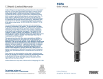
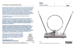
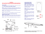
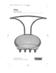
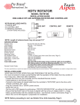
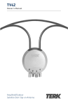
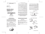
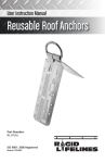
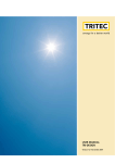
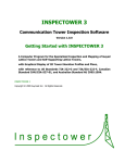
T0437-TV38 Revise-OM.qxp
11/11/03
04:34 AM
Page 1
TV38 HDTV ANTENNA PRO
Limited Warranty
Owner’s Manual
TERK Technologies Corp. (TERK) warrants this product against
defects in materials or workmanship for one (1) year from the date of
purchase. During this warranty period, this product will be replaced
without charge. This warranty does not cover any damage due to acts
of nature, commercial use, accident, misuse, abuse or negligence.
This warranty is only valid in the USA. Replacement as provided
under this warranty is the exclusive remedy of the consumer. TERK
shall not be liable for any incidental or consequential damages for
breach of any express or implied warranty on this product, except to
the extent that limitations of this sort are prohibited by applicable
law. THERE ARE NO IMPLIED WARRANTIES OF MERCHANTABILITY
OR FITNESS FOR A PARTICULAR PURCHASE EXCEPT TO THE EXTENT
THAT IMPLIED WARRANTIES OF EITHER SORT ARE REQUIRED BY
APPLICABLE LAW, AND IN SUCH CASE, EACH WARRANTY IS LIMITED
IN DURATION TO ONE YEAR.
Performance Specifications
Type:
Active Elements:
Antenna Selector:
Dimensions:
Height:
Width:
Length:
Turning Radius:
HDTV/UHF/VHF/FM
43
Pink
311/2"
111"
1493/4"
90”
TERK and TERK Technologies are trademarks of TERK Technologies Corp.
Commack, NY ©2003 TERK Technologies Corp. Made in USA.
For additional information: call 1.800.942.TERK (8375) or visit
www.terk.com.
113P006A
1450191
TERK is a registered trademark. The TERK logo is a trademark of the TERK Technologies Corp.
Large Directional
UHF/VHF/FM Antenna
T0437-TV38 Revise-OM.qxp
11/11/03
04:34 AM
Page 1
Safety Precautions
TV38
TV38
WARNING
READ ALL OF THE ATTACHED SAFETY INSTRUCTIONS BEFORE
PROCEEDING WITH ANTENNA AND/OR MAST ASSEMBLY AND
INSTALLATION. INSTALLATION OF THIS ANTENNA NEAR
POWER LINES IS DANGEROUS. FOR YOUR SAFETY, FOLLOW THE
INSTALLATION INSTRUCTIONS.
Safety Precautions (continued)
Use extreme caution when installing or removing an outdoor
antenna that is located close to overhead wires such as power
lines, telephone lines or cable TV lines. If any part of the antenna
makes contact with overhead power lines, touching the antenna
or the antenna cable can cause electrocution and death. If the
antenna is in contact with any type of overhead wires, call your
power company and ask them to send a qualified technician to
remove the antenna. Do not attempt to remove it yourself.
Important Safety Precautions:
Many do-it-yourself and professional antenna installers are
injured or killed each year by electric shock. While anyone can
see the obvious danger of falling, the most resourceful
sometimes fail to recognize overhead wires as being potentially
lethal. To touch any part of the antenna to these overhead wires
is the same as touching the wires with your bare hand. A very
serious shock is almost sure to result when contacting an
electrical wire, and in the case of primary wires on the top of
poles, the shock is like being struck by a bolt of lightning. Many
power wires are within 20 to 25 feet of the ground and could
easily be touched by an assembled antenna.
If you are not completely sure that you can install the antenna
safely, Do Not Try It! Contact a professional installer instead.
Follow These Rules and Live:
1. Perform as much antenna assembly on the ground
as possible.
2. Watch out for overhead power lines and be sure to select an
antenna site well away from all overhead wires. Check the
distance to the power lines before you start installing. It is
recommended that you stay a minimum of twice the length
of the antenna plus the length of the mast away from ALL
power lines.
3. Do not use a metal ladder.
4. Remember, even the slightest touch of the antenna to a
power line can cause a fatal shock. Do not try to guess
which overhead wires carry high voltage - check with the
power company.
5. Never install the antenna outdoors at night, when it is windy,
or during rain or snow.
6. Have a spotter when you are on the roof; they can see things
you may miss.
7. If you start to drop the antenna, let it go. You could lose your
balance and fall also.
8. If anything comes into contact with a power line - CALL YOUR
POWER COMPANY! DO NOT ATTEMPT TO REMOVE IT
YOURSELF! They will remove it for you.
9. Mast, downlead and guy wires are all excellent conductors.
Keep them away from power lines also. Do not run the
downlead cable over power wires.
10. Make sure the antenna installation is secure.
11. Do not stand on, lean on, hang from or hang anything on the
antenna once it is mounted.
12. Make sure the antenna mast assembly and downlead are
grounded per National Electrical Code.
(See page 14.)
Lightning Protection and Grounding:
• Always plug your TV and other electronic devices into a
quality surge protector (such as the TERK TSP-6), for
maximum protection against lightning and power surges.
• Do not run the downlead cable over power wires.
• Make sure the antenna downlead is connected to suitable
lightning arrestors.
1
2
T0437-TV38 Revise-OM.qxp
11/11/03
04:34 AM
Page 3
Antenna Assembly
Antenna Assembly (continued)
TV38
TV36
Boom Brace
Large Boom
1. Unfold the elements on the two reflector booms until they lock
into place. Make sure that they are straight and perpendicular to
the boom.
2. Attach the two reflector booms using the attached nut and bolt so
that they are perpendicular to the smaller boom. (See figure 1.)
Rear Boom
Front Boom
Fig. 1
Mast
Reflector Booms
3. Unfold the reflector booms until they lock into place.
(See figure 2.)
Fig. 2
4. Unfold all the other elements on the antenna until they lock
into place ensuring that they are flat and parallel to each other.
(See figure 3.)
Fig. 3
3
4
T0437-TV38 Revise-OM.qxp
11/11/03
04:34 AM
Page 5
Antenna Assembly (continued)
TV38
TV38
5. Find the larger antenna section and remove the nut and
bolt. Slide the narrow boom of the front antenna into the
larger section. Tap lightly with a rubber mallet on the end
of the small boom aligning the bolt holes. (See figure 4.)
Re-install the bolt and nut; be sure to tighten it securely.
Antenna Assembly (continued)
NOTE: Make sure that the side of the small boom with the phasing lines
line up with the nuts on the large boom.
7. Remove the rear nut and bolt from the larger antenna section.
Slide the narrow boom of the rear antenna into the larger
section. Tap lightly with a rubber mallet on the end of the
small boom, aligning the bolt holes. (See figure 6.)
Re-install the bolt and nut; be sure to tighten it securely.
8. Remove the nut and washer from the top of the last element
holder stud on the top side of the antenna and repeat the
process on the last element holder stud on the bottom side of
the antenna. (See figure 6.) Place the phasing lines from the rear
section over the stud, one on the top side, one on the bottom,
and reattach the washers and hex nuts. Tighten them securely.
Fig. 4
Fig. 6
6. Remove the nuts and washers from the top of the first element
holder studs. (See figure 5.) Place the phasing lines from the
front section over the studs, and re-attach the washers and
hex nuts. Tighten them securely.
9. Lay the boom brace on top of the antenna keeping all the
U-bolts on the same side. Locate the bolt hole in the corner
reflector and attach the brace with the bolt and nut. Swing the
boom brace down towards the rear. Form a "V" with the metal
straps. Bolt the “V” to each side of boom. (See figures 7 and 8.)
Phasing Lines
Fig. 5
Fig. 7
5
6
Fig. 8
T0437-TV38 Revise-OM.qxp
11/11/03
04:35 AM
Page 7
Antenna Assembly (continued)
Antenna Assembly (continued)
TV38
TV38
10. Loosen the nuts on the downlead connections. Attach the transformer
ends to the studs, between the washers, and tighten the nuts securely.
(See figure 9.) Attach the coax downlead to the transformer.
Fig. 9
11. Loosen the U-bolt nuts, slide the TV38 antenna over the mast and
lightly tighten the two mast clamps. (See figure 10, 11.) The top side of
the antenna is the side with the black plastic pieces on it.
NOTE: The top side of the antenna is the side with the black plastic pieces
on top of the large boom.
Fig. 10
Fig. 11
12. Connect the coax downlead to your TV. Rotate the TV38 antenna
until you receive the best picture. You will probably need a helper to
view the TV set while you are rotating the antenna. See “Pointing
the Antenna Towards the Broadcast Tower”
Downlead
Connections
Transformer
Point this end
towards the
broadcast tower
NOTE: Point the small end of the antenna towards the station
broadcast tower.
13. Tighten the two mast clamps securely.
14. Secure the coaxial downlead to the mast (using cable ties) to prevent
it from whipping by the wind.
15. Ground the antenna and mast per the accompanying grounding
instructions. (See page 14.)
7
8
Pointing the Antenna Towards the Broadcast Tower
1. Go to www.terk.com and click on the “Antenna Locator.”
2. Enter your home address and then “Submit.”
3. Click “View Street Level Map” to see in which direction you
should face your antenna.
T0437-TV38 Revise-OM.qxp
11/11/03
04:35 AM
Page 9
General Installation Instructions
for Mast Mounted Antennas
TV38
TV38
1. Assemble your antenna on the ground at the installation site
per the instructions.
2. On the ground, attach the antenna to the mast. Pull enough
coax downlead and connect to the antenna per its instructions.
3. To insure that the mast does not fall, a durable nonconductive
rope should be attached to each ten foot section as it is raised.
4. Install the selected mounting bracket.
5. If you are using guy wire installation (not included) instead of
a mounting bracket:
• Install guy anchor bolts.
• Estimate length of guy wire and cut.
• Attach to mast using a guy ring.
6. Carefully take the antenna and mast assembly to the mounting
bracket and insert. Tighten the clamp bolts. In case of a guyed
installation, it will be necessary to have at least a second
person hold the mast upright while the guy wires are attached
and tightened to the anchor bolts.
Where To Install Your Antenna
Before attempting to install your antenna, decide on the
best location to install your antenna for both safety and
performance. To determine a safe distance from wires, power
lines and trees:
1. Measure the length of your antenna and multiply by 2.
2. Add this measurement to the length of your tower/mast.
If you are unable to maintain this safe distance, STOP! Get
professional help. Most antennas are supported by tripod
masts or pipe masts attached to the chimney, roof, or to the
side of the house. Generally, the higher the antenna, the better
it performs. Good practice is to install your antenna about 5
to10 feet above the roof line and away from power lines and
other obstructions.
NOTES:
• Remember when doing any installation, keep the
mast plumb.
Antenna Removal
Removal of the antenna should be exactly the reverse of the
installation instructions. Please, for your own safety, follow
the instructions for installing the antenna starting with the last
step first.
• For mast support, use only 1-1/4” O.D. pipe or larger antenna
mast sections. Lengths over 10 feet should be guyed at least
every 10 foot section.
• Not all mounting methods are shown here. Read and follow
the mount manufacturer’s instructions carefully.
House Construction Obstacles:
For homes made of stucco, clad with aluminum siding or that have
internal foil paper insulation, the antenna must be installed on the
side of the house that faces the broadcasting tower. These
materials may prevent signals from going through it.
9
10
T0437-TV38 Revise-OM.qxp
11/11/03
04:35 AM
Page 11
Types of Support Structures
and Mounting
Fig. 12
TV38
TV38
Chimney Mount - Mounts on a chimney only
Types of Support Structures
and Mounting (continued)
Suggested height limitation: 10 feet above chimney top.
The chimney is often an easy and convenient mounting place,
but the chimney must be strong enough to support the
antenna in high winds. Do not use a chimney that has loose
bricks or mortar. A good chimney mount consists of a 5 or 10
foot 1-1/4” diameter steel mast and two heavy duty strap
clamp-type brackets.
Attic
An attic installation is the easiest, fastest and most convenient
type of antenna installation, especially if you do not have easy or
secure access to an outdoor area. Attic installations work best in
areas where strong signals are present. Roofing materials,
aluminum foil on insulation, aluminum or steel siding, metal
gutters at the attic level, and metal lath under old plaster walls
all can interfere with reception. Use the universal mount to
secure the mast and antenna to a rafter.
1. Insert the threaded end of the strap hook, (the one secured to
the strap) through the end portion of the “Z” mount (hole A).
Take one of the loose strap hooks and insert into hole B.
NOTE: It is important to thread the nut only 1/4” onto the hook, so
that it may later be tightened to take out the slack and make the
strap secure to the chimney.
1. Screw the universal mount into a supported rafter or beam.
2. Using the U-bolt, bracket and nuts, secure the mast to the
universal mount.
3. After you align the mast perpendicular to the floor, tighten
the nuts securely.
2. Go around the chimney with the strap; slip the strap clip onto
the strap, and then secure the other end of the strap by inserting
the strap into the strap hook that is in hole B. The strap clip is
used as follows: (See figure 12.)
a. Slide the strap through the loop section of the clip and bend it
around through the upright section of clip.
b. Bend the upright sections of the clip down with pliers,
pinching the strap firmly.
3. At this time, remove any slack in the strap by tightening the nuts
at holes A and B.
4. Repeat the above steps to secure the lower mount to chimney.
(It is recommended that the mounts be a minimum of 18” apart.)
11
NOTE: Install the upper bracket just below the top course of
bricks, and the lower bracket two or three feet below the upper
bracket. For maximum strength, space the brackets as far apart
as possible.
5. Place the mast against the mount and secure it in place using
the mast support clamps and nuts.
Universal Mount - For attic installations
12
T0437-TV38 Revise-OM.qxp
11/11/03
04:35 AM
Page 13
Types of Support Structures
and Mounting (continued)
TV38
TV38
Wall Mount
Example of Antenna
Grounding
NOTE: Grounding the antenna and mast provides lightning protection for
the antenna and your TV set.
All outdoor antenna installations should be properly grounded. To
effectively protect the installation, the coaxial cable(s) should be grounded
before they enter the house. The grounding of the coaxial cable is made
using a “ground block” and copper wire (not supplied). For information and
the materials needed to ground your antenna installation, visit your local
electronics store.
If you are not sure how to install the grounding block and rod, please
consult your local retailer or TERK’S Technical Support Department at
1-800-942-8375.
Suggested height limitation: 10 feet above the rooftop.
An outside wall of your home is also an easy and convenient
mounting place, but the wall and fasteners that you use must be
strong enough to support the antenna in high winds. Ensure that
the brackets are securely fastened to a solid part of your wall.
Example of antenna grounding as per
National Electrical Code, ANSI/NFPA 70
1. Space the mounting brackets on an exterior wall – be sure
to clear roof eaves or any other obstacles.
2. Secure the brackets to the wall using the 4 lag screws.
3. Insert the mast between the saddles and secure with the
nuts and bolts.
Grounding Wire Conductors
(NEC Section 810-21)
Electric
Service
Equipment
Tripod Mount (not included) - Used on peaked and flat roofs
Suggested height limitation: 10 feet above the rooftop.
Installation involving a tripod mount and a mast should be guyed if
the mast is ten feet or more. The tripod mount must be securely
anchored to the roof as should the guy wires. Apply roofing
compound around the base of the brackets, screws and eyebolts to
weather proof the holes in the roof. Try to lag bolt the legs to the
roof rafters. If not, install wood plates in the attic and install bolts
to secure the mount.
Power Service Grounding
Electrode System
(NEC Art 250, Part H)
Antenna
Discharge Unit
(NEC Section 810-20)
Ground
Clamps
Rain Drip Loop On
Lead-in To TV
NEC - National Electrical Code
1. Mount the 75 ohm grounding block or discharge unit as close as possible
to where the downlead enters the house.
2. The ground wires for both the mast and the downlead should be copper
or aluminum wire, number eight (8) or larger.
3. The downlead wire from the antenna to the antenna grounding block or
discharge unit and the mast ground wire should be secured to the house
with stand-off insulators, spaced from four (4) to six (6) feet apart.
Telescopic Mast (not included)
The minimum safe diameter of the mast is 1-1/4 inches for this
type of mount. Guy wires should be equally spaced in at least three
directions. Use at least three guy wires for each ten foot section
of mast. Make sure guy wires are spaced evenly apart.
13
Antenna Lead
in Wire
Ground
Clamp
NOTE: In the case of a “ground up” antenna installation, it may not be
necessary to ground the mast if the mast extends four or more feet into the
ground. Consult a TV serviceman for the proper depth in your location.
14