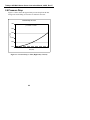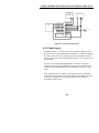
1
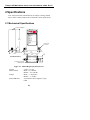
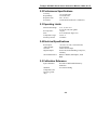
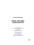
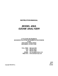
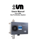
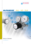
MODEL 452
PROCESS OZONE SENSOR
©Teledyne Instruments
Advanced Pollution Instrumentation Division
(T-API)
9480 Carroll Park Drive
San Diego, CA 92121-5201
TOLL-FREE:
TEL:
FAX:
E-MAIL:
WEB SITE:
800-324-5190
858-657-9800
858-657-9816
[email protected]
www.teledyne-api.com
Teledyne API M452 Ozone Sensor Instruction Manual, 02852, Rev. E
SAFETY MESSAGES
NOTE
The M452 contains no user serviceable parts.
CAUTION
There is risk of dangerous UV exposure when the
cover is removed from the sensor. Take necessary
precautions to avoid exposure.
CAUTION
High voltages exist inside the sensor. Please use
caution when sensor cover is removed.
i
Teledyne API M452 Ozone Sensor Instruction Manual, 02852, Rev. E
TABLE OF CONTENTS
SAFETY MESSAGES............................................................................ I
TABLE OF CONTENTS .................................................................... III
LIST OF FIGURES ...............................................................................V
LIST OF TABLES .................................................................................V
WARRANTY POLICY......................................................................VII
1 PRODUCT DESCRIPTIONS......................................................... 1-1
1.1 M452 PROCESS OZONE SENSOR .................................................. 1-1
1.2 M452 HIGH PURITY PROCESS OZONE SENSOR............................. 1-1
2 SPECIFICATIONS ......................................................................... 2-1
2.1 MECHANICAL SPECIFICATIONS .................................................... 2-1
2.2 PERFORMANCE SPECIFICATIONS .................................................. 2-2
2.3 OPERATING LIMITS ...................................................................... 2-2
2.4 ELECTRICAL SPECIFICATIONS ...................................................... 2-2
2.5 CALIBRATION REFERENCE ........................................................... 2-2
2.6 PRESSURE DROP........................................................................... 2-3
2.7 OPTIONS....................................................................................... 2-4
2.7.1 AC Power Adapter ............................................................... 2-4
2.7.2 Ozone Destructor (1/4” Tube Fittings)................................ 2-4
3 THEORY OF OPERATION .......................................................... 3-1
4 INSTALLATION............................................................................. 4-1
4.1 UNPACKING ................................................................................. 4-1
4.2 MECHANICAL INSTALLATION....................................................... 4-1
4.3 ELECTRICAL CONNECTIONS ......................................................... 4-1
4.3.1 Power Supply ....................................................................... 4-2
4.3.2 Analog Output...................................................................... 4-3
4.3.3 Zero Calibration Input......................................................... 4-3
4.3.4 Status Outputs ...................................................................... 4-4
4.3.5 RS232/485 Interface ............................................................ 4-5
4.4 GAS CONNECTIONS ...................................................................... 4-6
4.5 START-UP AND CALIBRATION PROCEDURE.................................. 4-7
iii
Teledyne API M452 Ozone Sensor Instruction Manual, 02852, Rev. E
5 SENSOR AND SYSTEM TROUBLESHOOTING ...................... 5-1
5.1 STATUS LED’S ............................................................................. 5-1
5.2 STATUS OUTPUTS ......................................................................... 5-2
5.3 SENSOR O.K................................................................................. 5-2
5.4 INVALID READING ........................................................................ 5-3
5.5 LAMP LOW ................................................................................... 5-3
5.6 CELL DIRTY ................................................................................. 5-4
5.7 STATUS OUTPUT SUMMARY TABLE ............................................. 5-4
iv
Teledyne API M452 Ozone Sensor Instruction Manual, 02852, Rev. E
LIST OF FIGURES
FIGURE 2-1:
FIGURE 2-2:
FIGURE 4-1:
FIGURE 4-2:
M452A HIGH PURITY OZONE SENSOR .............................. 2-1
PRESSURE DROP VS. FLOW (HIGH PURITY VERSION)........ 2-3
ELECTRICAL CONNECTIONS .............................................. 4-2
DIGITAL OUTPUT CONNECTIONS ....................................... 4-4
LIST OF TABLES
TABLE 5-1: STATUS OUTPUTS ............................................................... 5-2
TABLE 5-2: STATUS OUTPUT TRUTH TABLE ......................................... 5-4
v
Teledyne API M452 Ozone Sensor Instruction Manual, 02852, Rev. E
WARRANTY POLICY
ADVANCED POLLUTION INSTRUMENTATION DIVISION
02024c
Prior to shipment, Teledyne API equipment is thoroughly inspected and
tested. Should equipment failure occur, Teledyne API assures its
customers that prompt service and support will be available.
COVERAGE
After the warranty period and throughout the equipment lifetime, Teledyne
API stands ready to provide on-site or in-plant service at reasonable rates
similar to those of other manufacturers in the industry. All maintenance
and the first level of field troubleshooting are to be performed by the
customer.
NON-API MANUFACTURED EQUIPMENT
Equipment provided but not manufactured by Teledyne API is warranted
and will be repaired to the extent and according to the current terms and
conditions of the respective equipment manufacturers warranty.
GENERAL
Teledyne API warrants each Product manufactured by Teledyne API to be
free from defects in material and workmanship under normal use and
service for a period of one year from the date of delivery. All replacement
parts and repairs are warranted for 90 days after the purchase.
If a Product fails to conform to its specifications within the warranty
period, Teledyne API shall correct such defect by, in Teledyne API's
discretion, repairing or replacing such defective Product or refunding the
purchase price of such Product.
The warranties set forth in this section shall be of no force or effect with
respect to any Product: (i) that has been altered or subjected to misuse,
negligence or accident, or (ii) that has been used in any manner other than
in accordance with the instruction provided by Teledyne API or (iii) not
properly maintained.
vii
Teledyne API M452 Ozone Sensor Instruction Manual, 02852, Rev. E
THE WARRANTIES SET FORTH IN THIS SECTION AND THE
REMEDIES THEREFORE ARE EXCLUSIVE AND IN LIEU OF ANY
IMPLIED WARRANTIES OF MERCHANTABILITY, FITNESS FOR
PARTICULAR PURPOSE OR OTHER WARRANTY OF QUALITY,
WHETHER EXPRESSED OR IMPLIED. THE REMEDIES SET
FORTH IN THIS SECTION ARE THE EXCLUSIVE REMEDIES FOR
BREACH OF ANY WARRANTY CONTAINED HEREIN. TELEDYNE
API SHALL NOT BE LIABLE FOR ANY INCIDENTAL OR
CONSEQUENTIAL DAMAGES ARISING OUT OF OR RELATED TO
THIS AGREEMENT OF TELEDYNE API'S PERFORMANCE
HEREUNDER, WHETHER FOR BREACH OF WARRANTY OR
OTHERWISE.
TERMS AND CONDITIONS
All units or components returned to Teledyne API should be properly
packed for handling and returned freight prepaid to the nearest designated
Service Center. After the repair, the equipment will be returned, freight
prepaid.
viii
Teledyne API M452 Ozone Sensor Instruction Manual, 02852, Rev. E
1 Product Descriptions
1.1 M452 Process Ozone Sensor
The Teledyne API M452 is a microprocessor-based sensor for measuring
the concentration of gaseous ozone in processes such as semiconductor
wafer fabrication, water treatment, and ozone research. The M452 can be
used as a full flow process sensor or as a sensor to monitor a small flow of
gas diverted from a process stream.
The M452 features a standard 0-5 volt analog signal for reporting process
concentration as well as 4 digital status outputs for sensor diagnostics. A
bi-directional serial interface is also provided for computer control.
The M452 operates from an external +15 vdc power source.
1.2 M452 High Purity Process Ozone Sensor
The M452A High Purity Process Ozone Sensor includes a 316L manifold
with a 10Ra finish. ¼” VCR™ face seal fittings are standard.
1-1
Teledyne API M452 Ozone Sensor Instruction Manual, 02852, Rev. E
INTENTIONALLY BLANK
1-2
Teledyne API M452 Ozone Sensor Instruction Manual, 02852, Rev. E
2 Specifications
Note: All specifications contained herein are subject to change without
notice. Please contact Teledyne API to obtain the current specifications.
2.1 Mechanical Specifications
15 PIN "D" CONNECTOR
Model 452A
Electrical connections;
1 Analog out −
2 Analog out +
3 Ground
4 +15V in
5 +15V in
6 Digital in #1
7 Digital in #2
8 Digital out #1
9 Digital out #2
10 Digital out #3
11 Digital out #4
12 Digital out common (emitters)
13 RS485−A
14 RS485−B
15 Ground
6.71
[170.4]
Female 1/4" VCR
Gland and Nut
.50
[12.7]
1.06
[27.0]
2.13
[54.0]
.99
[25.1]
Male 1/4" VCR
Gland and Nut
5.13
[130.3]
.26
[6.6]
.49
[12.4]
3.15
[80.0]
.51
[13/1]
X.XX = Dimensions in inches
[XX.X] = Dimensions in millimeters
4X 8-32UNC-2B X .125 [3.2] DP
MOUNTING HOLES
1.10
[27.9]
Figure 2-1: M452A High Purity Ozone Sensor
Weight:
Surface Finish:
Fittings:
Wetted Materials:
2.8 lbs. (1.27 kg)
M452 - 32 µ inch Ra
M452A – 10 µ inch Ra
M452 – ¼” Gyrolok™
M452A – ¼” VCR™
316L Stainless Steel, Sapphire, Virgin
PTFE
2-1
Teledyne API M452 Ozone Sensor Instruction Manual, 02852, Rev. E
2.2 Performance Specifications
Accuracy:
Repeatability:
Response Time:
Zero Drift:
±1% of Full Scale.
1% of Full Scale
2 sec. To 95%
1% Full Scale/month (non –cumulative)
2.3 Operating Limits
Measurement Range:
Proof pressure:
Flow:
Temperature range:
Warm-Up Period:
5, 10, 15, 20% w/w
25, 50, 100, 200, 400 g/Nm3
115 psia
0.1-5.0 LPM (See Figure 2-2)
5 to 45 °C
15 minutes
2.4 Electrical Specifications
Power Input:
Analog Output:
Zero Cal:
Digital Outputs:
Serial Data Interface:
+15 volts ±1.0 volt (1.0A maximum)
0-5V Full Scale
Contact Closure Input
Sensor OK, Invalid Reading, Lamp Low,
Cell Dirty
RS232 or RS485, Half-Duplex, 9600
Baud
2.5 Calibration Reference
Span Calibration:
Standard
Temperature and
Pressure (g/Nm3
only):
Traceable to Buffered KI laboratory
calibration
0°C and 760 mmHg
2-2
Teledyne API M452 Ozone Sensor Instruction Manual, 02852, Rev. E
2.6 Pressure Drop
Figure 2-2 below shows the approximate pressure drop from the inlet
fitting to the outlet fitting as a function of volumetric flow rate.
Pressure Drop vs. Flow
1.000
y = 0.0008x2 + 0.0048x
∆P (psi)
0.800
0.600
0.400
0.200
0.000
0
5
10
15
20
Flow (LPM)
Figure 2-2: Pressure Drop vs. Flow (High Purity Version)
2-3
25
Teledyne API M452 Ozone Sensor Instruction Manual, 02852, Rev. E
2.7 Options
The M452 is available with the following options:
2.7.1 AC Power Adapter
This option consists of a Universal Input (100-240 VAC, 50-60Hz) Power
Adapter with a standard IEC320 modular AC receptacle. A North
American standard 3 prong power cord is also provided.
2.7.2 Ozone Destructor (1/4” Tube Fittings)
This option consists of an external catalytic Ozone Destructor for
connecting to the gas outlet of the M452. The Ozone Destructor is
provided with ¼” compression tube fittings. When the Ozone Descructor
is used in conjunction with the M452, the gas flow rate must be limited to
a maximum of 1.0 L/min.
2-4
Teledyne API M452 Ozone Sensor Instruction Manual, 02852, Rev. E
3 Theory of Operation
The detection of ozone molecules is based on absorption of 254 nm UV
light due to an internal electronic resonance of the O3 molecule. The
Model 452 uses a mercury lamp constructed so that a large majority of the
light emitted is at the 254 nm wavelength. Light from the lamp shines
through an absorption cell through which the sample gas being measured is
passed. The ratio of the intensity of light passing through the gas to a
reference measurement, which does not pass through the gas, forms the
ratio I/Io. This ratio forms the basis for the calculation of the ozone
concentration.
The Beer-Lambert equation, shown below, calculates the concentration of
ozone from the ratio of light intensities.
C O3 = −
Ι
1
Τ
14.695 psi
×
× ln
×
o
Ρ
Ιo
α × l 273 Κ
Where:
I
= Intensity of light passed through the sample
= Intensity of light through sample free of ozone
Io
= Absorption coefficient
α
= Path length
l
= Concentration of ozone
CO
3
T
P
= Sample temperature in degrees Kelvin
= Pressure in pounds per square inch (absolute)
As can be seen the concentration of ozone depends on more than the
intensity ratio. Temperature and pressure influence the density of the
sample. The density changes the number of ozone molecules in the
absorption cell, which impacts the amount of light, removed from the light
beam. These effects are addressed by directly measuring temperature and
pressure and including their actual values in the calculation. The
absorption coefficient is a number that reflects the inherent ability of ozone
to absorb 254 nm light. Lastly, the absorption path length determines how
many molecules are present in the column of gas in the absorption cell.
3-1
Teledyne API M452 Ozone Sensor Instruction Manual, 02852, Rev. E
The intensity of light is converted into a voltage by the detector/preamp
module. The voltage is converted into a number by a voltage-to-frequency
(V/F) converter capable of 80,000 count resolution. The digitized signal,
along with the other variables, is used by the CPU to compute the
concentration of ozone using the above formula.
3-2
Teledyne API M452 Ozone Sensor Instruction Manual, 02852, Rev. E
4 Installation
4.1 Unpacking
Upon receiving the M452 please verify that no apparent shipping damage
has occurred. If damage has occurred please advise shipper first, then
Teledyne API.
4.2 Mechanical Installation
Mount the M452 to a stable platform using four #8-32UNC screws. See
Figure 2-1 for mounting hole dimensions.
NOTE
If the mounting platform is non-conductive or
note connected to earth ground, then a separate
connection to earth ground should be made using
one of the mounting screws. Failure to provide a
proper earth ground connection may make the
M452 susceptible to electrical interference from
external sources.
4.3 Electrical Connections
Electrical connections are made to the M452 using the 15 pin D-Sub
connector on the top of the device. Figure 4-1 shows the pin-out of the 15pin connector and typical connections.
4-1
Teledyne API M452 Ozone Sensor Instruction Manual, 02852, Rev. E
Ozone Concentration
Meter
(0-5 VDC)
or Data Acqusition Device
-
+
Power Supply
+15V
Common
Analog Out Digital Out #2
Status Display
or
PLC
Analog Out +
Digital Out #3
Power Common
Digital Out #4
+15 Volt Supply
Digital Out Common
+15 Volt Supply
RS485-A
Digital In #1
Zero Cal = Closed
RS485-B
Digital In #2
Power Common
Digital Out #1
Figure 4-1: Electrical Connections
4.3.1 Power Supply
The M452 requires a +15 VDC power source capable of supplying 1.0 A.
DC power can be connected through the male DB-15 connector or through
the coaxial power jack. The coaxial power jack is configured so that the
ground connection is on the outside (shield) and the +15V connection is on
the center pin.
If power is to be supplied through the DB-15 connector, the positive
terminal of the power supply should be connected to pins 4 and 5 on the
15-pin connector and the common terminal should be connected to pins 3
and 15.
If the optional AC Power Adapter is used to provide power, it should be
connected to the coaxial power connector adjacent to the DB-15 connector
on the top of the M452. Use only the approved AC Power Adapter
provided by Teledyne API.
4-2
Teledyne API M452 Ozone Sensor Instruction Manual, 02852, Rev. E
4.3.2 Analog Output
The analog output is a 0-5 volt signal representing the ozone concentration
measured by the sensor. The output is scaled to the concentration range
that the sensor has been set to measure. Check the serial number label on
the M452 to determine the concentration range.
For best performance, the analog output should be connected to a
voltmeter or A/D converter with a differential input and a minimum input
impedance of 2KΩ.
4.3.3 Zero Calibration Input
The zero calibration input is located on Digital Input #1. To zero the
M452, Digital Input #1 should be connected to the power common for at
least 1 second. This can be accomplished using a Normally Open switch or
relay.
4-3
Teledyne API M452 Ozone Sensor Instruction Manual, 02852, Rev. E
4.3.4 Status Outputs
The M452 has four digital status outputs for indicating error status and
when operational parameters have moved out of normal limits. These
outputs are in the form of opto-isolated open-collector transistors. They
can be used to drive status LED’s on a display panel or interface to a
digital device such as a Programmable Logic Controller (PLC).
Figure 4-2 below shows the most common way of connecting the digital
outputs to an external device such as PLC. Note: Most devices, such as
PLC’s, have internal provision for limiting the current that the input will
draw from an external device. When connecting to a unit that does not
have this feature, external dropping resistors must be used to limit the
current through the transistor output to 50mA or less.
See Section 1 for details on using the Status Outputs for diagnosing sensor
and system-level malfunctions.
M452
Programmable Logic
Controller or other device
+5V
Digital Output #1-4 (Collector)
Digital
Input
Digital Output Common (Emmiter)
Ground Provided
by PLC
Opto-Isolator
Figure 4-2: Digital Output Connections
4-4
Teledyne API M452 Ozone Sensor Instruction Manual, 02852, Rev. E
4.3.5 RS232/485 Interface
The M452 features a bi-directional digital serial interface that can be used
for sensor control and data acquisition. Please contact Teledyne API for
documentation on the use of the RS232/485 interface.
4-5
Teledyne API M452 Ozone Sensor Instruction Manual, 02852, Rev. E
4.4 Gas Connections
Gas connections to the M452 are made using ¼” compression tube fittings
(M452) or ¼” VCR™ face seal fittings (M452A.) The ¼” compression
fittings can be used with ¼” O.D. Stainless Steel or Teflon™ tubing. The
M452 is not sensitive to flow direction; it does not matter which of the two
fittings is used as the gas inlet.
To avoid contamination of the optical cell in the M452, ensure that all
tubing upstream of the M452 is properly cleaned and purged before the
M452 is installed.
In order to achieve an acceptable response time and to avoid sample
degradation, the system should be set up so that a minimum flow rate of
0.1 LPM is established through the M452. If long tubing runs are used
between the measurement point and the M452, then higher flow rates
should be used to avoid sample degredation. Appropriate tests should be
conducted to determine minimum flow requirements.
4-6
Teledyne API M452 Ozone Sensor Instruction Manual, 02852, Rev. E
4.5 Start-Up and Calibration Procedure
1.
Verify that the proper electrical connections have been made (See
Section 4.3) and apply power to the M452. Allow the M452 to warm
up for at least 15 minutes.
2.
Purge the M452 with zero gas (usually oxygen) at a minimum flow
rate of 0.1 LPM for at least 2 minutes.
3.
Check that the Status Outputs (See Section 4.3.4) are in their normal
states and no errors are indicated.
4.
Close the zero calibration input (See Section 4.3.3) for a minimum of
1 second to perform the automatic zero calibration.
5.
Re-check the Status Outputs to ensure that no errors are indicated.
6.
Check the voltage on the analog output (See Section 4.3.2) and verify
that it reads 0.000 ± 0.010 volts.
7.
The M452 is now ready for operation.
4-7
Teledyne API M452 Ozone Sensor Instruction Manual, 02852, Rev. E
5 Sensor and System
Troubleshooting
This chapter gives guidelines for diagnosing system and sensor
malfunctions using the four digital Status Outputs provided by the M452.
All troubleshooting should be done after the M452 has been turned on and
allowed to warm up for at least 15 minutes.
5.1 Status LED’s
On the top of the M452 are five status LED’s.
The Status LED labeled ‘CPU STATUS’ is used to verify the status of the
CPU inside the M452. This LED should blink on and off continuously
while the sensor is on. If this LED stops blinking while power is applied
to the sensor, a CPU failure is indicated.
The other four Status LED’s on the M452 exactly mirror the four Status
Outputs described in the following sections.
5-1
Teledyne API M452 Ozone Sensor Instruction Manual, 02852, Rev. E
5.2 Status Outputs
Table 5-1 below describes the function of the status outputs. More details
as to the meaning of the status outputs are described in the following
sections.
Table 5-1: Status Outputs
Output #
Name
On State
Off state
1
Sensor
O.K.
Normal State
Reference or
Measure > 4995mV;
Reference <
1000mV
2
Invalid
Reading
Pressure > 45 psia,
Negative Ozone
Concentration
Normal State
3
Lamp
Low
Reference
Detector<600mV
Normal State
4
Cell Dirty
Measure/Reference
ratio < 0.5 (zero
gas)
Normal State
5.3 Sensor O.K.
The normal state for the Sensor O.K. output in ON. During the warm-up
period on start-up this output will stay off until the UV lamp reaches a
minimum intensity. If this output remains off after the 15 minute warm-up
period, or goes off during normal operation, then the M452 is in need of
servicing.
If the Sensor O.K. output turns off AND the Lamp Low output is on, this
indicates that the lamp intensity has below the minimum level required for
proper operation.
If the Sensor O.K. output turns off and the Lamp Low output is also off,
then one of the analog voltages in the sensor has exceeded the range of the
internal A/D converter. Adjustment by qualified service personnel is
required.
5-2
Teledyne API M452 Ozone Sensor Instruction Manual, 02852, Rev. E
5.4 Invalid Reading
The normal state for the Invalid Reading output is OFF. If this output
turns on, this indicates that the M452 is still operational, but a system fault
or calibration fault exists that may make the current ozone reading invalid.
The Invalid Reading output is turned on for any of the following
conditions:
1.
When the measured pressure in the M452 exceeds 45 psia.
2.
When the measured concentration has exceeded the full-scale
concentration range of the sensor. Check the serial number tag for the
full-scale concentration range.
3.
The sensor is indicating an excessive negative reading.
5.5 Lamp Low
The normal state for the Lamp Low output is OFF. If this output turns on,
this indicates that the UV lamp intensity as measured by the reference
detector has dropped below 600mV.
If the Lamp Low output turns ON and the Sensor O.K. output is ON, this
indicates that the lamp intensity is still adequate for measurement, but
adjustment should be made when possible.
If the Lamp Low output turns ON and the Sensor O.K. output is OFF, this
indicates a failure condition and accurate measurement is no longer
possible.
5-3
Teledyne API M452 Ozone Sensor Instruction Manual, 02852, Rev. E
5.6 Cell Dirty
The normal state for the Cell Dirty output is OFF. If this output turns on,
then the ratio of the measure detector to the reference detector (at zero) is
< 0.5. This value is calculated when the zero calibration is performed.
When this output is on, it indicates a loss of optical transmission through
the windows in the absorption cell or a calibration fault.
5.7 Status Output Summary Table
Table 5-2 below is a logic truth table summarizing the recommended
actions based on the states of the four status outputs. A ‘1’ indicates the
output is ON, a ‘0’ indicates the output is OFF, and ‘X’ indicates the
output is in either state.
Table 5-2: Status Output Truth Table
Sensor
OK
Invalid
Reading
Lamp
Low
Cell
Dirty
1
0
0
0
Normal operation, no
action required
0
X
X
X
Service required
Actions
1
1
X
X
Check Pressure > 45 psia
Verify that concentration
has not exceeded full scale
range of sensor.
Calibrate at Zero.
1
X
1
X
Lamp adjustment useful,
though not required
1
X
X
1
Calibrate at zero
Clean Cell
5-4
Teledyne API M452 Ozone Sensor Instruction Manual, 02852, Rev. E
INTENTIONALLY BLANK
5-5