1
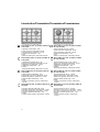
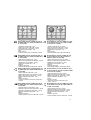
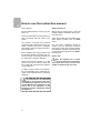
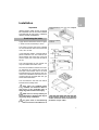
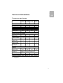
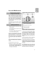
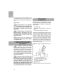
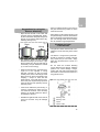
INSTALLATION INSTRUCTIONS
AND RECOMMENDATIONS FOR USE AND MAINTENANCE
COOKING HOBS
EINBAU-ANLEITUNG UND EMPFEHLUNGEN
FÜR GEBRAUCH UND INSTANDHALTUNG
KOCHFELDER
INSTRUCTIONS POUR L’INSTALLATION
ET RECOMMANDATIONS D’UTILISATION ET D’ENTRETIEN
PLAQUES DE CUISSON
ISTRUZIONI PER L’INSTALLAZIONE
E RACCOMANDAZIONI D’USO E MANUTENZIONE
PIANI COTTURA
EM/60 4G AI TR TV
EM/60 4G AI TR
EM/60 3G 1P AI TR TV
EM/60 3G 1P AI TR
EM/60 4G AI TR TV (FUND)
EM/60 4G AI TR (FUND)
EM/60 3G 1P AI TR TV (FUND)
EM/60 3G 1P AI TR (FUND)
-
EM/60
EM/60
EM/60
EM/60
EM/60
EM/60
EM/60
EM/60
4G
4G
3G
3G
4G
4G
3G
3G
AI AL TR TV
AI AL TR
1P AI AL TR TV
1P AI AL TR
AI AL TR TV (FUND)
AI AL TR (FUND)
1P AI AL TR TV (FUND)
1P AI AL TR (FUND)
Index
Inhaltsverzeichnis
GB
DE
Introduction
User Guide
Page 4
6
Installation
Positioning the hobs
Positioning the fan-assisted oven
Fastening the hob
Connecting the gas
Connecting the electricity
Gas conversion
7
7
8
8
8
9
9
Präsentation
Hinweise zum Gebrauch
Einbau
Einbauort für die Kochfelder
Einbauort für den Umluftofen
Verankerung des Kochfelds
Gasanschluss
Elektrischer Anschluss
Umstellung auf andere Gasart
Seite 4
20
21
21
22
22
22
23
23
Technical information
Dimensions and power
Technical details
11
11
12
Technische Angaben
25
Abmessungen und Leistungsmerkmale 25
Technische Daten
26
Use and Maintenance
Before starting for the first time
Igniting the burners
Protection mechanism against
inadvertently turning the gas controls
Components of an appliance
with built-in safety
Suggestions for effective use
of the burners
Cleaning and care the burners
Maintaining the burners
Operation of models
with electric hotplates
Suggestions for effective use
of the electric hotplates
Cleaning and care of the hotplates
Using the cover
13
13
13
27
If something doesn’t work
19
Gebrauch und Instandhaltung
Besondere Vorbedingungen für
die Inbetriebnahme
Zünden der Gasbrenner
Schutz gegen versehentliches
Drehen der Gashähne
Bestandteile eines Systems
für sicheren Gebrauch
Tipps für den korrekten Gebrauch
der Gasbrenner
Reinigung und Konservierung
der Gasbrenner
Wartung der Gaskochplatten
Funktionsweise der Modelle
mit elektrischen Kochzonen
Tipps für den korrekten Gebrauch
der elektrischen Kochzonen
Reinigung und Pflege der
Kochzonen
Gebrauch des Deckels
Im Störungsfall
33
2
14
14
15
15
16
16
17
17
18
27
27
28
28
29
29
30
30
31
31
32
Table des matiéres
Indice
FR
IT
Présentation
Guide d’utilisation
Page 4
34
Installation
Logement des tables
de cuisson
Logement du four
Encrage de la table de cuisson
Raccordement au gaz
Branchement électrique
Adaptation du gaz
35
Caractéristiques techniques
Dimensions et puissances
Caractéristiques techniques
39
39
40
Utilisation et entretien
Conditions spéciales avant la
mise en marche
Allumage des brûleurs
Système de blocage des
commandes de gaz
Composants d’un système
de sécurité
Recommandations pour une
bonne utilisation des brûleurs
Nettoyage et stockage
des brûleurs
Entretien des brûleurs
Fonctionnement des modèles
avec plaques électriques
Recommandations pour une bonne
utilisation des plaques électriques
Nettoyage et entretien des
plaques
Utilisation du couvercle
41
35
36
36
36
37
37
41
41
42
42
43
43
44
44
45
45
46
Si quelque chose ne fonctionne pas 47
Presentazione
Guida per l’uso
Pagina 4
48
Installazione
Alloggiamento dei piani cottura
Alloggiamento del forno
Ancoraggio del piano cottura
Collegamento del gas
Collegamento elettrico
Trasformazione del gas
49
49
50
50
50
51
51
Informazioni tecniche
Dimensioni e potenze
Dati tecnici
53
53
54
Uso e manutenzione
Requisiti speciali prima della
messa in servizio
Accensione dei bruciatori
Sistema anti-apertura accidentale
dei comandi del gas
Componenti di un sistema
con dispositivo di sicurezza
Consigli per un uso corretto
dei bruciatori
Pulizia e conservazione
dei bruciatori
Manutenzione dei bruciatori
Funzionamento dei modelli
con piastre elettriche
Consigli per un uso corretto
delle piastre elettriche
Pulizia e conservazione
delle piastre
Utilizzo del coperchio
55
Se qualcosa non funziona
61
55
55
56
56
57
57
58
58
59
59
60
3
Introduction/Präsentation/Présentation/Presentazione
1
3
GB
1
2
5
3
4
Models EM/60 4G AI AL TR (FUND) and EM/60 4G
AI TR (FUND)
Modelle EM/60 4G AI AL TR (FUND) und EM/60 4G
AI TR (FUND)
3G 1P AI TR (FUND)
1 Electric hotplate Ø 145 mm, 1500 W.
2 Triple crown burner 3,268 Kcal/h - 3.8 kW.
3 Semi-rapid burner 1,500 Kcal/h -1.75 kW.
4 Auxiliary burner 860 Kcal/h - 1 kW.
5 Grid.
* Maximum calorific power: 5,628 Kcal/h -6.55 kW.
DE Modelle EM/60 3G 1P AI AL TR (FUND) und EM/60
3G 1P AI TR (FUND)
1 Elektro-Kochzone mit Ø 145 mm, 1500 W
2 Brenner mit Dreifachkranz 3268 kcal/h - 3,8 kW
3 Mittelbrenner mit 1500 kcal/h -1,75 kW
4 Hilfsbrenner mit 860 kcal/h - 1 kW
5 Stellrost
* Maximale Wärmeleistung: 5.628 Kcal/h -6,55 kW.
1 Stark-Brenner mit 2580 kcal/h - 3 kW
2 Brenner mit Dreifachkranz 3268 kcal/h -3,8 kW
3 Mittelbrenner mit 1500 kcal/h -1,75 kW
4 Hilfsbrenner mit 860 kcal/h - 1 kW
5 Stellrost
* Maximale Wärmeleistung: 8208 Kcal/h - 9,55 kW.
FR
Modèles EM/60 4G AI AL TR (FUND) et EM/60 4G
AI TR (FUND)
FR Modèles EM/60 3G 1P AI AL TR (FUND) et EM/60
3G 1P AI TR (FUND)
1 Plaque électrique Ø 145 mm., 1.500 W.
2 Brûleur triple couronne 3.268 Kcal/h -3,8 kW.
3 Brûleur semi-rapide de 1.500 Kcal/h -1,75 kW.
4 Brûleur auxiliaire de 860 Kcal/h - 1 kW.
5 Grille.
* Puissance calorifique maximale: 5.628 Kcal/h 6,55 kW.
1 Brûleur rapide de 2.580 Kcal/h - 3 kW.
2 Brûleur triple couronne de 3.268 Kcal/h -3,8 kW.
3 Brûleur semi-rapide de 1.500 Kcal/h -1,75 kW.
4 Brûleur auxiliaire de 860 Kcal/h - 1 kW.
5 Grille.
* Puissance calorifique maximale: 8.208 Kcal/h 9,55 kW.
IT
Modelli EM/60 4G AI AL TR (FUND) e EM/60 4G AI
TR (FUND)
1 Bruciatore rapido da 2.580 Kcal/h - 3 kW.
2 Bruciatore a tripla corona da 3.268 Kcal/h - 3,8 kW.
3 Bruciatore semirapido da 1.500 Kcal/h - 1,75 kW.
4 Bruciatore ausiliario da 860 Kcal/h - 1 kW.
5 Griglia.
* Potenza calorifica massima: 8.208 Kcal/h - 9,55 kW.
4
4
GB Models EM/60 3G 1P AI AL TR (FUND) and EM/60
1 Rapid burner 2,580 Kcal/h - 3 kW.
2 Triple crown burner 3,268 Kcal/h -3.8 kW.
3 Semi-rapid burner 1,500 Kcal/h -1.75 kW.
4 Auxiliary burner 860 Kcal/h - 1 kW.
5 Grid.
* Maximum calorific power: 8,208 Kcal/h -9.55 kW.
DE
2
5
IT
Modelli EM/60 3G 1P AI AL TR (FUND) e EM/60 3G
1P AI TR (FUND)
1 Piastra elettrica Ø 145 mm, 1.500 W.
2 Bruciatore a tripla corona 3.268 Kcal/h - 3,8 kW.
3 Bruciatore semirapido da 1.500 Kcal/h - 1,75 kW.
4 Bruciatore ausiliario da 860 Kcal/h - 1 kW.
5 Griglia.
* Potenza calorifica massima: 5.628 Kcal/h 6,55 kW.
6
1
3
GB
2
5
3
4
Models EM/60 4G AI TR TV, EM/60 4G AI AL TR
TV, EM/60 4G AI TR TV (FUND) and EM/60 4G AI
AL TR TV (FUND)
GB
Modelle EM/60 4G AI TR TV, EM/60 4G AI AL TR
TV, EM/60 4G AI TR TV (FUND) und EM/60 4G AI
AL TR TV (FUND)
DE
Modèles EM/60 4G AI TR TV, EM/60 4G AI AL TR
TV, EM/60 4G AI TR TV (FUND) et EM/60 4G AI AL
TR TV (FUND)
FR
Modelli EM/60 4G AI TR TV, EM/60 4G AI AL TR
TV, EM/60 4G AI TR TV (FUND) e EM/60 4G AI AL
TR TV (FUND)
1 Bruciatore rapido da 2.580 Kcal/h - 3 kW.
2 Bruciatore a tripla corona da 3.268 Kcal/h - 3,8 kW.
3 Bruciatore semirapido da 1.500 Kcal/h - 1,75 kW.
4 Bruciatore ausiliario da 860 Kcal/h - 1 kW.
5 Griglia.
6 Supporto coperchio.
* Potenza calorifica massima: 8.208 Kcal/h - 9,55 kW.
Models EM/60 3G 1P AI TR TV, EM/60 3G 1P AI AL
TR TV, EM/60 3G 1P AI TR TV (FUND) and EM/60
3G 1P AI AL TR TV (FUND)
Modelle EM/60 3G 1P AI TR TV, EM/60 3G 1P AI
AL TR TV, EM/60 3G 1P AI TR TV (FUND) und
EM/60 3G 1P AI AL TR TV (FUND)
Modèles EM/60 3G 1P AI TR TV, EM/60 3G 1P AI
AL TR TV, EM/60 3G 1P AI TR TV (FUND) et EM/60
3G 1P AI AL TR TV (FUND)
1 Plaque électrique Ø 145 mm, 1.500 W.
2 Brûleur à triple couronne 3.268 Kcal/h - 3,8 kW.
3 Brûleur semi-rapide de 1.500 Kcal/h -1,75 kW.
4 Brûleur auxiliaire de 860 Kcal/h - 1 kW.
5 Grille.
6 Support couvercle.
* Puissance calorifique maximale: 5.628
Kcal/h - 6,55 kW.
1 Brûleur rapide de 2.580 Kcal/h - 3 kW.
2 Brûleur triple couronne de 3.268 Kcal/h - 3,8 kW.
3 Brûleur semi-rapide de 1.500 Kcal/h - 1,75 kW.
4 Brûleur auxiliaire de 860 Kcal/h - 1 kW.
5 Grille.
6 Support couvercle.
* Puissance calorifique maximale: 8.208 Kcal/h 9,55 kW.
IT
4
1 Elektro-Kochzone mit Ø 145 mm, 1500 W
2 Brenner mit Dreifachkranz 3268 kcal/h - 3,8 kW
3 Mittelbrenner mit 1500 kcal/h -1,75 kW
4 Hilfsbrenner mit 860 kcal/h - 1 kW
5 Stellrost
6 Halterung für Deckel
* Maximale Wärmeleistung: 5.628 Kcal/h -6,55 kW.
1 Stark-Brenner mit 2580 kcal/h - 3 kW
2 Brenner mit Dreifachkranz mit 3268 kcal/h - 3,8 kW
3 Mittelbrenner mit 1500 kcal/h - 1,75 kW
4 Hilfsbrenner mit 860 kcal/h - 1 kW
5 Stellrost
6 Halterung für Deckel
* Maximale Wärmeleistung: 8208 Kcal/h - 9,55 kW.
FR
2
5
1 Electric hotplate Ø 145 mm, 1500 W.
2 Triple crown burner 3,268 Kcal/h - 3.8 kW.
3 Semi-rapid burner 1,500 Kcal/h -1.75 kW.
4 Auxiliary burner 860 Kcal/h - 1 kW.
5 Grid.
6 Cover support.
* Maximum calorific power: 5,628 Kcal/h -6.55 kW.
1 Rapid burner 2,580 Kcal/h - 3 kW.
2 Triple crown burner 3,268 Kcal/h - 3.8 kW.
3 Semi-rapid burner 1,500 Kcal/h -1.75 kW.
4 Auxiliary burner 860 Kcal/h - 1 kW.
5 Grid.
6 Cover support.
* Maximum calorific power: 8,208 Kcal/h -9.55 kW.
DE
1
6
IT
Modelli EM/60 3G 1P AI TR TV, EM/60 3G 1P AI AL
TR TV, EM/60 3G 1P AI TR TV (FUND) e EM/60 3G
1P AI AL TR TV (FUND)
1 Piastra elettrica Ø 145 mm, 1.500 W.
2 Bruciatore a tripla corona 3.268 Kcal/h - 3,8 kW.
3 Bruciatore semirapido da 1.500 Kcal/h - 1,75 kW.
4 Bruciatore ausiliario da 860 Kcal/h - 1 kW.
5 Griglia.
6 Supporto coperchio.
* Potenza calorifica massima: 5.628 Kcal/h - 6,55 kW.
5
GB
How to use the instruction manual
Dear customer,
We are delighted that you have put your
trust in us.
We are confident that the new hob that you
have purchased will fully satisfy your
needs.
This modern, functional and practical
model has been manufactured using topquality materials that have undergone
strict quality controls throughout the manufacturing process.
Before installing and using it, please read
this Manual carefully and follow the instructions closely, as this will guarantee better results when using the appliance.
Keep this Instruction Manual in a safe
place so that you can refer to it easily and
thus comply with the terms and conditions
of the guarantee.
In order to make a claim on this Guarantee, it is essential that you submit the purchase receipt together with the guarantee
certificate.
You should keep the Guarantee
Certificate or, where relevant, the technical datasheet, together with the Instruction Manual for the duration of the
service life of the appliance. It has
important technical information about
the appliance.
6
Safety instructions
Before using for the first time, you should
carefully read the installation and connection instructions.
These hob models may be installed in the
same kitchen furniture units as TEKA
ovens.
For your safety, installation should be
carried out by an authorised technician
and should comply with existing installation standards. Likewise, any internal work
on the hob should only be done by TEKA’s
technical staff.
Please note:
When the hotplates are in operation or have recently been in operation,
some areas will be hot and can burn.
Children should be kept well away.
Installation
Important
GB
Minimum distances
to walls
fig. 1
INSTALLATION AND SETUP SHOULD
BE CARRIED OUT BY AN AUTHORISED
TECHNICIAN IN LINE WITH CURRENT
INSTALLATION STANDARDS.
Positioning the hobs
A gap with the dimensions shown in figure
1 will be cut into the worktop or stove.
The system for fixing the hob is intended
for use with kitchen units with a thickness
of 20, 30 or 40 mm.
In free-standing models, a shelf should be
placed inside the unit. The minimum distance between the lower part of the hob
and the upper part of the shelf should be
20 mm.
Minimum ventilation
distances
40 mm minimum
40 mm minimum
The hobs described in this manual can
only be installed with TEKA ovens.
The minimum distance between the surface supporting the cooking pans and the
lower part of the kitchen unit or the hood
located above the hob should be 650 mm.
If the hood’s installation instructions recommend that the gap is greater than this, you
should follow this advice.
The unit where the hob and oven will be
located will be suitably fixed.
OVEN
Installation
space
xim
ma
um
When hobs are handled before
being installed, care should be taken in
case there is any protruding part or
sharp edge which could cause injury.
TEKA does not accept liability for
any malfunction or damage that may be
caused by faulty installation.
The glues used in manufacturing
the kitchen unit and in the adhesive on
the decorative laminate of the worktop
surface should be made to tolerate temperatures of up to 100ºC.
7
GB
The glass covers can shatter when
they heat up. Turn off the burners before
closing the cover.
fig. 2
Positioning the oven
See the corresponding manual.
40 mm
Fixing the hob
When the gap has been properly sized,
the sealing washer (J) should be put on
the part of the cooker.
30 mm
Position the clips (K) as shown in figure 2,
fastening them to the openings in the
lower part of the body using the metal threaded screws provided (Ø 4.2 mm).
The clips (K) and the sealing washer (J)
are provided, and can be found in the packaging.
For worktop thicknesses of less than 30
mm., use the self-tapping screws (M) that
are provided as a fastening accessory - put
them into the clip’s round hole. This hole will
be threaded as the screw is inserted into it,
and this should be done before fixing the
clip to the worktop.
Connecting the gas
Connecting the hob to the gas mains
should be done in compliance with the
current installation standards and regulations.
Ventilation slots should also be made at
the site in compliance with current norms.
The hob is provided with a threaded connection 1/2” in diameter, in line with ISO
228-1. A Ø 10/12 mm copper pipe is provided as an accessory for welding the gas
inlet pipe.
8
20 mm
Whenever the gas connection nut is removed, its washer should be changed.
In order that the hob is not damaged by
tightening the nut on the gas connection
pipe, a maximum torque of 350 cm * Kgf
should be applied.
When the gas connection has been made,
the installation should be checked to ensure that it is completely sealed. If the check
is done using air, care should be taken that
the test pressure is no more than 200
gr./cm2. Where air is not available, soapy
water should be applied to ensure that
there are no leaks in the connections. Testing should never be done using a
flame.
When the hob has been installed, check
that the burner minimums are properly
GB
adjusted. To do this, light the burners and
check that they do not go out if you switch
quickly from the maximum to the minimum.
Connecting the electricity
Before connecting the hob to the electric
mains, check that the voltage and frequency of the mains matches that shown
on the hob’s rating plate, which is located
lower down, and on the guarantee certificate or, where appropriate, the technical
datasheet supplied, which should be kept
together with this manual.
The connection is made via an omnipolar
switch or plug where accessible, which is
suitable for the intensity to be tolerated
and which has a minimum gap of 3 mm
between its contacts, which will ensure
disconnection in case of emergency or
when cleaning the hob.
The connection should include correct earthing, in compliance with current norms.
If the flexible supply cable fitted to these
appliances ever needs to be changed, it
should be replaced by TEKA’s official SAT
cable, which requires special tools.
The input cable should not be in contact
either with the body of the hob or with the
body of the oven, if the oven is installed in
the same unit.
Gas conversion
Important!
Any alteration that is to be made to the
appliance to convert it to a different
type of gas should only be carried out
by an authorised person and should
comply with current standards.
Information for Technical Assistance: whenever the type of gas or the
appliance’s pressure is changed, the new
regulation plate should be placed on top of
the old one so that the new features can
be seen after the change.
The tasks involved in conversion are:
* Replace the injectors.
* Adjust the taps’ minimums.
The injectors required for each gas type
are shown in table 1.
To replace the injectors, follow these instructions:
1 Remove the grids and upper parts of the
burner so that the injector can be seen.
2 Using a number 7 pipe spanner, remove
the injectors and replace them with the
new ones. Ensure that the injector is
properly tightened and so avoid gas
escaping.
3 Replace the grid and burners that were
previously removed.
When the injectors have been changed,
adjust the minimums as follows:
1 Turn the burners on to their minimum.
9
GB
2 Remove the cooker’s controls in order to
be able to access the gas taps.
3 Use a slim, grooved screwdriver to turn
the screw located to the left or in the
centre of the gas tap’s shaft (the flame
increases when you turn to the left and
decreases when you turn to the right).
4 When properly adjusted, check that the
flame does not go out when you turn the
knob quickly from maximum to minimum.
TEKA INDUSTRIAL, S.A. does not accept
liability for any hob malfunction if the gas
conversion or the adjustment of the burners’ minimums has not been carried out
by TEKA’s official personnel.
Table 1
Burner
Family
Second
Third
Group H
Group 3+
Triple crown
130
97
Rapid
116
85
Semi-rapid
97
66
Auxiliary
72
50
Ø injector expressed in 1/100 mm.
10
Technical Information
GB
Dimensions and power
Models
EM/60
EM/60
4G AI AL TR 3G 1P AI AL
(FUND)
TR (FUND)
EM/60
4G AI TR
(FUND)
EM/60
3G 1P AI TR
(FUND)
Hob dimensions
Height (mm)
90
90
90
90
Length (mm)
600
600
600
600
Width (mm)
510
510
510
510
Dimensions of the positioning in the unit
Length (mm)
560
560
560
560
Width (mm)
480
480
480
480
Depth (mm)
40
40
40
40
Power per burner and hotplate
Rapid gas
1
burner 3 kW.
1
Semi-rapid gas
1
1
1
burner 1.75 kW.
1
Auxiliary gas
1
1
1
burner 1 kW.
1
Triple crown gas
burner 3.8 kW.
1
1
1
1
Electric hotplate
1
Ø 145 mm,
1
1,500 W
Electric:
Nominal Power
(W) for 230V*
0.6
1,500
0.6
1,500
Supply
SEE THE APPLIANCE’S RATING PLATE
voltage (V)
Frequency (Hz)
50 - 60
50 - 60
50 - 60
50 - 60
Gas:
Maximum power kW
9.55
6.55
9.55
6.55
* For voltages other than 230 V please consult the rating plate
on the appliance.
11
GB
Technical details
COMMON FEATURES FOR ALL MODELS
WITH ELECTRIC HOTPLATES AND AUTOMATIC IGNITION
The supply voltage and frequency will be
as shown on the rating plate.
If an electric hotplate gets cracked, the
hob should be disconnected from the electricity supply.
COMMON FEATURES FOR
MODELS WITH GAS BURNERS
clear, a window opened, or an effective
mechical ventilation system device,
such as a hood, installed.
The intense and prolonged use of
the appliance may call for complementary ventilation, such as opening a window, or more efficient ventilation such
as increasing the power of the mechanical ventilation if this exists.
Class 3 hob.
You should keep the Guarantee Certificate or, where relevant, the
technical datasheet, together with
the Instruction Manual for the duration of the service life of the appliance. It has important technical information about the appliance.
ALL
Warnings:
a) Before installation, make sure that the
local supply conditions (the gas type and
pressure) are compatible with the appliance’s setup.
b) The setup conditions for this appliance
are written on the label (or the rating
plate).
c) This appliance should not be connected
to a device for removing combustion products. It should be installed and connected
in compliance with the current installation
standards. Special attention should be paid
to the regulations applying to ventilation.
Table 2
A gas cooking appliance produces
heat and moisture at the site where it is
installed. The kitchen should be provided with suitable ventilation: natural
ventilation sources should be kept
Table 3
Nominal consumption*
Spain
II2H3+
Portugal
II2H3+
United Kingdom
II2H3+
Switzerland
II2H3+
Ireland
II2H3+
Chez Republic
II2H3+
Greece
I3+
Hungary
I2H
Denmark
I2H
Norway
I2H
Finland
I2H
Sweden
I2H
Triple crown
Burner
Nominal Calorific Consumption
Category
Country
Rapid
Semi-rapid Auxiliary
kW
mbar
3.8
3
1.75
1
G-20 (Nm3/h)
20
0.36
0.29
0.17
0.10
G-30 (Kg/h)
29
0.28
0.22
0.13
0.07
G-31 (Kg/h)
37
0.27
0.21
0.13
0.07
Reduced calorific consumption
kW
1.55
0.77
0.47
0.33
Performance
%
>52
>52
>52
-
* Consumption over Gross Calorific Value (Hs )
12
Use and Maintenance
Special measures before
using for the first time
GB
fig. 3
Before connecting the hob to the electric
mains, check that the voltage and frequency of the mains matches that shown
on the hob’s rating plate, which is located
lower down, and on the guarantee or,
where appropriate, the technical datasheet supplied, which should be kept together
with this manual.
Remember that you may have to remove
the protective plastic cover that is stuck to
the hob.
Igniting the burners
* Make sure that the knobs are in their
correct position.
‘Burner in operation’ indicator
Knob position when not in use
Maximum gas position
Minimum gas position
* Turn on the gas at the mains or turn the
gas cylinder tap.
* Put a flame or spark to the burner if you
do not have automatic ignition.
Press the control knob and at the same
time turn it anti-clockwise to the maximum
position (the big flame, “C” in figure 3). The
burner will now come on at full power;
then, if you wish, you can turn the knob to
the minimum position (the small flame,
“D”).
With hob models that have automatic ignition and the safety feature, proceed as
follows:
1. Press down the burner control.
2. Keeping the burner control pressed
down, turn it all the way till the gas ignites, and keep it pressed down for at
least 2 seconds so that the safety thermocouple can take effect.
3. Set the control to the position required.
In order for the automatic ignition system
to work properly, it is vital that the ignition
(the ceramic and the electrode) is cleaned
regularly and carefully - this will avoid ignition problems. Check, too, that the grooves in the burners have not become obstructed.
On the control panel, areas are marked (A)
that show the control for each burner.
If a gas smell is detected, the gas intake to
the hob should be shut off and the room
ventilated. The gas installation and the hob
should also be checked by a specialised
technician.
Use flat-bottomed pans and check that
they sit squarely on the grid, so that when
food boils the pan does not slip (do not use
pans with a concave or convex base).
13
GB
Safety system
components
Only pans with a minimum diameter of 140
mm. should be used. If you wish to use a
smaller pan, always use the auxiliary burner.
Please note:
When the burners are in operation
or have recently been in operation, the
hob will be hot in places and this can
lead to burns. Children should be kept
well away.
For safety reasons, we advise that
the instructions provided by the gas
supply company are followed and that
the supply tap is turned off when the
hob is not in use.
The glass covers can shatter when
they heat up. Turn off the burners before
closing the cover.
Protection mechanism against
inad-vertently turning the
gas controls
On hobs with the safety feature (those
models which have the letters AL), the gas
cut-off device is made up of these elements below:
* The safety tap
* The safety thermocouple, next to the
burner
* The thermocouple-tap connection
The thermocouple sends an electric signal
to the tap which identifies whether the burner has a flame. During ignition, the tap
should be held down for around two
seconds, until the thermocouple has heated up and can send a satisfactory electric
signal to the tap. Should the burner go out,
the absence of a flame is detected by the
thermocouple, which makes the safety tap
cut off the flow of gas.
fig. 4
On models without the safety
system (without the gas cut-off device),
the gas taps are equipped with a mechanical system that prevents the controls from
being freely turned from the off position to
the on position (and, therefore, prevents
any accidental escape of gas from the burners) if the control has not previously
been pressed down.
If at any time while using the hob
you notice that a control can be turned
from the off position without it needing
to be pressed down beforehand (for
example: because of dirt which may
have got into and accumulated in the
gas taps) you should, for your own
safety, quickly notify the technical service so that the problem can be rectified.
14
Safety thermocouple
Thermocouple-tap connection
Spark generation connection
Ignition spark plug
Safety tap
GB
Suggestions for using the
burners effectively
* Rapid burners should not be used with
pans that have a small diameter, because part of the flame will spread away from
the pan, thus reducing performance significantly (see figure 5).
Right
* Cast iron plates should not be used on
the grid, because they reflect too much
heat onto the hob.
* Pans placed on the burners should not jut
out past the edge of the hob, because the
effect of the flame being reflected from the
pan can damage hobs whose surfaces
are not resistent to high temperatures.
Cleaning and care
of the burners
fig. 5
Wrong
* The grids should be cleaned with a nonabrasive scourer when they have cooled
down.
* The burners should not be operated
without there being a pan on them, or gas
will be wasted and the grid will heat up
excessively. The pan should be covered
up, in order to save energy.
* When the burners are in operation, they
ought not to be exposed to strong
draughts, because as well as losing
calorific power, there is the danger of the
flame going out, which would lead to gas
escaping - except on hobs with the
safety feature - and could cause an accident. This point is particularly important
when the burners are operating at their
minimum power.
* The burners - the grooves in particular should be cleaned at regular intervals;
they should be put into warm, soapy
water and cleaned with a scourer or a
stiff brush.
* Do not clean the enamel diffusing
covers while they are still hot. Abrasive
products can cause damage: vinegar,
coffee, milk, salt water and tomato juice
that remain on the enamel surfaces for a
long period of time.
fig. 6
* If the burner makes the pans smoky, or
if the tip of the flame is yellow, the burner should be cleaned. If this anomaly
persists, you should contact the Technical Assistance Service.
* Griddles and grills should not be used to
cook on a low heat - they can damage
the hob.
Diffusing cover
Diffusing crown
Injector
Injector holder
15
GB
* The stainless steel should be washed in
soapy water using a soft cloth. If the
metal is yellowish after washing, we
recommend that you use: lemon, vinegar, dilute amonia or a cleaning product
that contains dilute amonia.
* When cleaning the appliance with the
burners removed, care should be taken
not to allow liquid or other objects to get
into the injector openings.
* When cleaning, do not use products that
can harm aluminium, such as soda, oil,
etc.
ded by the appliance should be made
by authorised technical personnel.
Operation of models with
electric hotplates
The electric hotplates are controlled by a
switch with seven positions. To get different levels of power, all you need to do is
to turn the appropriate knob and set it to
the position you want. On the control
panel, areas are marked (A) that show
(with a circle) the control for each hotplate.
fig. 7
*The ignition unit (ceramic part and electrode) must be periodically cleaned with
care in order to prevent ignition problems. A check should also be made
that the burner slots are not obstructed.
Note: Whenever you replace a burner,
you should check that all of the parts
are properly in place. A part that is not
in the right place can cause poor combustion and/or overheating.
Maintaining
the burners
Whenever the gas taps are removed, you
should change the washer that is between
the taps and the supply pipe. The burners
are working properly when their flame is
stable and a greeny-blue colour. If the tip
of the flame is yellow, the burners need to
be cleaned; if the problem persists, contact
the Technical Service.
In order to guarantee that the gas installation is properly sealed and that the burners
are working properly, the hob needs to be
inspected by specialised Technical Service
personnel at least once every 4 years.
Note: Any alteration or adjustment nee-
16
‘Hotplate in operation’ indicator
Control index
The pan should be placed on the hotplate
before ignition.
The power corresponding to each of the
switch’s positions is as follows:
GB
Control set to
0
1
2
3
4
5
6
Power
Hotplate Ø 145 -1500 W.
Switched off
135 W.
165 W.
250 W.
500 W.
750 W.
1500 W.
The Ø 145 mm 1500 W hotplate (the one
with the red dot) heats up rapidly and
achieves its maximum during around the
first five minutes, after which its power
decreases to 750 W, at which point the
temperature becomes constant.
When first connecting, or if the hotplate
has not been used for some time, the
moisture absorbed by the insulation needs
to be eliminated. To carry out this drying
process, turn the hotplate on - with no pan
on it - for five minutes at switch position 2.
The smell and smoke that are emitted,
while unpleasant, present no risk, and you
should assist ventilation by opening doors
and windows to let the outside air in.
Suggestions for effective
use of the electric hotplates
To ensure maximum performance from
your hob, follow these guidelines:
* Use pans with a flat base, as the greater
the surface contact between the pan
and the hotplate, the greater will be the
heat transmission. We recommend the
use of heavy pans so that the base is
more difficult to dent. The picture shows
how pans with battered or dented bases
have less surface contact. (see fig.8)
Right
Wrong
Wrong
fig. 8
* Do not use pans with a diameter that is
smaller than that of the hotplate, in order
to avoid boiling foods spilling over onto
the hotplates.
* Dry the bottom of your pans before putting them on the hotplates.
* When you are almost finished cooking, it
is a good idea to set the hotplate to the
minimum or to turn it off just before
removing the pan, in order to make use
of the energy that has been stored and
to avoid the hotplate operating while it is
empty.
Never use the electric hotplate
without a pan on it.
Cleaning and care
of the hotplates
* Disconnect the appliance from the electric mains before cleaning it.
* Do not use cleaning products that can
harm aluminium, such as soda, acids, etc.
* The electric hotplates should be cleaned
using soapy water and a non-abrasive
scourer. If, after cooking, you notice that
the hotplate’s or hob’s stainless steel rim
are yellowing slightly, you can counter
this by using lemon, vinegar, dilute amonia or any product containing dilute
amonia.
17
GB
* If liquids spill onto the hotplate, they
should be quickly removed using a
cloth. Never leave them to be burned on
the hotplate, for this will reduce heat
transmission considerably.
* If the hotplate is not going to be used for
some time, it should be oiled so that the
surface shines and rusting is avoided.
* Remember that the hotplate will have a
longer life if, where possible, moisture
and excessive temperatures are avoided.
* Steam-based appliances should not be
used to clean the hob.
Do not clean the hotplates while
they are still hot.
18
Using the cover
Models that have a glass cover should be
cleaned with warm water, without using
rough cloths or abrasive substances. To
make it easier to clean the rear part of the
hob, the cover can be taken off by lifting it up.
After cleaning, the cover should be carefully replaced.
Before the cover is opened, any liquids that
have been spilled should be cleaned up.
Do not close the cover when
the burners or the electric hotplate are ON or are still hot.
TEKA INDUSTRIAL S.A. reserves the
right to alter its appliances in any way it
deems necessary or useful while not altering its basic characteristics.
If something doesn’t work
GB
Before calling the Technical Service, please
make the following checks:
Fault
Possible cause
Possible solution
Neither the hotplates nor the pilot lights are working
Connect the cable
to the mains
The cable is not connected to the mains
There is no spark when the
automatic ignitiion control is pressed
There is no current at
the plug
Check/repair the electricity at the mains
There is a spark but the burner does not ignite
The spark plug and the part
of the burner where the
spark should be is soiled or
greasy
Clean the end of the
spark plug and the
burner
Gas is not coming through
to the hob
Check that the gas
cylinder tap is properly
open
The gas burners do not light
If it is piped gas, open
the gas tap
The burner ignites, however, when you release the knob
activating the safety feature, it goes out again
The flame does not appear
in the area heated by the
thermocouple
Clean the burner’s
openings
The gas burners are making the pans dirty
The burner openings
are dirty
Clean the burner
openings
The injector or injector
holder is dirty
Clean the porta-injector
and injector without
using anything which
could damage or alter
the diameter of the gas
outlet opening
19