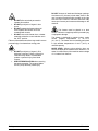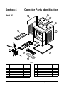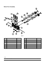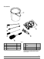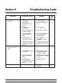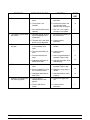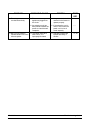
1
Model 161
Soft Serve Freezer
Original Operating Instructions
055155-M
8/14/08 (Original Publication)
(Updated 5/29/12
Complete this page for quick reference when service is required:
Taylor Distributor:
Address:
Phone:
Service:
Parts:
Date of Installation:
Information found on the data label:
Model Number:
Serial Number:
Electrical Specs:
Voltage
Cycle
Phase
Maximum Fuse Size:
A
Minimum Wire Ampacity:
A
E August, 2008 Taylor
All rights reserved.
055155--M
The word Taylor and the Crown design
are registered trademarks in the United States
of America and certain other countries.
Taylor Company
750 N. Blackhawk Blvd.
Rockton, IL 61072
Table of Contents
To the Installer . . . . . . . . . . . . . . . . . . . . . . . . . . . . . . . . . . . . . . . . . . . .
1
Installer Safety . . . . . . . . . . . . . . . . . . . . . . . . . . . . . . . . . . . . . . . . . . . . . . . . . . . . . . . .
1
Site Preparation . . . . . . . . . . . . . . . . . . . . . . . . . . . . . . . . . . . . . . . . . . . . . . . . . . . . . . .
1
Air Cooled Units . . . . . . . . . . . . . . . . . . . . . . . . . . . . . . . . . . . . . . . . . . . . . . . . . . . . . . .
1
Water Connections (Water Cooled Units Only) . . . . . . . . . . . . . . . . . . . . . . . . . . . .
2
Electrical Connections . . . . . . . . . . . . . . . . . . . . . . . . . . . . . . . . . . . . . . . . . . . . . . . . .
2
Electrical Hook--Up Installation
(60 Cycle, 1 Ph, Supplied With Cord and Plug) . . . . . . . . . . . . . . . . . . . . . . . . . . . .
3
To the Operator . . . . . . . . . . . . . . . . . . . . . . . . . . . . . . . . . . . . . . . . . . .
4
Compressor Warranty Disclaimer . . . . . . . . . . . . . . . . . . . . . . . . . . . . . . . . . . . . . . .
4
Section 3
Safety . . . . . . . . . . . . . . . . . . . . . . . . . . . . . . . . . . . . . . . . . . . . . . . . . . . .
5
Section 4
Operator Parts Identification . . . . . . . . . . . . . . . . . . . . . . . . . . . . . . .
7
Model 161 . . . . . . . . . . . . . . . . . . . . . . . . . . . . . . . . . . . . . . . . . . . . . . . . . . . . . . . . . . . .
7
Beater Door Assembly . . . . . . . . . . . . . . . . . . . . . . . . . . . . . . . . . . . . . . . . . . . . . . . . .
8
Accessories . . . . . . . . . . . . . . . . . . . . . . . . . . . . . . . . . . . . . . . . . . . . . . . . . . . . . . . . . .
9
Important: To the Operator . . . . . . . . . . . . . . . . . . . . . . . . . . . . . . . . .
10
Symbol Definitions . . . . . . . . . . . . . . . . . . . . . . . . . . . . . . . . . . . . . . . . . . . . . . . . . . . .
10
Operating Procedures . . . . . . . . . . . . . . . . . . . . . . . . . . . . . . . . . . . . .
13
Assembly . . . . . . . . . . . . . . . . . . . . . . . . . . . . . . . . . . . . . . . . . . . . . . . . . . . . . . . . . . . .
13
Sanitizing . . . . . . . . . . . . . . . . . . . . . . . . . . . . . . . . . . . . . . . . . . . . . . . . . . . . . . . . . . . .
16
Priming . . . . . . . . . . . . . . . . . . . . . . . . . . . . . . . . . . . . . . . . . . . . . . . . . . . . . . . . . . . . . .
18
Closing Procedure . . . . . . . . . . . . . . . . . . . . . . . . . . . . . . . . . . . . . . . . . . . . . . . . . . . .
18
Draining Product From the Freezing Cylinder . . . . . . . . . . . . . . . . . . . . . . . . . . . . .
18
Rinsing . . . . . . . . . . . . . . . . . . . . . . . . . . . . . . . . . . . . . . . . . . . . . . . . . . . . . . . . . . . . . .
19
Cleaning . . . . . . . . . . . . . . . . . . . . . . . . . . . . . . . . . . . . . . . . . . . . . . . . . . . . . . . . . . . . .
19
Disassembly . . . . . . . . . . . . . . . . . . . . . . . . . . . . . . . . . . . . . . . . . . . . . . . . . . . . . . . . . .
19
Brush Cleaning . . . . . . . . . . . . . . . . . . . . . . . . . . . . . . . . . . . . . . . . . . . . . . . . . . . . . . .
19
Section 1
Section 2
Section 5
Section 6
Table of Contents
Model 161
Table of Contents -- Page 2
Important: Operator Checklist . . . . . . . . . . . . . . . . . . . . . . . . . . . . . .
21
During Cleaning and Sanitizing . . . . . . . . . . . . . . . . . . . . . . . . . . . . . . . . . . . . . . . . .
21
Troubleshooting Bacterial Count . . . . . . . . . . . . . . . . . . . . . . . . . . . . . . . . . . . . . . . .
21
Regular Maintenance Checks . . . . . . . . . . . . . . . . . . . . . . . . . . . . . . . . . . . . . . . . . . .
21
Winter Storage . . . . . . . . . . . . . . . . . . . . . . . . . . . . . . . . . . . . . . . . . . . . . . . . . . . . . . . .
22
Section 8
Troubleshooting Guide . . . . . . . . . . . . . . . . . . . . . . . . . . . . . . . . . . . .
23
Section 9
Parts Replacement Schedule . . . . . . . . . . . . . . . . . . . . . . . . . . . . . . .
26
Section 10
Parts List . . . . . . . . . . . . . . . . . . . . . . . . . . . . . . . . . . . . . . . . . . . . . . . . .
27
Wiring Diagrams . . . . . . . . . . . . . . . . . . . . . . . . . . . . . . . . . . . . . . . . . . . . . . . . . . . . . .
36
Section 7
Note: Continuing research results in steady improvements; therefore, information
in this manual is subject to change without notice.
Note: Only instructions originating from the factory or its authorized translation
representative(s) are considered to be the original set of instructions.
E August, 2008 Taylor (Original Publication)
(Updated May, 2012)
All rights reserved.
055155--M
The word Taylor and the Crown design
are registered trademarks in the United States
of America and certain other countries.
Model 161
Taylor Company
750 N. Blackhawk Blvd.
Rockton, IL 61072
Table of Contents
Section 1
To the Installer
Site Preparation
The following are general installation instructions. For
complete installation details, please see the check out
card.
Installer Safety
Review the area where the unit will be installed before
uncrating the unit. Make sure that all possible hazards
to the user and the equipment have been addressed.
In all areas of the world, equipment should be
installed in accordance with existing local codes.
Please contact your local authorities if you have any
questions.
For Indoor Use Only: This unit is designed to operate
indoors, under normal ambient temperatures of
70_-75_F (21_-24_C). The freezer has successfully
performed in high ambient temperatures of
104_(40_C) at reduced capacities.
Care should be taken to ensure that all basic safety
practices are followed during the installation and
servicing activities related to the installation and
service of Taylor equipment.
S
S
S
S
This unit must NOT be installed in an area
where a water jet or hose can be used. NEVER use a
water jet or hose to rinse or clean the unit. Failure to
follow this instruction may result in electrocution.
Only authorized Taylor service personnel
should perform installation and repairs on
the equipment.
Authorized service personnel should consult
OSHA Standard 29CFRI910.147 or the
applicable code of the local area for the
industry standards on lockout/tagout
procedures before beginning any installation
or repairs.
Authorized service personnel must ensure
that the proper PPE is available and worn
when required during installation and
service.
Authorized service personnel must remove
all metal jewelry, rings, and watches before
working on electrical equipment.
This unit must be installed on a level surface
to avoid the hazard of tipping. Extreme care should be
taken in moving this equipment for any reason. Two or
more persons are required to safely move this unit.
Failure to comply may result in personal injury or
equipment damage.
Uncrate the unit and inspect it for damage. Report any
damage to your Taylor Distributor.
This piece of equipment is made in the USA and has
USA sizes of hardware. All metric conversions are
approximate and vary in size.
The main power supply(s) to the freezer must
be disconnected prior to performing any repairs.
Failure to follow this instruction may result in personal
injury or death from electrical shock or hazardous
moving parts as well as poor performance or damage
to the equipment.
Air Cooled Units
Note: All repairs must be performed by an
authorized Taylor Service Technician.
DO NOT obstruct air intake and discharge openings:
This unit has many sharp edges that can
cause severe injuries.
The Model 161 requires 6” (152 mm) on both sides,
and 0” at the rear. Install the skirt provided on the right
side of the unit. Minimum air clearances must be met
to assure adequate air flow for optimum performance.
081208
Model 161
1
To the Installer
Water Connections
(Water Cooled Units Only)
CAUTION: THIS EQUIPMENT MUST BE
PROPERLY GROUNDED! FAILURE TO DO SO
CAN RESULT IN SEVERE PERSONAL INJURY
FROM ELECTRICAL SHOCK!
An adequate cold water supply must be provided with
a hand shut--off valve. On the underside rear of the
base pan, two 3/8” I.P.S. water connections for inlet
and outlet have been provided for easy hook--up. 1/2”
inside diameter water lines should be connected to the
machine. (Flexible lines are recommended, if local
codes permit.) Depending on local water conditions, it
may be advisable to install a water strainer to prevent
foreign substances from clogging the automatic water
valve. There will be only one water “in” and one water
“out” connection. DO NOT install a hand shut--off valve
on the water “out” line! Water should always flow in this
order: first, through the automatic water valve; second,
through the condenser; and third, through the outlet
fitting to an open trap drain.
This unit is provided with an equipotential
grounding lug that is to be properly attached to the rear
of the frame by the authorized installer. The installation
location is marked by the equipotential bonding
symbol (5021 of IEC 60417-1) on both the removable
panel and the equipments frame.
S
A back flow prevention device is required
on the incoming water connection side. Please
refer to the applicable National, State, and local codes
for determining the proper configuration.
Electrical Connections
S
Each unit requires one power supply for each data
label on the unit. Check the data label(s) on the freezer
for branch circuit overcurrent protection or fuse, circuit
ampacity, and other electrical specifications. Refer to
the wiring diagram provided inside of the electrical box
for proper power connections.
In the United States, this equipment is intended to be
installed in accordance with the National Electrical
Code (NEC), ANSI/NFPA 70--1987. The purpose of
the NEC code is the practical safeguarding of persons
and property from hazards arising from the use of
electricity. This code contains provisions considered
necessary for safety. Compliance therewith and
proper maintenance will result in an installation
essentially free from hazard!
S
In all other areas of the world, equipment should be
installed in accordance with the existing local codes.
Please contact your local authorities.
Stationary appliances which are not
equipped with a power cord and a plug or
another device to disconnect the appliance
from the power source must have an all-pole
disconnecting device with a contact gap of
at least 3mm installed in the external
installation.
Appliances that are permanently connected
to fixed wiring and for which leakage
currents may exceed 10 mA, particularly
when disconnected or not used for long
periods, or during initial installation, shall
have protective devices such as a GFI, to
protect against the leakage of current,
installed by the authorized personnel to the
local codes.
Supply cords used with this unit shall be
oil-resistant, sheathed flexible cable not
lighter than ordinary polychloroprene or
other equivalent synthetic
elastomer-sheathed cord (Code designation
60245 IEC 57) installed with the proper cord
anchorage to relieve conductors from strain,
including twisting, at the terminals and
protect the insulation of the conductors from
abrasion.
FOLLOW YOUR LOCAL ELECTRICAL CODES!
101012
To the Installer
2
Model 161
Electrical Hook--Up Installation
Refrigerant
(60 Cycle, 1 Ph, Supplied With Cord and Plug)
This freezer is supplied with a 3--wire cord and
grounding type plug for connection to a single phase,
60 cycle, branch circuit supply. This unit must be
plugged into a properly grounded receptacle. The cord
and plug provided for 208/230/60/1, is 20A; therefore
the wall outlet must also be 20A. Check the data label,
located on the side panel, for electrical specifications.
In consideration of our environment, Taylor
proudly uses only earth friendly HFC refrigerants. The
HFC refrigerant used in this unit is R404A. This
refrigerant is generally considered non-toxic and
non-flammable, with an Ozone Depleting Potential
(ODP) of zero (0).
Permanent wiring may be employed if required by local
codes. Instructions for conversion to permanent wiring
are as follows:
1.
Be sure the freezer is electrically disconnected.
2.
Remove the appropriate panel and locate the
small electrical box at the base of the freezer.
3.
Remove the factory--installed cord and strain
relief bushing.
4.
Route incoming permanent wiring through 7/8”
(22 mm) hole in base pan.
5.
Connect two power supply leads. Attach ground
(earth) wire to the grounding lug inside the
electrical box.
6.
Be sure the unit is properly grounded before
applying power.
However, any gas under pressure is potentially
hazardous and must be handled with caution.
NEVER fill any refrigerant cylinder completely with
liquid. Filling the cylinder to approximately 80% will
allow for normal expansion.
Use only R134a refrigerant that conforms to
the AHI standard 700 specification. The use of any
other refrigerant may expose users and operators to
unexpected safety hazards.
Refrigerant liquid sprayed onto the skin may
cause serious damage to tissue. Keep eyes and skin
protected. If refrigerant burns should occur, flush
immediately with cold water. If burns are severe, apply
ice packs and contact a physician immediately.
Beater Rotation
Beater rotation must be clockwise as viewed
looking into the freezing cylinder.
Taylor reminds technicians to be cautious of
government laws regarding refrigerant recovery,
recycling, and reclaiming systems. If you have any
questions regarding these laws, please contact the
factory Service Department.
Note: The following procedures should be
performed by a trained service technician.
To correct rotation on a three--phase unit, interchange
any two incoming power supply lines at freezer main
terminal block only. To correct rotation on a
single--phase unit, change the leads inside the beater
motor. (Follow diagram printed on motor.)
WARNING: R404A refrigerant used in
conjunction with polyolester oils is extremely moisture
absorbent. When opening a refrigeration system, the
maximum time the system is open must not exceed 15
minutes. Cap all open tubing to prevent humid air or
water from being absorbed by the oil.
Electrical connections are made directly to the
terminal block provided in the splice boxes which are
mounted mid--level on the frame channel on the sides
of the freezer.
120529
Model 161
3
To the Installer
Section 2
To the Operator
The Model 161 soft serve freezer has been carefully
engineered and manufactured to give you dependable
operation.
For additional information regarding applicable local
laws, please contact the municipal facility and/or local
distributor.
This unit, when properly operated and cared for, will
produce a consistent quality product. Like all
mechanical products, it will require cleaning and
maintenance. A minimum amount of care and
attention is necessary if the operating procedures
outlined in this manual are followed closely.
Compressor Warranty Disclaimer
This Operator’s Manual should be read before
operating or performing any maintenance on your
equipment.
The refrigeration compressor(s) on this machine are
warranted for the term indicated on the warranty card
accompanying this machine. However, due to the
Montreal Protocol and the U.S. Clean Air Act
Amendments of 1990, many new refrigerants are
being tested and developed, thus seeking their way
into the service industry. Some of these new
refrigerants are being advertised as drop--in
replacements for numerous applications. It should be
noted that, in the event of ordinary service to this
machine’s refrigeration system, only the refrigerant
specified on the affixed data label should be used.
The unauthorized use of alternate refrigerants will void
your compressor warranty. It will be the owner’s
responsibility to make this fact known to any technician
he employs.
The Model 161 will NOT eventually compensate and
correct for any errors during the set--up or filling
operations. Thus, the initial assembly and priming
procedures are of extreme importance. It is strongly
recommended that personnel responsible for the
equipment’s operation, both assembly and
disassembly, go through these procedures together in
order to be properly trained and to make sure that no
misunderstandings exist.
In the event you should require technical assistance,
please contact your local authorized Taylor Distributor.
Note: Warranty is valid only if the parts are authorized
Taylor parts, purchased from an authorized Taylor
Distributor, and the required service work is provided
by an authorized Taylor service technician. Taylor
reserves the right to deny warranty claims on
equipment or parts if non--approved parts or
refrigerant were installed in the machine, system
modifications were performed beyond factory
recommendations, or it is determined that the failure
was caused by neglect or abuse.
It should also be noted that Taylor does not warrant the
refrigerant used in its equipment. For example, if the
refrigerant is lost during the course of ordinary service
to this machine, Taylor has no obligation to either
supply or provide its replacement either at billable or
unbillable terms. Taylor does have the obligation to
recommend a suitable replacement if the original
refrigerant is banned, obsoleted, or no longer available
during the five year warranty of the compressor.
If the crossed out wheeled bin symbol is
affixed to this product, it signifies that this product is
compliant with the EU Directive as well as other similar
legislation in effect after August 13, 2005. Therefore,
it must be collected separately after its use is
completed, and cannot be disposed as unsorted
municipal waste.
The Taylor Company will continue to monitor the
industry and test new alternates as they are being
developed. Should a new alternate prove, through our
testing, that it would be accepted as a drop--in
replacement, then the above disclaimer would
become null and void. To find out the current status of
an alternate refrigerant as it relates to your
compressor warranty, call the local Taylor Distributor
or the Taylor Factory. Be prepared to provide the
Model/Serial Number of the unit in question.
The user is responsible for returning the product to the
appropriate collection facility, as specified by your local
code.
To the Operator
4
Model 161
Section 3
Safety
We, at Taylor Company, are concerned about the
safety of the operator when he or she comes in contact
with the freezer and its parts. Taylor has gone to
extreme efforts to design and manufacture built--in
safety features to protect both you and the service
technician. As an example, warning labels have been
attached to the freezer to further point out safety
precautions to the operator.
IMPORTANT -- Failure to adhere to the
following safety precautions may result in severe
personal injury. Failure to comply with these
warnings may damage the machine and its
components. Component damage will result in
part replacement expense and service repair
expense.
S
DO NOT operate the freezer unless it is
properly grounded.
S
DO NOT operate the freezer with larger
fuses than specified on the freezer data
label.
S
All repairs must be performed by an
authorized Taylor service technician.
S
The main power supplies to the machine
must be disconnected prior to performing
any repairs.
S
Cord Connected Units: Only Taylor
authorized service technicians may install a
plug on this unit.
S
Appliances that are permanently connected
to fixed wiring and for which leakage
currents may exceed 10 mA, particularly
when disconnected or not used for long
periods, or during initial installation, shall
have protective devices such as a GFI, to
protect against the leakage of current,
installed by the authorized personnel to the
local codes.
S
Supply cords used with this unit shall be
oil-resistant, sheathed flexible cable not
lighter than ordinary polychloroprene or
other equivalent synthetic
elastomer-sheathed cord (Code designation
60245 IEC 57) installed with the proper cord
anchorage to relieve conductors from strain,
including twisting, at the terminals and
protect the insulation of the conductors from
abrasion.
To Operate Safely:
DO NOT operate the freezer without reading
the Operator Manual. Failure to follow this instruction
may result in equipment damage, poor freezer
performance, health hazards, or personal injury.
Per IEC 60335--1 and its part 2 standards,
“This appliance is to be used only by trained personnel.
It is not intended for use by children or people with
reduced physical, sensory, or mental capabilities, or
lack of experience and knowledge, unless given
supervision or instruction concerning the use of the
appliance by a person responsible for their safety.”
Failure to follow these instructions may result in
electrocution. Contact your local authorized Taylor
Distributor for service.
This equipment is provided with a grounding lug
that is to be properly attached to the rear of the frame
by the authorized installer. The installation location is
marked by the equipotential bonding symbol (5021 of
IEC 60417--1) on the removable panel and the frame.
DO NOT use a water jet to clean or rinse the
freezer. Failure to follow these instructions may result
in serious electrical shock.
110301
Model 161
5
Safety
DO NOT obstruct air intake and discharge openings:
A minimum of 6” (152 mm) on both sides, and 0” in the
rear is required. Install the skirt provided on the right
side of the unit. Failure to follow this instruction may
cause poor freezer performance and damage to the
machine.
DO NOT allow untrained personnel to
operate this machine.
S DO NOT put objects or fingers in door
spout.
S DO NOT operate the freezer unless all
service panels and access doors are
restrained with screws.
S DO NOT remove the freezer door or beater
assembly unless the control switches are in
the “OFF” position.
Failure to follow these instructions may result in severe
personal injury from hazardous moving parts.
S
S
S
Safety
This freezer must be placed on a level
surface. Failure to comply may result in personal injury
or equipment damage.
This freezer is designed to operate indoors, under
normal ambient temperatures of 70_--75_F
(21_--24_C). The freezer has successfully performed
in high ambient temperatures of 104_F (40_C) at
reduced capacity.
NOISE LEVEL: Airborne noise emission does not
exceed 78 dB(A) when measured at a distance of 1.0
meter from the surface of the machine and at a height
of 1.6 meters from the floor.
DO NOT put objects or fingers in fill or
discharge openings. Failure to follow this
instruction may result in contaminated
product or personal injury from blade
contact.
USE EXTREME CAUTION when removing
the beater assembly. The scraper blades
are very sharp and may cause injury.
6
Model 161
Section 4
Operator Parts Identification
Model 161
Figure 1
ITEM
DESCRIPTION
PART NO.
ITEM
DESCRIPTION
PART NO.
1
PAN-DRIP *161*
055206
7
PANEL A.-SIDE-RIGHT
X58490
2
PANEL -SIDE LEFT
058491
8
GASKET-BASE PAN
055815
3
GASKET-HOPPER COVER
037042
9
TRAY-DRIP 16-7/8L X 4-5/16
020157-SP
4
COVER A.-HOPPER
X37963-SER
10
SHIELD-SPLASH
022765
4a
KNOB-MIX COVER
025429
11
PANEL-LOWER FRONT
058493
5
TUBE-FEED
030797
12
PANEL A.-FRONT *161*
X58488
6
PANEL-REAR
058492
Model 161
7
Operator Parts Identification
Beater Door Assembly
Figure 2
ITEM
DESCRIPTION
PART NO.
ITEM
1
DRAW VALVE
024763
9
2
O--RING 7/8 OD X .103 W
014402
3
SEAL--VALVE
4
KIT A.--DOOR 3 SPT 1.5 QT
5
DESCRIPTION
PART NO.
DESIGN CAP
014218
10
PIVOT PIN A.--LONG
X38538
030930
11
GUIDE BEARING
014496
X56906SER1
12
CENTER DRAW VALVE
031164
PIVOT PIN A.--SHORT
X38539
13
O--RING 2--3/4 OD X .139 W
019998
6
O--RING 5/16 OD X .070 W
016272
14
FRONT BEARING
023262
7
DRAW VALVE HANDLE
030564
15
BEATER ASSEMBLY
X24689
8
NUT--STUD
056802
16
SEAL--U--CUP
080534
120501
Operator Parts Identification
8
Model 161
Accessories
Figure 3
ITEM
DESCRIPTION
PART NO.
1
PAIL-6·QT.
023348
2
BRUSH-REAR BRG 1” D X 2” LG
013071
3
BRUSH-DOUBLE·ENDED
013072
4
BRUSH-DRAW·VALVE·1” OD X
2” X 17”
013073
ITEM
DESCRIPTION
PART NO.
5
BRUSH-MIX·PUMP·BODY-3”X7”
WHITE
023316
6
LUBRICANT-TAYLOR·4·OZ.
047518
7
KIT·A.-TUNE·UP
X31167
*
SANITIZER KAY-5 25 PKTS
SEE NOTE
*Not Shown - Note: A sample container of sanitizer is
sent with the unit. For reorders, order Kay-5 part no.
041082 (200 packs) or Stera Sheen part no. 055492
(100 2 oz. packs).
110727
Model 161
9
Operator Parts Identification
Section 5
Important: To the Operator
Figure 4
ITEM
1
2
3
4
5
6
7
The following chart identifies the symbol definitions
used on the operator switches.
DESCRIPTION
POWER SWITCH
MIX REFRIGERATION KEY
STANDBY KEY
WASH KEY
AUTO KEY
INDICATOR LIGHT “MIX LOW”
RESET BUTTON
= OFF
= ON
= MIX
= STANDBY
Symbol Definitions
= WASH
To better communicate in the International arena, the
words on many of our operator switches and keys have
symbols to indicate their functions. Your Taylor
equipment is designed with these International
symbols.
Important: To the Operator
= AUTO
= MIX LOW
10
Model 161
Power Switch
WASH Key
When placed in the ON position, the power switch
allows Softecht control panel operation.
When the WASH key is pressed, the light comes on.
This indicates beater motor operation. The STANDBY
or AUTO modes must be cancelled first to activate the
WASH mode.
AUTO Key
MIX REF
When the AUTO key is pressed, the light comes on.
This indicates that the main refrigeration system has
been activated. In the AUTO mode, the WASH or
STANDBY functions are automatically cancelled. The
MIX REF function is automatically locked in to
maintain the temperature of the mix in the mix hopper.
When the MIX REF key is pressed, the light comes on
indicating the mix hopper refrigeration system is
operating. MIX REF is controlled by the left side of the
freezer as viewed from the operator end. The MIX REF
function cannot be cancelled unless the AUTO or
STANDBY modes are cancelled first.
Note: An indicating light and an audible tone will
sound whenever a mode of operation has been
pressed. To cancel any function, press the key again.
The light and mode of operation will shut off.
STANDBY Key
Indicator Light -- MIX LOW
The Separate Hopper Refrigeration System (SHR)
and the Cylinder Temperature Retention System
(CTR) are standard features on Softecht machines.
The SHR incorporates the use of a separate small
refrigeration system. This maintains the mix in the
hopper below 40_(4.4_C) to assure bacteria control.
The CTR works with the SHR to maintain a good
quality product. During long “No Sale” periods, it is
necessary to warm the product in the freezing cylinder
to approximately 35_F to 40_F (1.7_C to 4.4_C) to
prevent over--beating and product breakdown.
Located on the front of the machine is a mix level
indicating light. When the light is flashing, it indicates
that the mix hopper has a low supply of mix and should
be refilled as soon as possible. Always maintain at
least 3” (76 mm) of mix in the hopper. If you neglect to
add mix, a freeze--up may occur. This will cause
eventual damage to the beater, blades, drive shaft,
and freezer door.
To activate the SHR and CTR, press the STANDBY
key. Place the end of the feed tube without the hole into
the mix inlet hole.
The reset button is located on the front of the unit. The
reset protects the beater motor from an overload
condition. If an overload occurs, the reset mechanism
will trip. To properly reset the freezer, press the AUTO
key to cancel the cycle. Turn the power switch to the
OFF position. Press the reset button firmly.
Reset Button
When the STANDBY key is pressed, the light comes
on, indicating the CTR (Cylinder Temperature
Retention System) has been activated. In the
STANDBY mode, the WASH and AUTO functions are
automatically cancelled. The MIX REF function is
automatically locked in to maintain the mix in the
hopper.
Warning: Do not use metal objects to
press the reset button. Failure to comply may
result in severe personal injury or death.
Turn the power switch to the ON position. Press the
WASH key and observe the freezer’s performance.
Open the side access panel. Make sure the beater
motor is turning the drive shaft in a clockwise direction
(from the operator end) without binding.
To resume normal operation, press the AUTO key.
When the unit cycles off, the product in the freezing
cylinder will be at serving viscosity. At this time, place
the orifice end of the feed tube into the mix inlet hole.
Install the air orifice.
Model 161
11
Important: To the Operator
If the beater motor is turning properly, press the WASH
key to cancel the cycle. Press the AUTO key on both
sides of the unit to resume normal operation. If the
freezer shuts down again, contact a service
technician.
1.
After priming the machine, place the orifice end
of the feed tube into the mix inlet hole. Every
time the draw handle is raised, new mix and air
from the hopper will flow down into the freezing
cylinder. This will keep the freezing cylinder
properly loaded and will maintain overrun.
Feed Tube
2.
During long “No Sale” periods, remove the feed
tube. Place the end of the feed tube without the
orifice into the mix inlet hole. This will prevent
any mix from entering the freezing cylinder.
The feed tube serves two purposes. One end of the
tube has an orifice (hole) and the other end does not.
The feed tube maintains overrun and allows
enough mix to enter the freezing cylinder after a
draw.
Figure 5
Important: To the Operator
12
Model 161
Section 6
Operating Procedures
Assembly
The Model 161 is a soft serve counter model with a
three spout door. Two individual flavors are available
from the end spouts, and an equal combination of both
is dispensed through the center spout to create a twist
effect. It has a 1.5 quart (1.4 liter) capacity freezing
cylinder. The mix flows by gravity from the hopper to
the freezing cylinder through a feed tube.
Note: When lubricating parts, use an approved food
grade lubricant (example: Taylor Lube).
Step 1
Lubricate the groove on the beater drive shaft. With the
opening of the cup seal facing away from the hex end,
slide the seal into the groove. Apply an even coat of
lubricant to the seal and the shaft. Do not
lubricate the hex end of the beater drive shaft.
Duplicate the procedures where they apply for the
second freezing cylinder.
We begin our instructions at the point where we enter
the store in the morning and find the parts
disassembled and laid out to air dry from the previous
night’s cleaning.
These opening procedures will show you how to
assemble these parts into the machine, sanitize them,
and prime the machine with fresh mix in preparation to
serve your first portion.
Figure 7
Step 2
Insert the beater assembly through the rear shell
bearing at the back of the freezing cylinder and engage
the hex end firmly into the female socket. When
properly seated, the beater will not protrude beyond
the front of the freezing cylinder.
Figure 6
If you are disassembling the machine for the first time
or need information to get to the starting point in our
instructions, turn to page 19, “Disassembly”, and start
there.
Figure 8
Repeat Steps 1 through 2 for the other side of the
machine.
120529
Model 161
13
Operating Procedures
Step 3
Place the large o--rings into the grooves on the back of
the machine door and lubricate.
Step 7
Finger--tighten the handscrews, making sure they are
tightened equally and that the door is snug. Do not
over--tighten the handscrews.
Figure 9
Step 4
Slide the front bearings over the baffle rods so the
flanged edge is against the door. Place the white
plastic guide bearings on the end of the baffle rods.
DO NOT lubricate the front bearings or the guide
bearings.
Figure 11
IMPORTANT! Handscrew and door damage can
result if the handscrews are over--tightened or if
one handscrew is tightened more than the other.
Step 8
Install the valve seal into the grooves on the center
draw valve and lubricate. This special seal will prevent
the mix in one freezing cylinder from traveling into the
second cylinder.
Figure 10
Step 5
Slide the slotted portion of the handscrews into the
slots in the freezer door.
Step 6
With both hands, hold the sides of the freezer door and
insert the baffle rods into the center of the beater
assemblies. The white guide bearings must fit
securely in the holes of the drive shafts.
Figure 12
120501
Operating Procedures
14
Model 161
Step 9
Slide the two o--rings into the grooves on the remaining
draw valves and lubricate.
Step 11
Slide the o--ring onto each pivot pin and lubricate.
Figure 15
Figure 13
Step 12
Slide the tip of the draw handle into the slot of the draw
valve, starting from the right. Slide the short pivot pin
through the far right draw handle. Slide the long pivot
pin through the far left and middle draw handles.
Step 10
Lubricate the inside of the freezer door spouts from the
bottom. Insert the draw valves into the freezer door
from the bottom until the slot in the draw valves comes
into view.
Figure 14
Model 161
Figure 16
15
Operating Procedures
Step 13
Snap the design caps over the bottom of the freezer
door spouts.
Step 16
Install the drip pans.
Figure 19
Sanitizing
Figure 17
Step 14
Lay the feed tubes in the bottom of the mix hoppers.
Step 1
Prepare an approved 100 PPM sanitizing solution
(examples: 2--1/2 gal. [9.5 liters] of Kay--5R or 2
gal. [7.6 liters] of Stera--SheenR). USE WARM WATER AND FOLLOW THE MANUFACTURER’S
SPECIFICATIONS.
Step 15
Install the front drip tray and splash shield under the
freezer door.
Step 2
Pour one gallon (3.8 liters) of sanitizing solution into
the hopper and allow it to flow into the freezing cylinder.
Figure 18
Operating Procedures
Figure 20
16
Model 161
solution in the freezing cylinder to be agitated. Allow it
to agitate for five minutes.
Step 3
While the solution is flowing into the freezing cylinder,
brush clean the mix hopper, the mix inlet hole, and the
feed tube.
Figure 21
Figure 24
Step 6
Place an empty pail beneath the door spouts.
Momentarily open the center draw valve to sanitize the
center door spout. Open the remaining draw valves to
remove all of the sanitizing solution. When the
sanitizer stops flowing from the door spouts, close the
draw valves. Press the WASH key to cancel the WASH
mode.
Step 7
With sanitized hands, stand the feed tube in the corner
of the mix hopper.
Figure 22
Step 4
Place the power switch in the ON position.
Figure 25
Figure 23
Repeat Steps 1 through 7 for the other side of the
machine.
Step 5
Press the WASH key. This will cause the sanitizing
Model 161
17
Operating Procedures
Priming
Repeat Steps 1 through 3 for the other side of the
machine.
Prime the machine as close as possible to the time of
first product draw.
Step 4
Place the mix hopper gasket and the mix hopper cover
in position.
Step 1
With a pail beneath the door spouts, open the draw
valves. Fill the mix hopper with FRESH mix and allow
it to flow into the freezing cylinder. This will force out
any remaining sanitizing solution. When full strength
mix is flowing from the door spouts, close the draw
valves.
Closing Procedure
To disassemble the Model 161, the following items will
be needed:
S
S
S
S
S
Note: Use only fresh mix when priming the
machine.
Step 2
When the mix has stopped bubbling down into the
freezing cylinder, install the feed tube in the mix inlet
hole.
Two cleaning pails
Sanitized stainless steel rerun can with lid
Necessary brushes (provided with machine)
Cleaner
Single service towels
Draining Product From the
Freezing Cylinder
Step 1
Press the AUTO key to cancel operation. Press the
MIX REF key to cancel hopper refrigeration. These
operations should be cancelled as far ahead of
cleaning time as possible. This will allow frozen
product to soften for easier cleaning.
Step 2
Remove the mix hopper cover, the mix hopper gasket,
and the feed tube. Take them to the sink for cleaning.
Figure 26
Step 3
If local health codes permit the use of rerun, place
a sanitized, NSF approved stainless steel rerun
container beneath the door spouts. Press the WASH
key and open the draw valves. When all the product
stops flowing from the door spouts, close the draw
valves and press the WASH key to cancel the WASH
mode. Place the sanitized lid on the rerun container
and place it in the walk--in cooler.
Step 3
Press the AUTO key. When the unit cycles off, the
product will be ready to serve.
Note: If local health codes DO NOT permit the use
of rerun, the product must be discarded. Follow the
instructions in the previous step, except drain the
product into a mix pail and properly discard the mix.
ALWAYS FOLLOW LOCAL HEALTH CODES.
Repeat Steps 1 through 3 for the other side of the
machine.
Figure 27
080925
Operating Procedures
18
Model 161
Rinsing
Disassembly
Step 1
Pour one gallon (3.8 liters) of cool, clean water into the
mix hopper. With the brushes provided, scrub the mix
hopper, and the mix inlet hole.
Step 2
With a pail beneath the door spouts, press the WASH
key and open the draw valves.
MAKE SURE THE POWER SWITCH IS IN
THE “OFF” POSITION. Failure to follow this
instruction may result in severe personal injury to
fingers or hands from hazardous moving parts.
Step 3
Drain all the rinse water from the freezing cylinder.
When the rinse water stops flowing from the door
spout, close the draw valves and press the WASH key
to cancel.
Step 1
Remove the handscrews and the freezer door.
Remove the beater assemblies from the freezing
cylinders and take these parts to the sink for cleaning.
Repeat this procedure until the rinse water being
drawn from the freezing cylinder is clear.
Step 2
Remove the front drip tray, the splash shield, and the
drip pans from the machine. Take them to the sink for
cleaning.
Repeat Steps 1 through 3 for the other side of the
machine.
Cleaning
Step 1
Prepare an approved 100 PPM cleaning solution
(examples: 2--1/2 gal. [9.5 liters] of Kay--5R or 2
gal. [7.6 liters] of Stera--SheenR). USE WARM WATER AND FOLLOW THE MANUFACTURER’S
SPECIFICATIONS.
Brush Cleaning
Step 2
Pour one gallon (3.8 liters) of cleaning solution into
the mix hopper and allow it to flow into the freezing
cylinder.
Step 1
Prepare a sink with an approved cleaning solution
(examples: Kay--5R or Stera--SheenR). USE WARM
WATER AND FOLLOW THE MANUFACTURER’S
SPECIFICATIONS.
Step 3
While the solution is flowing into the freezing cylinder,
brush clean the mix hopper and the mix inlet hole.
Step 4
Press the WASH key. This will cause the cleaning
solution in the freezing cylinder to agitate.
IMPORTANT: Follow label directions, as too
STRONG of a solution can cause parts damage, while
too MILD of a solution will not provide adequate
cleaning.) Make sure all brushes provided with the
machine are available for brush cleaning.
Step 5
Place an empty pail beneath the door spouts and raise
the draw valve. Draw off all the cleaning solution.
When the solution stops flowing from the door spouts,
close the draw valves. Press the WASH key to cancel.
Step 2
Remove the cup seals from the drive shafts of the
beater assemblies.
Repeat Steps 1 through 5 for the other side of the
machine.
Model 161
19
Operating Procedures
Step 3
From the freezer door, remove design caps, pivot pins,
draw handles, and draw valves. Remove all o--rings.
Note: If the drip pan was filled with an excessive
amount of mix, this is an indication that the drive shaft
o--ring of the beater assembly should be replaced or
properly lubricated.
Note: To remove o--rings, use a single service towel
to grasp the o--ring. Apply pressure in an upward
direction until the o--ring pops out of its groove. With
the other hand, push the top of the o--ring forward, and
it will roll out of the groove and can be easily removed.
If there is more than one o--ring to be removed, always
remove the rear o--ring first. This will allow the o--ring
to slide over the forward rings without falling into the
open grooves.
Step 6
Thoroughly brush clean all disassembled parts in the
cleaning solution. Make sure all lubricant and mix film
is removed. Take particular care to brush clean the
draw valve cores in the freezer door. Place all the
cleaned parts on a clean, dry surface to air dry
overnight.
Step 7
Wipe clean all exterior surfaces of the machine.
Step 4
Remove the large o--rings, front bearings, and guide
bearings from the back of the freezer door.
Step 5
Return to the machine with a small amount of cleaning
solution. With the black bristle brush, brush clean the
rear shell bearings at the back of the freezing
cylinders.
Operating Procedures
20
Model 161
Section 7
Important: Operator Checklist
During Cleaning and Sanitizing
j 5. IF LOCAL HEALTH CODES PERMIT THE
USE OF RERUN, make sure the mix rerun is
stored in a sanitized, covered stainless steel
container and is used the following day. DO
NOT prime the machine with rerun. When using
rerun, skim off the foam and discard. Mix the
rerun with fresh mix in a ratio of 50/50 during the
day’s operation.
ALWAYS FOLLOW LOCAL HEALTH CODES.
Cleaning and sanitizing schedules are governed
by federal, state, or local regulatory agencies, and
must be followed accordingly. If the unit has a
“Standby mode”, it must not be used in lieu of
proper cleaning and sanitizing procedures and
frequencies set forth by the ruling health
authority. The following check points should be
stressed during the cleaning and sanitizing
operations.
j 6. On a designated day of the week, run the mix as
low as feasible and discard after closing. This
will break the rerun cycle and reduce the
possibility of high bacteria and coliform counts.
j 7. Properly prepare the cleaning and sanitizing
solutions. Read and follow label directions
carefully. Too strong of a solution may damage
the parts and too weak of a solution will not do
an adequate job of cleaning or sanitizing.
j 8. The temperature of the mix in the mix hopper
and walk--in cooler should be below 40_F.
(4.4_C.).
CLEANING AND SANITIZING MUST BE
PERFORMED DAILY.
Troubleshooting Bacterial Count
Regular Maintenance Checks
j 1. Thoroughly clean and sanitize the machine
regularly, including complete disassembly and
brush cleaning.
j 1. Check the rear shell bearing for signs of wear
(excessive mix leakage in rear drip pan) and be
certain it is properly cleaned.
j 2. Use all brushes supplied for thorough cleaning.
The brushes are specially designed to reach all
mix passageways.
j 2. Using a screwdriver and cloth towel, keep the
rear shell bearing and the female hex drive
socket clean and free of lubricant and mix
deposits.
j 3. Use the smaller, white bristle brush to clean the
mix inlet hole which extends from the mix
hopper down to the rear of the freezing cylinder.
j 3. Dispose of o--rings or seals if they are worn,
torn, or fit too loosely, and replace with new
ones.
j 4. Use the black bristle brush to thoroughly clean
the rear shell bearing located at the rear of the
freezing cylinder. Be sure to have a generous
amount of cleaning solution on the brush.
Model 161
j 4. Follow all lubricating procedures as outlined in
“Assembly”.
21
Important: Operator Checklist
Winter Storage
j 5. If your machine is air cooled, check the
condenser for an accumulation of dirt and lint.
A dirty condenser will reduce the efficiency and
capacity of the machine. Condensers should be
cleaned monthly with a soft brush. Never use
screwdrivers or other metal probes to clean
between the fins.
Note: For machines equipped with an air filter,
it will be necessary to vacuum clean the filters
on a monthly schedule.
If the place of business is to be closed during the winter
months, it is important to protect the freezer by
following certain precautions, particularly if the
building is subject to freezing conditions.
Disconnect the freezer from the main power source to
prevent possible electrical damage.
CAUTION: Always disconnect electrical power prior to cleaning the condenser. Failure to follow this instruction may result in
electrocution.
On water cooled freezers, disconnect the water
supply. Relieve pressure on the spring in the water
valve. Use air pressure on the outlet side to blow out
any water remaining in the condenser. This is
extremely important. Failure to follow this procedure
may cause severe and costly damage to the
refrigeration system.
j 6. If your machine is equipped with an auxiliary
refrigeration system, check the auxiliary
condenser for accumulation of dirt and lint. A
dirty condenser will reduce the refrigeration
capacity of the mix hopper. Condensers must
be cleaned monthly with a soft brush. Never
use screwdrivers or other metal probes to clean
between the fins. Failure to comply may result
in electrocution.
Your local Taylor distributor can perform this service for
you.
Wrap detachable parts of the freezer such as the
beater assembly and freezer door, and place them in
a protected dry place. Rubber trim parts and gaskets
can be protected by wrapping them with
moisture--proof paper. All parts should be thoroughly
cleaned of dried mix or lubrication accumulations
which attract mice and other vermin.
j 7. If your machine is water cooled, check the water
lines for kinks or leaks. Kinks can occur when
the machine is moved back and forth for cleaning or maintenance purposes. Deteriorated or
cracked water lines should be replaced only by
an authorized Taylor mechanic.
Important: Operator Checklist
22
Model 161
Section 8
PROBLEM
1. No product being
dispensed.
2. The machine will not
operate in the AUTO
mode.
3. The product is too stiff.
Model 161
Troubleshooting Guide
PROBABLE CAUSE
REMEDY
PAGE
REF.
a. The power switch is in the
OFF position.
a. Place the power switch in
the AUTO position.
17
b. The mix level is
inadequate in the mix
hopper.
b. Fill the mix hopper with
mix.
18
c. The beater motor
overloaded.
c. Reset the freezer.
11
d. The unit is unplugged at
the wall receptacle.
d. Plug in the power cord.
e. The circuit breaker is
tripped or the fuse is
blown.
e. Place the circuit breaker in
the “ON” position or
replace the fuse.
f. The freezer door is
incorrectly assembled.
f. See “Operating
Procedures” for proper
installation.
g. Product is being drawn off
in excess of the freezer’s
capacity.
g. Stop drawing product and
allow the unit to recover.
a. The unit is unplugged.
a. Plug in the power cord.
b. The refrigeration system is
not activated.
b. Momentarily raise the
draw switch to activate the
refrigeration system.
-- -- --
c. The circuit breaker is
tripped, or the fuse is
blown.
c. Place the circuit breaker in
the ON position or replace
the fuse.
-- -- --
d. The beater motor
overloaded, causing a loss
of power to the power
switch.
d. Reset the freezer.
a. The control is set too cold.
a. Contact service
technician.
23
3
-- -- --
14
-- -- --
3
11
-- -- --
Troubleshooting Guide
PROBLEM
4. The product is too soft.
5. The freezing cylinder walls
are scored.
6. Excessive leakage in rear
drip pan.
7. The draw valve is leaking.
8. Product is not feeding into
the freezing cylinder.
Troubleshooting Guide
PROBABLE CAUSE
REMEDY
PAGE
REF.
a. The control is set too
warm.
a. Contact service
technician.
b. The air tube is not
installed.
b. Install the air tube in the
mix inlet hole at the
bottom of the mix hopper.
c. Out--drawing the freezer’s
capacity.
c. Two 4 oz. (113.4 gram)
servings in one minute.
a. Operating freezer without
the front bearing on the
freezer door.
a. Install the front bearing on
the freezer door.
b. The gear unit or the direct
drive is out of alignment.
b. Contact service
technician.
a. A worn or defective o--ring
is on the beater drive
shaft.
a. Replace o--rings every 3
months.
b. The rear shell bearing is
worn.
b. Contact service
technician.
c. Incorrect lubricant was
used.
c. Use food grade lubricant
(example: Taylor Lube).
13
d. Inadequate lubrication of
beater drive shaft.
d. Lubricate the beater drive
shaft properly.
13
a. Incorrect lubricant was
used.
a. Use food grade lubricant
(example: Taylor Lube).
14
b. Worn or defective o--rings
are on the draw valve.
b. Replace o--rings every 3
months.
26
c. Inadequate lubrication of
draw valve.
c. Lubricate the draw valve
properly.
14
a. The mix level is
inadequate in the mix
hopper.
a. Fill the mix hopper with
mix.
18
b. The mix inlet hole is
frozen.
b. Contact service
technician.
24
-- -- -18
-- -- -14
-- -- -26
-- -- --
-- -- --
Model 161
PROBLEM
9. The unit goes out on
overload excessively.
10. Mix from one freezing
cylinder bleeds over to the
second cylinder.
Model 161
PROBABLE CAUSE
REMEDY
PAGE
REF.
a. There are too many
appliances plugged into
the circuit.
a. A separate 20A circuit is
needed for the freezer to
operate properly.
-- -- --
b. An extension cord has
been placed between the
power cord and the wall
receptacle.
b. If the extension cord is
used, it must match the
power cord in size of
circuit ampacity.
-- -- --
a. The center draw valve
seal is worn, or is
improperly lubricated.
a. Lubricate properly and
replace seal every 3
months.
14 / 26
25
Troubleshooting Guide
Section 9
PART DESCRIPTION
Parts Replacement Schedule
EVERY 3 MONTHS
EVERY 6 MONTHS
ANNUALLY
QTY.
Beater Drive Shaft Cup Seal
X
2
Freezer Door O--Ring
X
2
Freezer Door Front Bearing
X
2
Freezer Door Guide Bearing
X
2
Draw Valve O--Ring
X
4
Center Draw Valve Seal
X
1
Pivot Pin O--Ring
X
2
Black Bristle Brush, 1” x 2”
Inspect & Replace
if Necessary
Minimum
1
Double Ended Brush
Inspect & Replace
if Necessary
Minimum
1
White Bristle Brush, 1” x 2”
Inspect & Replace
if Necessary
Minimum
1
White Bristle Brush, 3” x 7”
Inspect & Replace
if Necessary
Minimum
1
120501
Parts Replacement Schedule
26
Model 161
Model 161
27
010613-17
023262
014496
X24689
055201
045311
057201
X36641SER2
X32326-SER
012347
013072
013073
023316
013071
600288
010548
017008
027691
055249
032445
014218
059757
059998
033941-W5
048727-27E
BEAD-RUBBER
BEARING-FRONT
BEARING-GUIDE
BEATER A.
BELT-AX24
BELT-AX45
BLOCK-TERMINAL 3P .25 SPADE
BOARD-LOGIC-GEN 2.10-W/SEL
BOARD-POWER-GEN 1 & 2
BOLT-CARRIAGE 1/4-20X3/4
BRUSH-DBL END-PUMP & FEED
BRUSH-DRAW VALVE 1"OD X 2
BRUSH-MIX PUMP BODY-3"
BRUSH-REAR BRG 1"D X 2"LG
BUSHING-SNAP 1 ID X 1-1/4OD
BUSHING-SNAP 11/16 ID X 7/8
BUSHING-SNAP 1-5/16ID X 1
BUSHING-SPLIT 43/64ID X 7/8
BUTTON-RESET-RED PLASTIC
CABLE-RIBBON-PWR/RELAY-60 IN
CAP-DESIGN 1.010"ID-6 POINT
CAPACITOR-START 72-88UF/330V
CAPACITOR-RUN 10UF/370V
CARD-CHECKOUT WARRANTY
COMPRESSOR L63B562BBCB
038487
047067
+CAPACITOR-RUN 30UF/370V
+RELAY-START-COMPRESSOR
031790
X30736
ARM A.-SWITCH
+CAPACITOR-START 161-193UF
035609
PART
NUMBER
ACTUATOR-SWITCH-PLASTIC
DESCRIPTION
1
1
1
1
1
2
2
3
2
2
2
2
5
1
1
1
1
1
2
2
2
1
1
1
2
2
2
1
2
2
QTY.
103
103
103
512
000
103
103
000
103
103
103
103
103
000
000
000
000
000
000
212
212
103
000
000
103
000
000
000
103
103
WARR.
CLASS
CONTROL BOX
CONTROL BOX
DRAW SWITCH
DRAW SWITCH
REMARKS
Section 10
Parts List
+ Available Separately
110829
Parts List
+ Available Separately
Parts List
28
Model 161
001894
+SCREW-5/16-18X1-1/2 HEX
019029
038374
063820-27S
X56906SER1
DECAL-INST-CLN HPR
DECAL-TROUBLESHOOT
DIAGRAM-WIRING *161*
DOOR A.-3SPT 1.5QT W/BAFFLE
+VALVE-DRAW-CENTER
+O-RING-7/8 OD X .103W
+VALVE-DRAW *150-2*
+O-RING-5/16 OD X .070W
+PIN A.-PIVOT *168-SHORT*
+O-RING-5/16 OD X .070W
031164
014402
024763
016272
X38539
016272
X38538
055511
DECAL-DEC-TAYLOR 161 GEN
+PIN A.-PIVOT *168-LONG*
X37963-SER
COVER A.-HOPPER
030564
031791
COUPLING-3/8FS X 1/4FS
019998
068754-27
CORD-POWER-250V-15A-120"L
+HANDLE-DRAW VALVE
055248-27
CONTACTOR 230VAC 1PH 50/60HZ
+O-RING-2-3/4 OD X .139W
027155
CONDENSER-AC 7X6X1.25-2 ROW
014218
048935
+CAP-DESIGN 1.010"ID-6 POINT
017254
+SCREW-1/4-20X1 HEX HEAD
027155
CONDENSER-AC 7X6X1.25-2 ROW
CONDENSER-AC 12LX16HX2.5T
047704
+KIT-MOUNTING-COMPRESSOR
055522
055358
+RELAY-START-COMPRESSOR
+DRYER-CAP. TUBE .021 ID X 9F
047703
+CAPACITOR-START 60UF-220
055187-27
039924
+SLEEVE-MOUNTING-COMP.
COMPRESSOR PL35G
037428
PART
NUMBER
+GROMMET-COMPRESSOR MT.
DESCRIPTION
1
4
2
1
1
1
1
3
2
3
1
1
1
1
1
1
4
1
3
1
1
4
1
1
1
1
1
1
4
4
4
QTY.
103
000
103
000
103
000
103
103
000
000
103
000
000
000
000
103
103
103
103
103
103
000
000
103
000
000
000
512
000
000
000
WARR.
CLASS
S/N M0093177 & UP
DANFOSS
DANFOSS
REMARKS
+ Available Separately
120501
Model 161
29
Parts List
066821-DVD
X64357
063397
045865
042703
055815
DVD-OPS TRAIN VIDEO *161
EXCHANGER A.-HEAT *161*AC
FAN-3 BLADE 12 " PULL 24D
FASTENER-CLIP 1/4-20 U-TYPE
FILTER-AIR 13.5X17.75X7/1
GASKET-BASE PAN *161*
028534-1
063975-27
063563
X62253-27
GUARD-FAN
HARNESS-WIRE-CAP/RELAY *161*
HARNESS-WIRE-DANFOSS *161*
KIT A.-MOTOR-FAN
023262
014496
014218
080534
019998
016272
014402
030930
048260VWHT
BEARING-GUIDE
CAP-DESIGN 1.010"ID-6 POINT
SEAL-U-CUP
O-RING-2-3/4 OD X .139W
O-RING-5/16 OD X .070W
O-RING-7/8 OD X .103W
SEAL-DRAW VALVE *SMALL H-RING
TOOL-O-RING REMOVAL
X31167
BEARING-FRONT
KIT A.-TUNE UP
063397
063573-27
HARNESS-WIRE-MAIN *161*
+FAN-3 BLADE 12 " PULL 24
055838-27
025985
+SCREW-1/4-20X3-1/4 HEX HEAD
HARNESS-WIRE-CONTROL *161*
025984
025770-SER
GEAR A.*REDUCER 4 TO 1 SERVICE
+SCREW-1/4-20X3 HEX HEAD
037042
GASKET-HOPPER COVER-8QT
066234
048878
+SCREW-10X7/16 UNSL TD HWH
055522
DRYER-FILTER 1/4 X 1/4 SOLDER
030930
PART
NUMBER
DRYER-CAP. TUBE .021 ID X 9F
+SEAL-DRAW VALVE *SMALL H-RING
DESCRIPTION
1
1
4
2
2
2
3
2
2
1
1
1
1
1
1
1
1
4
4
2
1
12
1
1
8
1
1
1
1
1
1
QTY.
000
000
000
000
000
000
000
000
000
000
103
103
103
103
103
103
103
000
000
212
000
000
000
000
103
103
103
000
000
000
000
WARR.
CLASS
DANFOSS
GASKET-BASE PAN
LINE -LIQUID
DANFOSS
REMARKS
+ Available Separately
Parts List
30
Model 161
8
059287
051433
032718
047518
055155-M
055097-27G
017326
LABEL-WARN-CONDENSER
LABEL-WARN-COVER
LABEL-WARN-ELEC-TW-SMALL
LUBRICANT-TAYLOR 4 OZ.
MAN-OPER 161
MOTOR-1/2 HP REMOTE CAPS
017327
047597
056802
055249-27G
023348
055206
X58488
NUT-5/16-18 WHIZ FLANGE
NUTSERT-10-32/.020-.130 G
NUT-STUD
OVERLOAD-THERMAL-2P-2.4/3.6A
PAIL-6 QT.
PAN-DRIP *161*
PANEL A.-FRONT *161*
058491
PANEL-SIDE-LEFT *161*
038061-BLK
X31602
PROBE A.-THERMISTOR
002077
+SCREW-10-24X1/2 TORX TRUSS
PROBE-THERMISTOR-BARREL
002201
055512
+SCREW-6-32X3/8 SLTD BINDER
PLATE-DEC *161* GENII
011694
058492
+SCREW-1/4-20X3/8 SLTD ROUND
058493
PANEL-REAR *161*AC
024298
X58490
PANEL-LOWER-FRONT *161*
+SCREW-10-32X3/8 SLTD TRUSS
PANEL A.-SIDE RIGHT *161*
020982
062253-27
MOTOR-FAN 95.3 CFM 2700 RPM
+SCREW-10-32X1/2 SERRATED
029770-27
MOTOR-FAN 50 WATT W/GROUND
+SCREW-5/16-18X5/8 SERR.
2
052632
LABEL-SW-POWER-OFF/ON
2
1
6
2
1
8
1
1
1
2
1
4
1
2
1
2
2
6
4
N/A
1
1
1
1
5
2
1
1
032749
LABEL-DOOR-MOVE PART
1
QTY.
032164
PART
NUMBER
LABEL-CAUTION-GRD-PERM
DESCRIPTION
103
103
000
000
103
000
103
103
103
000
103
000
103
103
000
103
000
000
000
103
000
212
000
000
000
000
000
000
000
000
WARR.
CLASS
DEC PLATE
DEC PLATE
PANELS
PANEL-SIDE
PANEL-FRONT
SEE - KIT A.-MOTOR-FAN
BEATER MOTOR
REMARKS
+ Available Separately
120501
Model 161
31
Parts List
X68407-SER
SHELL A.-INSULATED *161*
015850-L
023959-L
TERMINAL-FEM.SP.INS.16-14
034962
+E-RING-1/4 IN
003949
023664
+SPRING-COMP.720X.063X2.00
TERMINAL-FEM.SP.22-18 .25
X30736
+ARM A.-SWITCH
TEE-1/4S-COPPER
035609
+ACTUATOR-SWITCH-PLASTIC
037394
027214
SWITCH-LEVER-SPDT-15A-125
052663
027219
SCREW-4-40X5/8 SLTD ROUND
SWITCH-TOGGLE-4PDT*ON-NONE-ON
039735
NUT-PUSH ON-1/2DIA. SHAFT
SWITCH-PRESSURE 405 PSI
029099
INSULATOR-SWITCH 1/64
X55234-SER
SWITCH A.-DRAW *161*
035524
023664
SPRING-COMP.720X.063X2.00
029244
048818
SHROUD DANFOSS
BRACKET-SWITCH *168*
064356
BEARING-SWITCH
022765
NPN
+STUD-NOSE CONE
SHROUD-CONDENSER *161*
013496
+STUD-NOSE CONE-5/16-18X5/16-18
SHIELD-SPLASH *5454-8-752
056802
X58457-SER
+NUT-STUD
SHELL A.-INSULATED *161*
056802
080534
SEAL-U-CUP
013496
055492
SANITIZER-STERA SHEEN -GREEN
STUD-NOSE CONE-5/16-18X5/16-18
041162
PULLEY-AK20X5/8
+NUT-STUD
041498
PART
NUMBER
PULLEY-5.7" PITCH DIA X 5
DESCRIPTION
3
13
1
1
1
2
2
2
2
1
2
2
1
1
2
2
2
1
1
1
2
2
2
1
2
2
1
2
1
2
2
QTY.
000
103
000
103
103
000
103
103
103
103
000
000
000
103
000
103
103
103
103
103
103
103
512
103
103
512
000
000
103
103
WARR.
CLASS
SWITCH A.-POWER
LINE DISCHARGE
DRAW SWITCH
DRAW SWITCH
DRAW SWITCH
DRAW SWITCH
M0023521-M0023537 SEE C HARPER
S/N M1084471 AND PRIOR
S/N M1084472 AND UP
REMARKS
+ Available Separately
Parts List
32
Model 161
030797
044404
053565
047016
022665
046365
TUBE-FEED-.166 HOLE-SS
VALVE-ACCESS 1/4FL X 1/4
VALVE-ACCESS-1/4MFL X 3/8ODS
VALVE-ACCESS-1/4 MFLX1/4
VALVE-EPR 1/4S
VALVE-EXP-AUTO-1/4S X1/4
043449-27
000653
017660
000651
VALVE-SOLENOID 7/64ORF X 1/4
WASHER-3/8 USS FLAT CR3
WASHER-5/16 SAE FLAT CR3
WASHER-5/16 USS FLAT CR3
011021
X63791
058440
067113
049309
018641
R50200
017523
063837
063838
048231
046686
ADAPTOR-3/8MP X 1/2 BARB
BRACKET A.-FITTING *161*W
BRACKET-VALVE-W/C
CLAMP-HOSE 3/4 ID CONST
CONDENSER-WC-SPIRAL 11-1/2
ELBOW-3/8MP X 1/2 BARB-BR
HOSE-RUBBER 1/2 ID X 7/8 OD
NUT-1/4-20 WHIZ FLANGE
PANEL-REAR *161*WC*
PANEL-SIDE *161*R*WC*
SWITCH-PRESSURE 350 PSI
VALVE-WATER 3/8 REG/HEAD
WATER COOLED
062019-27
VALVE-SOL-1/4 ORFX3/8IN
050900
020157-SP
TRAY-DRIP 16-7/8L
+BOOT-VALVE-EXPANSION
034455
PART
NUMBER
TERMINAL-LOW VOLTAGE GROUND
DESCRIPTION
1
1
1
1
4
5'
2
1
6
1
1
2
4
8
8
2
2
2
2
1
1
2
1
2
1
2
QTY.
103
103
103
103
000
000
103
103
000
103
103
103
000
000
000
103
103
000
103
103
103
103
103
103
103
000
WARR.
CLASS
LINE LIQUID SOLENOID
LINE SUCTION SOLENOID
LINE SUCTION DANFOSS
LINE ACCESS DISCCHG/LOW
LINE SUCTION DANFOSS
REMARKS
+ Available Separately
Model 161
33
Parts List
066821-DVD
048727-40E
DVD-OPS TRAIN VIDEO *0161
COMPRESSOR L63B562BBKB
063975-40
055097-40G
HARNESS-WIRE-CAP/RELAY
MOTOR-1/2 HP REMOTE CAPS
X41141
X64119
X66359
036397
058493-SP2
KIT A.-CONE DISPENSER-4 TUBE
KIT A.-LEG/AIR SKIRT *161
KIT A.-HOPPER LOCK TWIN *
LEG-4" 3/8-16 STUD
PANEL-LOWER-FRONT *161*
055508
030797-4
PANEL-SKIRT-AIR *161*
TUBE-FEED-.219 HOLE-SS
041951
051356
INDICATOR-DIGITAL TEMP
+SCREW-8-32X3/8 UNSLTD HEX
X38523SER2
BOARD-LOGIC-GEN 2.11-W/CHIME
OPTIONAL
063573-40
HARNESS-WIRE-MAIN
048766
037665-DVD
DVD-OPS TRAIN VIDEO*TAYLOR
059759
063820-40S
DIAGRAM-WIRING *161*
+RELAY-START-COMPRESSOR
051356
INDICATOR-DIGITAL TEMP
+CAPACITOR-START-88-108UF
066395-95
CORD-POWER HARMONIZED
027087
051656-95
CORD-1.5MM-3 HAR7 16GA 60
+CAPACITOR-RUN 15UF/370V
024156
PART
NUMBER
BLOCK-TERMINAL 7P GREEN
50HZ (STANDARD-ROHS)
DESCRIPTION
2
1
4
2
4
1
1
1
2
2
2
1
1
1
1
1
1
1
1
1
2
1
1
1
-40
QTY.
103
103
000
103
103
103
103
103
103
212
212
103
103
103
103
103
512
000
000
000
103
103
103
WARR.
CLASS
SPECIAL MIX FEED TUBES
AUDIBLE MIX LOW
220-240V 50HZ 1PH
220-240V 50HZ 1PH
220-240V 50HZ 1PH
220-240V 50HZ 1PH
220-240V 50HZ 1PH
220-240V 50HZ 1PH
220-240V 50HZ 1PH
220-240V 50HZ 1PH - ROHS
220-240V 50HZ 1PH - STANDARD
220-240V 50HZ 1PH
DIGITAL THERMOMETER
220-240V 50HZ 1PH - ROHS
220-240V 50HZ 1PH - STANDARD
220-240V 50HZ 1PH
220-240V 50HZ 1PH
REMARKS
+ Available Separately
Parts List
34
Model 161
063820-40S
063975-40
063573-40
X58488-SPN
X58490-SPN
058493-SPN
058492-SPN
058491-SPN
055512-SPN
022765-SPN
DIAGRAM-WIRING *161*
HARNESS-WIRE-CAP/RELAY
HARNESS-WIRE-MAIN *161*
PANEL A.-FRONT *161*
PANEL A.-SIDE RIGHT *161*
PANEL-LOWER-FRONT *161*
PANEL-REAR *161*AC
PANEL-SIDE-LEFT *161*
PLATE-DEC *161* GEN2
SHIELD-SPLASH
063820-40S
048878
019029-CH
DECAL-INST-CLN HPR-CHINESE
DRYER-FILTER 1/4 X 1/4
031791
COUPLING-3/8FS X 1/4FS
DIAGRAM-WIRING *161*
066395-95
CORD-POWER HARMONIZED
038374-CH
033941-CW5
CARD-CHECKOUT WARRANTY-CH
DECAL-TROUBLESHOOT-CHINESE
014218
CAP-DESIGN 1.010"ID-6 POINT
048766
048727-40E
COMPRESSOR L63B562BBKB
+RELAY-START-COMPRESSOR
C00100
BRUSH-REAR BRG 1"D X 2"LG
059759
C00032
BRUSH-MIX PUMP BODY-3"X7"
027087
C00104
BRUSH-DRAW VALVE 1"OD X 2
+CAPACITOR-START-88-108UF
C00101
BRUSH-DBL END
+CAPACITOR-RUN 15UF/370V
024156
BLOCK-TERMINAL 7P GREEN
MODEL 161 CHINA
024156
PART
NUMBER
BLOCK-TERMINAL 7P GREEN
MARINE USE
DESCRIPTION
1
1
1
1
2
1
1
3
1
1
1
1
1
1
1
1
1
1
1
1
1
1
1
1
1
1
1
1
QTY.
103
103
103
103
103
103
103
105
105
000
105
WARR.
CLASS
REMARKS
+ Available Separately
Model 161
35
Parts List
065712-SCH
025770-SER
063975-40
063573-40
056904CINS
064371-INS
X31167
015068-CH
032164-CH
032749-CH
051433-CH
032718-CH
047518
055155CM
055097-40G
C00186
C00185
C00001
052663
047015-M5
015850-L
030797
053565
062019-27
043449-27
GEAR A.*REDUCER 4 TO 1
HARNESS-WIRE-CAP/RELAY
HARNESS-WIRE-MAIN
INSTRUCTION-INSTALL-CHINESE
INSTRUCTION-WEEE END OF LIFE
KIT A.-TUNE UP
LABEL-ATTN SVC ENG-CHINESE
LABEL-CAUTION-GRD-PERM-CH
LABEL-DOOR-MOVE PART-CH
LABEL-WARN-COVER-CHINESE
LABEL-WARN-ELEC-TW-SMALL
LUBRICANT-TAYLOR 4 OZ.
MAN-OPER 161 CHINESE
MOTOR-1/2 HP REMOTE CAPS
PULLEY-5.7" PITCH DIA X 5
PULLEY-AK20X5/8
SANITIZER-STERA SHEEN-GREEN
SWITCH-PRESSURE 405 PSI-S
TAG-WARRANTY-REFRIGERANT
TERMINAL-FEM.SP.22-18 .25
TUBE-FEED-.166 HOLE-SS
VALVE-ACCESS-1/4MFL X 3/8
VALVE-SOL-1/4 ORFX3/8IN
VALVE-SOLENOID 7/64 ORF
PART
NUMBER
FORM-QUALITY REPORT BY FAX
DESCRIPTION
2
2
2
1
30
2
1
1
2
2
2
1
1
1
5
1
1
2
1
1
1
1
1
2
1
QTY.
WARR.
CLASS
REMARKS
Model 161
063820-27S
Rev. 2/10
Model 161
063820-40S
Rev. 2/10