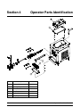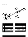
1
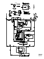
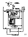
Model 390
Slush Freezer
Original Operating Instructions
048693-M
6/01 (Original Publication)
(Updated 7/17/12)
Complete this page for quick reference when service is required:
Taylor Distributor:
Address:
Phone:
Service:
Parts:
Date of Installation:
Information found on the data label:
Model Number:
Serial Number:
Electrical Specs:
Voltage
Cycle
Phase
Maximum Fuse Size:
A
Minimum Wire Ampacity:
A
E June, 2001 Taylor
All rights reserved.
048693--M
The word Taylor and the Crown design
are registered trademarks in the United States
of America and certain other countries.
Taylor Company
750 N. Blackhawk Blvd.
Rockton, IL 61072
Table of Contents
To the Installer . . . . . . . . . . . . . . . . . . . . . . . . . . . . . . . . . . . . . . .
1
Installer Safety . . . . . . . . . . . . . . . . . . . . . . . . . . . . . . . . . . . . . . . . . . . . . . . . . . .
1
Site Preparation . . . . . . . . . . . . . . . . . . . . . . . . . . . . . . . . . . . . . . . . . . . . . . . . . .
1
Water Connections (Water Cooled Units Only) . . . . . . . . . . . . . . . . . . . . . . .
2
Air Cooled Units . . . . . . . . . . . . . . . . . . . . . . . . . . . . . . . . . . . . . . . . . . . . . . . . . .
2
Electrical Connections . . . . . . . . . . . . . . . . . . . . . . . . . . . . . . . . . . . . . . . . . . . .
2
Refrigerant . . . . . . . . . . . . . . . . . . . . . . . . . . . . . . . . . . . . . . . . . . . . . . . . . . . . . .
3
Section 2
To the Operator . . . . . . . . . . . . . . . . . . . . . . . . . . . . . . . . . . . . . .
4
Section 3
Safety . . . . . . . . . . . . . . . . . . . . . . . . . . . . . . . . . . . . . . . . . . . . . . .
5
Section 4
Operator Parts Identification . . . . . . . . . . . . . . . . . . . . . . . . . .
7
Section 5
Important: To the Operator . . . . . . . . . . . . . . . . . . . . . . . . . . . .
9
Control Switch . . . . . . . . . . . . . . . . . . . . . . . . . . . . . . . . . . . . . . . . . . . . . . . . . . .
9
Indicator Light -- “Mix Low” . . . . . . . . . . . . . . . . . . . . . . . . . . . . . . . . . . . . . . . .
9
Indicator Light -- “Mix Out” . . . . . . . . . . . . . . . . . . . . . . . . . . . . . . . . . . . . . . . . .
9
Optional Feature: Remote Continuous Fill System . . . . . . . . . . . . . . . . . . . .
9
Operating Procedures . . . . . . . . . . . . . . . . . . . . . . . . . . . . . . . .
10
Assembly . . . . . . . . . . . . . . . . . . . . . . . . . . . . . . . . . . . . . . . . . . . . . . . . . . . . . . .
10
Sanitizing . . . . . . . . . . . . . . . . . . . . . . . . . . . . . . . . . . . . . . . . . . . . . . . . . . . . . . .
11
Priming . . . . . . . . . . . . . . . . . . . . . . . . . . . . . . . . . . . . . . . . . . . . . . . . . . . . . . . . .
11
Closing Procedures . . . . . . . . . . . . . . . . . . . . . . . . . . . . . . . . . . . . . . . . . . . . . .
12
Draining Product From The Freezing Cylinder . . . . . . . . . . . . . . . . . . . . . . .
12
Rinsing . . . . . . . . . . . . . . . . . . . . . . . . . . . . . . . . . . . . . . . . . . . . . . . . . . . . . . . . .
12
Cleaning . . . . . . . . . . . . . . . . . . . . . . . . . . . . . . . . . . . . . . . . . . . . . . . . . . . . . . . .
12
Disassembly . . . . . . . . . . . . . . . . . . . . . . . . . . . . . . . . . . . . . . . . . . . . . . . . . . . . .
13
Brush Cleaning . . . . . . . . . . . . . . . . . . . . . . . . . . . . . . . . . . . . . . . . . . . . . . . . . .
14
Section 1
Section 6
Table of Contents
Model 390
Table of Contents -- Page 2
Important: Operator Checklist . . . . . . . . . . . . . . . . . . . . . . . . .
15
During Cleaning And Sanitizing . . . . . . . . . . . . . . . . . . . . . . . . . . . . . . . . . . . .
15
Troubleshooting Guide . . . . . . . . . . . . . . . . . . . . . . . . . . . . . . . . . . . . . . . . . . . .
15
Regular Maintenance Checks . . . . . . . . . . . . . . . . . . . . . . . . . . . . . . . . . . . . . .
15
Winter Storage . . . . . . . . . . . . . . . . . . . . . . . . . . . . . . . . . . . . . . . . . . . . . . . . . . .
16
Section 8
Troubleshooting Guide . . . . . . . . . . . . . . . . . . . . . . . . . . . . . . .
17
Section 9
Parts Replacement Schedule . . . . . . . . . . . . . . . . . . . . . . . . . .
19
Section 10
Parts List . . . . . . . . . . . . . . . . . . . . . . . . . . . . . . . . . . . . . . . . . . . .
20
Wiring Diagrams . . . . . . . . . . . . . . . . . . . . . . . . . . . . . . . . . . . . . . . . . . . . . . . . .
28
Section 7
Note: Continuing research results in steady improvements; therefore, information
in this manual is subject to change without notice.
Note: Only instructions originating from the factory or its authorized translation
representative(s) are considered to be the original set of instructions.
E June, 2001 Taylor (Original Publication)
(Updated July, 2012)
All rights reserved.
048693--M
The word Taylor and the Crown design
are registered trademarks in the United States
of America and certain other countries.
Model 390
Taylor Company
750 N. Blackhawk Blvd.
Rockton, IL 61072
Table of Contents
Section 1
To the Installer
The following are general installation instructions. For
complete installation details, please see the check out
card.
This unit has many sharp edges that can
cause severe injuries.
Installer Safety
Site Preparation
In all areas of the world, equipment should be
installed in accordance with existing local codes.
Please contact your local authorities if you have any
questions.
Review the area the unit is to be installed in before
uncrating the unit, making sure that all possible
hazards the user or equipment may come into have
been addressed.
Care should be taken to ensure that all basic safety
practices are followed during the installation and
servicing activities related to the installation and
service of Taylor equipment.
S
S
S
S
For Indoor Use Only: This unit is designed to operate
indoors, under normal ambient temperatures of
70_-75_F (21_-24_C). The freezer has successfully
performed in high ambient temperatures of
104_(40_C) at reduced capacities.
Only authorized Taylor service personnel
should perform installation and repairs on
the equipment.
Authorized service personnel should consult
OSHA Standard 29CFRI910.147 or the
applicable code of the local area for the
industry standards on lockout/tagout
procedures before beginning any installation
or repairs.
Authorized service personnel must ensure
that the proper PPE is available and worn
when required during installation and
service.
Authorized service personnel must remove
all metal jewelry, rings, and watches before
working on electrical equipment.
This unit must NOT be installed in an area
where a water jet or hose can be used. NEVER use a
water jet or hose to rinse or clean the unit. Failure to
follow this instruction may result in electrocution.
This unit must be installed on a level surface
to avoid the hazard of tipping. Extreme care should be
taken in moving this equipment for any reason. Two or
more persons are required to safely move this unit.
Failure to comply may result in personal injury or
equipment damage.
The main power supply(s) to the machine
must be disconnected prior to performing any repairs.
Failure to follow this instruction may result in personal
injury or death from electrical shock or hazardous
moving parts as well as poor performance or damage
to the equipment.
Uncrate the unit and inspect it for damage. Report any
damage to your Taylor Distributor.
This piece of equipment is made in the USA and has
USA sizes of hardware. All metric conversions are
approximate and vary in size.
Note: All repairs must be performed by an
authorized Taylor Service Technician.
090901
Model 390
1
To the Installer
Water Connections
(Water Cooled Units Only)
Electrical Connections
Each freezer requires one power supply. Check the
data label on the freezer for branch circuit overcurrent
protection or fuse, circuit ampacity and electrical
specifications. Refer to the wiring diagram provided
inside of the electrical box, for proper power
connections.
An adequate cold water supply must be provided with
a hand shut--off valve. On the underside of the base
pan, two 3/8” I.P.S. (for single--head units) or two 1/2”
I.P.S. (for double--head units) water connections for
inlet and outlet have been provided for easy hook--up.
1/2” inside diameter water lines should be connected
to the machine. (Flexible lines are recommended, if
local codes permit.) Depending on local water
conditions, it may be advisable to install a water
strainer to prevent foreign substances from clogging
the automatic water valve. There will be only one water
“in” and one water “out” connection. DO NOT install a
hand shut--off valve on the water “out” line! Water
should always flow in this order: first through the
automatic water valve; second, through the
condenser; and third, through the outlet fitting to an
open trap drain.
In the United States, this equipment is intended to be
installed in accordance with the National Electrical
Code (NEC), ANSI/NFPA 70--1987. The purpose of
the NEC code is the practical safeguarding of persons
and property from hazards arising from the use of
electricity. This code contains provisions considered
necessary for safety. Compliance therewith and
proper maintenance will result in an installation
essentially free from hazard!
In all other areas of the world, equipment should be
installed in accordance with the existing local codes.
Please contact your local authorities.
FOLLOW YOUR LOCAL ELECTRICAL CODES!
A back flow prevention device is required
on the incoming water connection side. Please
refer to the applicable National, State, and local codes
for determining the proper configuration.
Air Cooled Units
CAUTION: THIS EQUIPMENT MUST BE
PROPERLY GROUNDED! FAILURE TO DO SO
CAN RESULT IN SEVERE PERSONAL INJURY
FROM ELECTRICAL SHOCK!
Air cooled units require a minimum of 6” (152 mm) of
clearance around both sides and 0” at the rear of the
freezer. This is required to allow for adequate air flow
across the condenser(s). Failure to allow adequate
clearance can reduce the refrigeration capacity of the
freezer and possibly cause permanent damage to the
compressor(s).
This unit is provided with an equipotential
grounding lug that is to be properly attached to the rear
of the frame by the authorized installer. The installation
location is marked by the equipotential bonding
symbol (5021 of IEC 60417-1) on both the removable
panel and the equipment’s frame.
110328
To the Installer
2
Model 390
Refrigerant
S
S
S
Stationary appliances which are not
equipped with a power cord and a plug or
another device to disconnect the appliance
from the power source must have an all-pole
disconnecting device with a contact gap of
at least 3 mm installed in the external
installation.
Appliances that are permanently connected
to fixed wiring and for which leakage
currents may exceed 10 mA, particularly
when disconnected, not used for long
periods, or during initial installation, shall
have protective devices such as a GFI to
protect against the leakage of current,
installed by authorized personnel to the local
codes.
Supply cords used with this unit shall be
oil-resistant, sheathed flexible cable, not
lighter than ordinary polychloroprene or
other equivalent synthetic
elastomer-sheathed cord (Code designation
60245 IEC 57) installed with the proper cord
anchorage to relieve conductors from strain,
including twisting, at the terminals and
protect the insulation of the conductors from
abrasion.
In consideration of our environment, Taylor
proudly uses only earth friendly HFC refrigerants. The
HFC refrigerant used in this unit is R404A. This
refrigerant is generally considered non-toxic and
non-flammable, with an Ozone Depleting Potential
(ODP) of zero (0).
However, any gas under pressure is potentially
hazardous and must be handled with caution. NEVER
fill any refrigerant cylinder completely with liquid.
Filling the cylinder to approximately 80% will allow for
normal expansion.
Use only R134a refrigerant that conforms to
the AHI standard 700 specification. The use of any
other refrigerant may expose users and operators to
unexpected safety hazards.
Refrigerant liquid sprayed onto the skin may
cause serious damage to tissue. Keep eyes and skin
protected. If refrigerant burns should occur, flush
immediately with cold water. If burns are severe, apply
ice packs and contact a physician immediately.
Beater rotation must be clockwise as viewed
looking into the freezing cylinder of the freezer.
Taylor reminds technicians to be cautious of
government laws regarding refrigerant recovery,
recycling, and reclaiming systems. If you have any
questions regarding these laws, please contact the
factory Service Department.
Note: The following procedures should be
performed by a trained service technician.
To correct the rotation on a three--phase unit,
interchange any two incoming power supply lines at
the freezer main terminal block only. To correct rotation
on a single--phase unit, change the leads inside the
beater motor. (Follow diagram printed on motor.)
WARNING: R404A refrigerant used in
conjunction with polyolester oils is extremely moisture
absorbent. When opening a refrigeration system, the
maximum time the system is open must not exceed 15
minutes. Cap all open tubing to prevent humid air or
water from being absorbed by the oil.
Electrical connections are made directly to the
terminal block. The terminal block is located in the
control box located behind the left side panel.
120717
Model 390
3
To the Installer
Section 2
To the Operator
The freezer you have purchased has been carefully
engineered and manufactured to give you dependable
operation. The Taylor Model 390, when properly
operated and cared for, will produce a consistent
quality product. Like all mechanical products, it will
require cleaning and maintenance. A minimum
amount of care and attention is necessary if the
operating procedures outlined in this manual are
followed closely.
For additional information regarding applicable local
laws, please contact the municipal facility and/or local
distributor.
Compressor Warranty Disclaimer
This Operator’s Manual should be read before
operating or performing any maintenance on your
equipment.
The refrigeration compressor(s) on this machine are
warranted for the term indicated on the warranty card
accompanying this machine. However, due to the
Montreal Protocol and the U.S. Clean Air Act
Amendments of 1990, many new refrigerants are
being tested and developed, thus seeking their way
into the service industry. Some of these new
refrigerants are being advertised as drop--in
replacements for numerous applications. It should be
noted that, in the event of ordinary service to this
machine’s refrigeration system, only the refrigerant
specified on the affixed data label should be used.
The unauthorized use of alternate refrigerants will void
your compressor warranty. It will be the owner’s
responsibility to make this fact known to any technician
he employs.
The Model 390 will NOT eventually compensate and
correct for any errors during the set--up or filling
operations. Thus, the initial assembly and priming
procedures are of extreme importance. It is strongly
recommended that personnel responsible for the
equipment’s operation, both assembly and
disassembly, sit down together and go through these
procedures in order to be properly trained and to make
sure that no misunderstandings exist.
In the event you should require technical assistance,
please contact your local authorized Taylor Distributor.
Note: Warranty is valid only if the parts are authorized
Taylor parts, purchased from an authorized Taylor
Distributor, and the required service work is provided
by an authorized Taylor service technician. Taylor
reserves the right to deny warranty claims on
equipment or parts if non--approved parts or
refrigerant were installed in the machine, system
modifications were performed beyond factory
recommendations, or it is determined that the failure
was caused by neglect or abuse.
It should also be noted that Taylor does not warrant the
refrigerant used in its equipment. For example, if the
refrigerant is lost during the course of ordinary service
to this machine, Taylor has no obligation to either
supply or provide its replacement either at billable or
unbillable terms. Taylor does have the obligation to
recommend a suitable replacement if the original
refrigerant is banned, obsoleted, or no longer available
during the five year warranty of the compressor.
If the crossed out wheeled bin symbol is
affixed to this product, it signifies that this product is
compliant with the EU Directive as well as other similar
legislation in effect after August 13, 2005. Therefore,
it must be collected separately after its use is
completed, and cannot be disposed as unsorted
municipal waste.
Taylor will continue to monitor the industry and test
new alternates as they are being developed. Should a
new alternate prove, through our testing, that it would
be accepted as a drop--in replacement, then the above
disclaimer would become null and void. To find out the
current status of an alternate refrigerant as it relates to
your compressor warranty, call the local Taylor
Distributor or the Taylor Factory. Be prepared to
provide the Model/Serial Number of the unit in
question.
The user is responsible for returning the product to the
appropriate collection facility, as specified by your local
code.
090901
To the Operator
4
Model 390
Section 3
Safety
We at Taylor are concerned about the safety of the
operator when he or she comes in contact with the
freezer and its parts. Taylor has gone to extreme
efforts to design and manufacture built--in safety
features to protect both you and the service technician.
As an example, warning labels have been attached to
the freezer to further point out safety precautions to the
operator.
IMPORTANT -- Failure to adhere to the
following safety precautions may result in severe
personal injury. Failure to comply with these
warnings may damage the machine and its
components. Component damage will result in
part replacement expense and service repair
expense.
S
DO NOT operate the freezer unless it is
properly grounded.
S
DO NOT operate the freezer with larger
fuses than specified on the freezer data
label.
S
All repairs must be performed by an
authorized Taylor service technician. The
main power supplies to the machine must
be disconnected prior to performing any
repairs.
S
Cord Connected Units: Only Taylor
authorized service technicians may install a
plug on this unit.
S
Stationary appliances which are not
equipped with a power cord and a plug or
another device to disconnect the appliance
from the power source must have an all-pole
disconnecting device with a contact gap of
at least 3mm installed in the external
installation.
S
Appliances that are permanently connected
to fixed wiring and for which leakage
currents may exceed 10 mA, particularly
when disconnected, not used for long
periods, or during initial installation, shall
have protective devices such as a GFI to
protect against the leakage of current,
installed by authorized personnel to the local
codes.
S
Supply cords used with this unit shall be
oil-resistant, sheathed flexible cable, not
lighter than ordinary polychloroprene or
other equivalent synthetic
elastomer-sheathed cord (Code designation
60245 IEC 57) installed with the proper cord
anchorage to relieve conductors from strain,
including twisting, at the terminals and
protect the insulation of the conductors from
abrasion.
To Operate Safely:
DO NOT operate the freezer without reading
this Operator Manual. Failure to follow this instruction
may result in equipment damage, poor freezer
performance, health hazards, or personal injury.
Per IEC 60335--1 and its part 2 standards, “This
appliance is to be used only by trained personnel. It is
not intended for use by children or people with reduced
physical, sensory, or mental capabilities, or lack of
experience and knowledge, unless given supervision
or instruction concerning the use of the appliance by
a person responsible for their safety.”
This unit is provided with an equipotential
grounding lug that is to be properly attached to the rear
of the frame by the authorized installer. The installation
location is marked by the equipotential bonding
symbol (5021 of IEC 60417-1) on both the removable
panel and the equipment’s frame.
DO NOT use a water jet to clean or rinse the
freezer. Failure to follow these instructions may result
in serious electrical shock.
Failure to follow these instructions may result in
electrocution. Contact your local authorized Taylor
Distributor for service.
110328
Model 390
5
Safety
This freezer must be placed on a level
surface. Failure to comply may result in personal injury
or equipment damage.
DO NOT allow untrained personnel to
operate this machine.
S DO NOT operate the freezer unless all
service panels and access doors are
restrained with screws.
S DO NOT remove any internal operating
parts (examples: freezer door, beater,
scraper blades, etc.) unless all control
switches are in the OFF position.
Failure to follow these instructions may result in severe
personal injury to fingers or hands from hazardous
moving parts.
S
Cleaning and sanitizing schedules are
governed by your state or local regulatory agencies
and must be followed accordingly. Please refer to the
cleaning section of this manual for the proper
procedure to clean this unit.
DO NOT obstruct air intake and discharge openings:
6” (152 mm) minimum air space on both sides, and 0”
at the rear of the freezer. Failure to follow this
instruction may cause poor freezer performance and
damage to the machine.
This unit has many sharp edges that can
cause severe injuries.
S
S
For Indoor Use Only: This unit is designed to operate
indoors, under normal ambient temperatures of 70_ 75_F (21_ - 24_C). The freezer has successfully
performed in high ambient temperatures of 104_F
(40_C) at reduced capacities.
DO NOT put objects or fingers in the door
spout. This may contaminate the product
and cause severe personal injury from blade
contact.
USE EXTREME CAUTION when removing
the beater asssembly. The scraper blades
are very sharp.
NOISE LEVEL: Airborne noise emission does not
exceed 78 dB(A) when measured at a distance of 1.0
meter from the surface of the machine and at a height
of 1.6 meters from the floor.
090901
Safety
6
Model 390
Section 4
Item
Description
Operator Parts Identification
Part Number
1
Hopper Cover
X38458
2
Gasket--Hopper Cover
038375
3
Feed Tube
015176--9
4
Drip Pan
035034
5
Splash Shield
046177
6
Drip Tray
046275
Model 390
7
Operator Parts Identification
Beater Assembly
Item
Description
Part Number
Item
Description
Part Number
1
Freezer Door
X47982
11
Beater Shaft
036412
2
Gasket--Door
014030
12
Seal--Beater Shaft
032560
3
Front Bearing
013116
13
O--Ring--Beater Shaft
025307
4
O--Ring--Baffle
018550
14
Valve Handle Pin
X25929
5
Baffle Arm
047729
15
Draw Valve
047734
6
Baffle
X47731
16
Ice Buster
047735
7
Guide Bearing
014496
17
Draw Handle
X47384
8
Beater
X46233
18
O--Ring--Draw Valve (2)
032504
9
Scraper Blade
046237
19
Stud Nut
029880
10
Clip--Scraper Blade
046238
Operator Parts Identification
8
Model 390
Section 5
Important: To the Operator
Control Switch
Optional Feature:
Remote Continuous Fill System
The center position is “OFF”. The “WASH” position
activates the beater motor only. The “AUTO” position
allows the beater motor and compressor to run.
If your Model 390 Taylor Freezer has been factory
equipped with a Remote Continuous Fill System, the
mix supply to the freezer will be replenished
automatically from mix tanks located in a remote
location.
When the “Mix Out” indicator lights, the mix supply in
the freezer hopper will be replenished automatically.
Indicator Light -- “Mix Low”
To start the unit after cleaning:
Located on the front of the machine is a mix level
indicating light. When the light is flashing, it indicates
that the mix hopper has a low supply of product and
should be refilled as soon as possible. Neglecting to
add mix when the light comes on will cause the
machine to sway and may eventually cause damage
to the beater assembly and freezer door.
Indicator Light -- “Mix Out”
Also located on the front of the machine is a mix out
indicating light. When the light is flashing, it indicates
that the hopper is empty and the mix supply needs
replenishing. To prevent damage to the unit,
refrigeration discontinues automatically when the mix
out indicator lights.
1.
Place the power switch in the “Wash” position.
2.
Press the “Fill” button, located under the control
channel, until the freezing cylinder is at least
half full.
Note: Do not remove the hopper cover while
the unit is filling with mix, as some splashing
may occur.
3.
Once the freezing cylinder is at least half full,
place the power switch in the “Auto” mode and
the hopper will be filled automatically, and the
fill system will discontinue.
4.
Place the mix feed tube into the mix inlet.
5.
Raise the draw switch arm to initiate
refrigeration. When the refrigeration stops, the
product is ready to serve.
Recommended Pressure: 12 -- 15 PSI (83 -- 103 kPa)
IMPORTANT: Do not exceed 15 PSI or excessive
splashing will occur.
080714
Model 390
9
Important: To the Operator
Section 6
Operating Procedures
Following are step--by--step operating procedures for
the model 390 slush freezer. This unit has a 20 quart
(18.9 liter) mix hopper and the freezing cylinder holds
7 quarts (6.6 liters) of slush product.
Step 2
Before installing the beater assembly, check the
scraper blades for any nicks or signs of wear. If any
nicks are present or if the blade is worn, replace both
blades. If blades are in good condition, install the
scraper blade clip over the scraper blade. Place the
rear scraper blade over the rear holding pin (knife edge
to the outside). Holding the blade on the beater, turn
it over and install the front blade the same way.
We begin our instructions at the point where we enter
the store in the morning and finds the parts
disassembled and laid out to air dry from the previous
night’s brush cleaning.
Holding the blades in position, insert the beater
assembly into the freezing cylinder and slide into
position over the drive shaft. Turn the beater slightly to
be certain that the beater is properly seated. When in
position, the beater will not protrude beyond the front
of the freezing cylinder.
These opening procedures will show you how to
assemble these parts into the freezer, sanitize them
and prime the freezer with the slush base you have
selected in preparation to serve your first portion.
If you are disassembling the machine for the first time
or need information to get to this starting point in our
instructions, turn to ”Disassembly” on page 13, and
start there.
Step 3
Install the baffle assembly. Lubricate the o--ring, and
install it on the front end of the baffle assembly. Install
the guide bearing on the rear end of the baffle
assembly.
Install the bearing end of the baffle assembly into the
pilot hole in the drive shaft.
Assembly
Step 4
Assemble the freezer door with the “Ice Buster” (door
spout clearing device). To assemble the door with the
ice buster, install the o--rings on the draw valve and
lubricate. (See illustrations on page 13.)
BE SURE THE CONTROL SWITCH IS IN
THE “OFF” POSITION. Failure to do so may cause
injury from electrocution or hazardous moving parts.
Insert the draw valve into the door, leaving
approximately 1/2” of the valve sticking out the top of
the door.
Note: When lubricating parts, use an approved food
grade lubricant (example: Taylor Lube).
Rotate the draw valve so the flats on the top of the draw
valve are perpendicular to the door face (see
illustration).
Step 1
Install beater drive shaft. Slide the o--ring into the first
groove on the drive shaft. Lubricate the groove, o--ring,
and shaft portion that comes in contact with the
bearing on the beater drive shaft. DO NOT lubricate
the hex end of the drive shaft. Slide the seal over the
shaft and groove until it snaps into place. Fill the inside
portion of the seal with 1/4” more lubricant and evenly
lubricate the flat side of the seal that fits onto the rear
shell bearing.
Insert the ice buster through the door spout and into
the slot located just above the lower o--ring.
With the ice buster in place, rotate the draw valve to
allow installation of the draw handle. This will lock the
ice buster in place. Install the draw handle pin, and
close the draw valve by moving the handle to the left.
Place the large rubber gasket into the groove on the
back side of the freezer door.
Install the drive shaft into the freezing cylinder, hex end
first, and into the rear shell bearing until the seal fits
securely over the rear shell bearing. Be certain the
drive shaft fits into the drive coupling without binding.
Operating Procedures
Slide the white plastic front bearing onto the bearing
hub making certain that the flanged end of the bearing
is resting against the freezer door. Do not lubricate the
door gasket or front bearing.
10
Model 390
Step 5
Install the freezer door. Place the front end of the baffle
into the hole in the center of the door. Position the door
onto the four studs on the front of the freezing cylinder
and push the door into place. Install the four
handscrews onto the studs and tighten them equally in
a criss--cross pattern to insure the door is snug. DO
NOT over--tighten the handscrews.
Step 4
Place the control switch in the “WASH” position. This
will cause the sanitizing solution in the freezing
cylinder to be agitated. Allow the solution to agitate for
five minutes.
Note: If the freezer door does not go into place easily,
position open end of beater assembly in the 11 o’clock
position.
Step 5
Place an empty mix pail beneath the door spout and
move the draw handle to the right. Draw off all the
sanitizing solution. When the sanitizer stops flowing
from the door spout, move the draw handle to the left
and place the control switch in the “OFF” position.
Step 6
Rotate the baffle assembly so the hole in the end of the
shaft is vertical. Insert the baffle arm between the draw
valve spout supports and into the hole in the baffle
assembly.
Step 6
With sanitized hands, assemble the hopper gasket
around the top edge of the mix hopper. Stand the feed
tube in the corner of the hopper.
Note: During operation, the baffle arm rests on the
spout support.
Step 7
Install the rear drip pan. Slide the long drip pan into the
hole in the front panel.
Priming
Step 8
Install the front drip tray and the splash shield under
the door spout.
Note: If your freezer is equipped with the Remote
Continuous Fill System, replace the following Priming
instructions with the information on page 9.
Step 9
Lay the hopper gasket and feed tube in the bottom of
the mix hopper.
Step 1
With a mix pail beneath the door spout, move the draw
handle to the right. Fill the hopper with FRESH slush
product and allow it to flow into the freezing cylinder.
This will force out any remaining sanitizing solution.
When full strength mix is flowing from the door spout,
move the draw handle to the left.
Sanitizing
Step 1
Prepare an approved 100 PPM sanitizing solution
(examples: 2--1/2 gal. [9.5 liters] of Kay--5R or 2
gal. [7.6 liters] of Stera--SheenR). USE WARM
WATER AND FOLLOW THE MANUFACTURER’S
SPECIFICATIONS.
Step 2
When the slush product has stopped bubbling down
into the freezing cylinder, install the feed tube in the mix
inlet hole.
Step 3
Place the control switch in the “AUTO” position. To
begin refrigeration, raise the rod resting on top of the
valve handle pin. When the unit cycles off, the product
will be at serving viscosity.
Step 2
Pour the sanitizing solution into the hopper and allow
it to flow into the freezing cylinder.
Step 3
While the solution is flowing into the freezing cylinder,
brush clean the mix hopper, mix inlet hole, feed tube
and mix level sensing probes.
Step 4
Place the hopper cover into position.
080714
Model 390
11
Operating Procedures
Closing Procedures
Rinsing
To disassemble the model 390, the following items will
be needed:
Step 1
Pour two gallons (7.6 liters) of cool, clean water into
the mix hopper. With the brushes provided, scrub the
mix hopper, mix inlet hole and mix level sensing
probes.
S
S
S
S
S
Two cleaning pails
Sanitized stainless steel rerun can with lid
Necessary brushes (provided with freezer)
Cleaner
Single service towels
Step 2
With a mix pail beneath the door spout, place the
control switch in the “WASH” position and move the
draw handle to the right. Drain all the rinse water from
the freezing cylinder. When the rinse water stops
flowing from the door spout, move the draw handle to
the left and place the control switch in the “OFF”
position.
Draining Product From The
Freezing Cylinder
Repeat this procedure until the rinse water being
drawn from the freezing cylinder is clear.
Step 1
Place the control switch in the “OFF” position as far
ahead of cleaning time as possible. This will allow
frozen product to soften for easier cleaning.
Cleaning
Step 2
Remove the hopper cover, gasket, and feed tube. Take
these parts to the sink for cleaning.
Step 1
Prepare an approved 100 PPM cleaning solution
(examples: 2--1/2 gal. [9.5 liters] of Kay--5R or 2
gal. [7.6 liters] of Stera--SheenR). USE WARM
WATER AND FOLLOW THE MANUFACTURER’S
SPECIFICATIONS.
Step 3
If local health codes permit the use of rerun, place
a sanitized, NSF approved stainless steel rerun
container beneath the door spout. Place the control
switch in the “WASH” position and move the draw
handle to the right. When all the product stops flowing
from the door spout, move the draw handle to the left
and place the control switch in the “OFF” position.
Place a sanitized lid on the rerun container and place
it in the walk--in cooler.
(Note: For additional information regarding the proper
use of rerun, see item 7 on page 15.)
Step 2
Pour the cleaning solution into the hopper and allow it
to flow into the freezing cylinder.
Step 3
While the solution is flowing into the freezing cylinder,
brush clean the mix hopper, mix inlet hole, and mix
level sensing probes.
Step 4
Place the control switch in the “WASH” position. This
will cause the cleaning solution to be agitated.
Note: If local health codes DO NOT permit the use
of rerun, the product must be discarded. Follow the
instructions in the previous step, except drain the
product into a mix pail and properly discard the mix.
Step 5
Place an empty mix pail beneath the door spout and
move the draw handle to the right. Draw off all of the
cleaning solution. When the solution stops flowing
from the door spout, move the draw handle to the left
and place the control switch in the “OFF” position.
ALWAYS FOLLOW LOCAL HEALTH CODES.
090901
Operating Procedures
12
Model 390
Disassembly
Step 2
Remove the front drip tray and splash shield and take
them to the sink for cleaning.
BE SURE THE CONTROL SWITCH IS IN
THE “OFF” POSITION. Failure to do so may cause
injury from electrocution or hazardous moving parts.
Step 1
Remove the handscrews, freezer door, baffle
assembly, beater assembly, scraper blades, and drive
shaft from the freezing cylinder. Take these parts to the
sink for cleaning.
Model 390
13
Operating Procedures
Brush Cleaning
Step 3
Remove the draw valve handle and pin, ice buster,
draw valve, front bearing and gasket from the freezer
door. Remove the scraper blade clips from the scraper
blades. Remove the two o--rings from the draw valve,
and the o--ring and guide bearing from the baffle
assembly.
Step 1
Prepare a sink with an approved cleaning solution
(examples: Kay--5R or Stera--SheenR). USE WARM
WATER AND FOLLOW THE MANUFACTURER’S
SPECIFICATIONS. (If another approved cleaner is
used, dilute according to label instructions.)
Step 4
Return to the freezer with a small amount of cleaning
solution. Brush clean the rear shell bearing at the back
of the freezing cylinder with the black bristle brush.
IMPORTANT: Follow label directions, as too
STRONG of a solution can cause parts damage, while
too MILD of a solution will not provide adequate
cleaning.) Make sure all brushes provided with the
freezer are available for brush cleaning.
Step 5
Remove the rear drip pan.
Step 2
Remove the o--ring and seal from the drive shaft.
Note: If the drip pan is filled with an excessive amount
of mix, it is an indication that the drive shaft o--ring, seal
or both should be replaced or properly lubricated.
Note: To remove o--rings, use a single service towel
to grasp the o--ring. Apply pressure in an upward
direction until the o--ring pops out of its groove. With
the other hand, push the top of the o--ring forward and
it will roll out of the groove and can be easily removed.
If there is more than one o--ring to be removed, always
remove the rear o--ring first. This will allow the o--ring
to slide over the forward rings without falling into the
open grooves.
Operating Procedures
Step 6
Thoroughly brush clean all disassembled parts in the
cleaning solution making sure all lubricant and mix film
is removed. Place all the cleaned parts on a clean, dry
surface to air dry.
Step 7
Wipe clean all exterior surfaces of the freezer.
14
Model 390
Section 7
Important: Operator Checklist
During Cleaning And Sanitizing
j 7. IF LOCAL HEALTH CODES PERMIT THE
USE OF RERUN, make sure the rerun is stored
in a sanitized, covered stainless steel container
and used the following day. Discard all rerun
once a week.
ALWAYS FOLLOW LOCAL HEALTH CODES.
Cleaning and sanitizing schedules are governed
by federal, state, or local regulatory agencies,
and must be followed accordingly. If the unit
has a “Standby mode”, it must not be used in
lieu of proper cleaning and sanitizing
procedures and frequencies set forth by the
ruling health authority. The following check
points should be stressed during the cleaning
and sanitizing operations.
Regular Maintenance Checks
j 1. Rotate scraper blades to allow both sides of the
knife edge to wear evenly. This will contribute to
self--sharpening and help maintain fast efficient
freezing.
j 2. Replace scraper blades that are nicked or
damaged.
CLEANING AND SANITIZING MUST BE
PERFORMED DAILY.
j 3. Before installing the beater, be certain that
scraper blades are properly attached over the
beater pins.
Troubleshooting Guide
j 4. Dispose of o--rings or seals that are worn, torn
or fit too loosely and replace with new ones.
j 1. Thoroughly clean and sanitize the machine
regularly, including complete disassembly and
brush cleaning.
j 5. Follow all lubrication procedures as outlined in
the “Assembly” instructions of this manual.
j 2. Use all brushes supplied for thorough cleaning.
The brushes are specially designed to reach all
mix passageways.
j 6. Check rear shell bearing for signs of wear
(excessive mix leakage in rear drip pan) and be
certain it is properly cleaned.
j 3. Use the white bristle brush to clean the mix inlet
hole which extends from the mix hopper down
to the rear of the freezing cylinder.
j 7. Check the condenser for accumulation of dirt
and lint. Dirty condensers will reduce the
efficiency and capacity of the machine.
Condensers should be cleaned monthly with a
soft brush. Never use screwdrivers or other
metal probes to clean between the fins.
Note: For machines equipped with an air filter,
it will be necessary to vacuum clean the filters
on a monthly schedule.
j 4. Use the black bristle brush to thoroughly clean
the rear shell bearing at the rear of the freezing
cylinder. Be sure to have a generous amount of
cleaning solution on the brush.
j 5. Properly prepare the cleaning and sanitizing
solutions. Read and follow label directions
carefully. Too strong of a solution may damage
the parts and too weak of a solution will not do
an adequate job of cleaning or sanitizing.
j 8. If your machine is water cooled, check the water
lines for kinks or leaks. Kinks can occur when
the machine is moved back and forth for
cleaning
or
maintenance
purposes.
Deteriorated or cracked water lines should be
replaced only by an authorized Taylor
mechanic.
j 6. Using a screwdriver and cloth towel, keep the
female hex drive socket and rear shell bearing
clean and free of lubricant and mix deposits.
090901
Model 390
15
Operating Procedures
Winter Storage
If the place of business is to be closed during the winter
months, it is important to protect the freezer by
following certain precautions, particularly if the
building is to be left unheated and subject to freezing
conditions.
Wrap detachable parts of the freezer such as beater
and blades, drive shaft, baffle and freezer door, and
place in a protected dry place. Rubber trim parts and
gaskets can be protected by wrapping with
moisture--proof paper. All parts should be thoroughly
cleaned of dried mix or lubrication accumulations
which attract mice and other vermin.
Disconnect the freezer from the main power source to
prevent possible electrical damage.
On water cooled freezers, disconnect the water
supply. Relieve pressure on spring in water valve. Use
air pressure on the outlet side to blow out any
remaining water in the condenser. This is extremely
important. Failure to follow this procedure may cause
severe and costly damage to the refrigeration system.
Your local Taylor Distributor can perform this service
for you.
080324
Operating Procedures
16
Model 390
Section 8
PROBLEM
1. No product being
dispensed with draw valve
opened.
2. Product too thin.
3. Product too stiff.
4. Scored walls of freezing
cylinder.
5. Unable to remove drive
shaft.
6. Excessive mix leakage in
rear drip pan.
Model 390
Troubleshooting Guide
PROBABLE CAUSE
REMEDY
PAGE
REF.
a. Improper mixing of
product.
a. Carefully follow directions
for mixing product.
----
b. Mix low condition.
b. Add mix to mix hopper.
a. Improper mixing of
product.
a. Carefully follow directions
for mixing product.
----
b. Missing, incorrectly
installed or bad scraper
blades.
b. Replace or install correctly.
10
c. Consistency control needs
adjusting.
c. Contact a service
technician.
----
a. Consistency control knob
needs adjusting.
a. Contact a service
technician.
----
b. Improper mixing of
product.
b. Carefully follow directions
for mixing product.
----
c. Insufficient product in the
freezing cylinder.
c. Keep hopper full of mix.
9
a. Broken beater pins.
a. Repair or replace beater
assembly.
----
b. Gear unit out of alignment.
b. Contact a service
technician.
----
c. Bent beater assembly.
c. Repair or replace.
----
d. Missing front bearing.
d. Replace or install front
bearing.
10
a. Lubrication on hex end of
drive shaft.
a. Do not lubricate the hex
end. Contact service
technician for removal.
10
b. Rounded corners of the
drive shaft, drive coupling
or both.
b. Replace drive shaft, drive
coupling or both.
----
a. Improper or inadequate
lubrication on drive shaft
o--ring or seal on drive
shaft.
a. Use an approved food
grade lubricant (example:
Taylor Lube) and follow
lubrication procedures.
10
b. Bad or missing o--ring or
seal on drive shaft.
b. Replace rubber parts every
3 months.
19
c. Worn rear shell bearing.
c. Contact a service
technician for replacement.
----
17
9
Operating Procedures
PROBLEM
7. No freezer operation with
unit in the “AUTO” position.
8. Unit not freezing product
when in the “AUTO”
position.
9. Missing guide bearing.
10. Excessive leakage from
the door spout.
11. Door will not go into
position easily.
Operating Procedures
PROBABLE CAUSE
REMEDY
PAGE
REF.
a. Unit unplugged.
a. Plug cord in wall
receptacle.
----
b. Beater motor has tripped
the internal overload.
b. Place control switch in the
“OFF” position. Allow the
motor to cool, then resume
normal operation. Contact
a service technician if
problem continues.
----
c. Tripped circuit breaker or
blown fuse.
d. The rod resting on top of
the valve handle pin must
be raised to activate
refrigeration.
c. Reset circuit breaker or
replace blown fuse.
d. Raise and release the
lever.
----
a. Refrigerant leak.
a. Call for service to repair
leak.
----
b. Dirty condensers.
b. Clean regularly.
15
a. Guide bearing stuck in
drive shaft.
a. Remove guide bearing
from hole in drive shaft.
----
a. Improper or inadequate
lubrication on draw valve
o--rings.
a. Use an approved food
grade lubricant (example:
Taylor Lube) and follow
lubrication procedures.
10
b. Bad or missing o--rings on
draw valve.
b. Replace rubber parts every
three months.
19
a. Position of beater
assembly.
a. The open end of the beater
assembly should be in the
11 o’clock position.
11
18
11
Model 390
Section 9
PART
DESCRIPTION
Parts Replacement Schedule
EVERY
3 MONTHS
Drive Shaft O--ring
X
Drive Shaft Seal
X
Scraper Blade
Inspect & Replace
if Necessary
Baffle O--ring
X
Guide Bearing
X
Freezer Door Gasket
X
Front Bearing
X
Draw Valve O--ring
X
EVERY
6 MONTHS
ANNUALLY
Minimum
Black Bristle Brush, 1” x 2”
Inspect & Replace
if Necessary
Minimum
Double Ended Brush
Inspect & Replace
if Necessary
Minimum
White Bristle Brush, 1” x 2”
Inspect & Replace
if Necessary
Minimum
White Bristle Brush, 3” x 7”
Inspect & Replace
if Necessary
Minimum
Refer to Parts List on the next page when ordering above parts.
Model 390
19
Operating Procedures
Parts List
20
+CAPACITOR-RUN
ARM-BAFFLE *390*
BAFFLE ASSEMBLY
+O-RING-.291 ID X .080W
BEARING-FRONT
BEARING-GUIDE
BEARING-REAR SHELL *PLASTIC*
+WASHER-BEARING LOCK
+O-RING-1-1/16 OD X .070 WALL
+NUT-BRASS BEARING
+GUIDE-DRIP SEAL
BEARING-UNIT-REAR 1 PULLEY
BEATER A.-7QT-1 PIN-SUPPORT
+BLADE-SCRAPER-PLASTIC 9-13/16L
+CLIP-SCRAPER BLADE
BELT-POLY V-525J10
BLOCK-TERMINAL 2P
BRUSH-DOUBLE ENDED-PUMP&FEED T
BRUSH-DRAW VALVE 1"ODX2"X17"L
BRUSH-MIX PUMP BODY-3"X7"WHITE
BRUSH-REAR BRG 1IN.DX2IN.LGX14
BUSHING-SNAP 11/16 ID X 7/8 OD
COMPRESSOR L63B562BBCB
+CAPACITOR-RUN 30UF/370V
+CAPACITOR-START 161-193UF
+RELAY-START-COMPRESSOR
+GROMMET-COMPRESSOR MOUNT
+SLEEVE-MOUNTING-COMP.
COMPRESSOR L63B562DBLB
COMPRESSOR-RS80C1E-CAV
DESCRIPTION
1
1
2
2
1
1
1
1
1
1
1
1
1
1
1
4
4
1
1
X46233
046237
046238
047728
039422
013072
013073
023316
013071
010548
048727-27E
038487
031790
047067
037428
039924
048727-33E
051958-27
012906
1
1
1
1
1
1
1
1
1
1
QTY.
047729
X47731
018550
013116
014496
032511
012864
018432
028991
028992
PART
NUMBER
103
103
000
103
000
103
000
000
000
000
000
512
103
103
103
000
000
512
512
103
103
000
000
000
000
000
000
000
000
WARR.
CLASS
S/N K6051964 & UP - BRISTOL - 208-230V 60HZ 3PH
S/N J8086700 - K6036687 - COPELAND - 208-230V
60HZ 1PH
S/N K6051964 & UP - BRISTOL - 208-230V 60HZ 1PH
USE - KIT A.-REAR BEARING UNIT
REMARKS
PARTS
UPDATE
Copeland Compressor - J8086700/Up (Update 134)
Section 10
Parts List
100701
+ Available Separately
Model 390
+ Available Separately
Model 390
21
Parts List
033044-1
051957-27
051958-33
047065047070
047069
047067
048343-33
046558
X48316
046866
039397
039453
025376
039455
039987
X38458-SER
025429
019029
045452
038374
014502
048549
047730-27
047730-33
X39248-SER
047735
014030
X47384
032504
COMPRESSOR-M50B103BBCB (OLD)
+CAPACITOR-RUN- 15UF/370V
+CAPACITOR-START-124-149UF/250V
+RELAY-START-COMPRESSOR
COMPRESSOR-L51B562DBLB (OLD)
CONDENSER-AC-15LX14HX2.59T-3RW
COUPLING A.-TORQUE-SHAKE-HEX
COUPLING-TORQUE-DRIVE
COUPLING-TORQUE-LOAD-HEX
PIN-COUPLING-TORQUE
SCREW-5/16-18 X 3/8 ALLEN SET
SCREW-SHOULDER 3/16D X 1/2L-SS
SPRING-3/8 ODX3/16 IDXIL-BLUE
COVER A.-HOPPER-STD
+KNOB-MIX COVER
DECAL-CLEAN INST.-HOPPER
DECAL-DEC-TAYLOR-380
DECAL-TROUBLESHOOTING
DECAL-WASH-OFF-AUTO
DEFLECTOR-AIR
DIAGRAM-WIRING *390*
DIAGRAM-WIRING *390*
DOOR A.-PARTIAL *340-350-450*
+BUSTER-ICE *390*
+GASKET-DOOR 5.109"ID X 5.630OD
+HANDLE A.-DRAW-SLUSH-BLACK
+O-RING-1"OD X .139W
PART
NUMBER
+CAPACITOR-START
+RELAY-START-COMPRESSOR
COMPRESSOR-RS80C1E-TF5-224
DESCRIPTION
1
1
3
2
3
3
1
1
1
1
1
1
1
1
1
1
1
1
1
2
1
1
1
1
1
1
1
1
1
1
QTY.
103
103
103
000
000
103
103
103
000
000
000
000
103
000
000
103
103
000
103
000
103
103
103
103
103
512
512
103
103
512
WARR.
CLASS
DRAW VALVE
208-230V 60HZ 1PH
208-230V 60HZ 3PH
HARD SLUSH OPTION USE - X47000 COUPLING
A.-TORQUE SHAKE
S/N J8086700 & PRIOR - BRISTOL 208-230V 60HZ
3PH
S/N J8086700 & PRIOR - BRISTOL 208-230V 60HZ
1PH
S/N J8086700 - K6036687 - COPELAND - 208-230V
60HZ 3PH
REMARKS
PARTS
UPDATE
+ Available Separately
Parts List
22
Model 390
+PIN A.-VALVE HANDLE
+VALVE-DRAW *390*
DRYER-FILTER 3/8 X 1/4 SOLDER
FORM-QUALITY REPORT BY FAX
GASKET-HOPPER COVER-20 QT-SGL
GUIDE A.-DRIP PAN *340*341*390
HARNESS-WIRE MAIN CTRL*39
HOOD *390*
KIT A.-REAR BEARING UNIT
KIT A.-TUNE UP
BEARING-FRONT
BEARING-GUIDE
GASKET-DOOR 5.109"ID X 5.630OD
O-RING-.291 ID X .080W
O-RING-7/8 OD X .139W
O-RING-1"OD X .139W
SEAL-DRIVE SHAFT
TOOL-O-RING REMOVAL
LABEL-DOOR-WARN-MOVE PARTS
LABEL-WARN-COVER
LEG-4" SS-W/ORING
LIGHT-ADD MIX-AMBER-RECTANGULR
LIGHT-MIX OUT-AMBER-RECTANGULAR
LINE A.-LIQUID *390*
LUBRICANT-SUPER TAYLOR
LOUVER-SIDE-TOP
MAN-OPER 390
MOTOR-1/2 HP
MOTOR-FAN 80W 208/230V 60HZ
+FAN-5 BLADE 12" PUSH
+CAPACITOR-RUN
+BOOT-CAPACITOR1
NUT-STUD *340-342-344-350-450*
DESCRIPTION
X25929
047734
048901
065712
038375
X47190
063734-27G
021222-SP4
X39162-SER
X39969
013116
014496
014030
018550
025307
032504
032560
048260-WHT
032749
051433
013458
047141-27
050036-27
X47012
047518
051192
048693-M
059742-27
051744-27
047279
051785
031314
029880
PART
NUMBER
103
103
000
000
000
103
103
103
000
000
000
000
000
000
000
000
000
000
000
103
103
103
103
000
103
000
212
212
212
103
000
103
1
1
1
1
1
1
1
1
2
1
1
1
5
4
1
1
1
1
1
1
1
1
1
1
1
4
WARR.
CLASS
1
1
1
1
1
1
QTY.
HANDSCREWS
S/N K603 & UP - REPLACES 024839-27
S/N J8086700 AND UP REPLACES 047142-27
CAPILLARY TUBE-HOPPER
BAFFLE ASSEMBLY
DRIVE SHAFT
DRAW VALVE
DRIVE SHAFT
INCLUDES RETAINING PLATE
REPLACES - 063002-27G
REMARKS
135
129
PARTS
UPDATE
+ Available Separately
Model 390
23
Parts List
PART
NUMBER
023348
035034
X47004
047006
047007
042317
047008
013289
013234
011694
013808
X51393-SER
X40869-SER
X50645-SER
X41420-SER
043456
X42077
030965
030966
X41348
024278
041346
041347
025480
028857
066795-33
026581-03
041082
X66231M
X44354
039648
036412
025307
DESCRIPTION
PAIL-6 QT.
PAN-DRIP 19-1/2 LONG
PANEL A.-FRONT *390*
PANEL-SIDE *390*LEFT
PANEL-SIDE *390*RIGHT
PANEL-SIDE UPPER RIGHT
PANEL-REAR *390*
+BUSHING-PANEL
+SCREW-8 X 3/8 RD HD TYP B
+SCREW-1/4-20X3/8 RHM-STNLS
+WASHER-PLASTIC PIVOT
PCB A.-CTRL *490/390* EVC2
CHIP-SOFTWARE - REV 1.01
PCB A.-EVC2
PCB A.-DUAL MIX LVL/CONT. FILL
PLATE-DEC-340-341
PROBE A.-MIX LOW-HT
+DISC-PROBE *SQ HOLE*
+SPACER-PROBE *SQ HOLE*
PROBE A.-MIX OUT-SQUARE HOLE
+O-RING-1/2OD X .070W
+SPACER-PROBE-SQUARE HOLE-7/8
+SPACER-PROBE-ROUND HOLE-5/8DIA
PULLEY-10J-12"PD-5/8BORE
PULLEY-10J- 1.125PD-5/8BORE
RELAY-3 POLE-20A-208/240 50/60
RELAY-DPDT-20 A-24VAC
SANITIZER KAY-5 CASE 125 PCKTS
SENSOR A.-EVC-SLUSH-15" *
SENSOR A.-EVC-SLUSH-15"
+BRACKET-SWITCH-PROXIMITY-LEFT
SHAFT-BEATER
+O-RING-7/8 OD X .139W
1
1
1
1
1
1
1
1
1
1
1
2
2
3
2
1
1
1
1
1
1
1
1
1
2
1
1
1
1
1
1
1
QTY.
000
103
103
103
103
103
103
000
000
000
000
212
103
212
103
103
103
103
103
103
000
103
103
103
103
103
103
000
103
103
103
103
000
WARR.
CLASS
S/N K8026108 & UP
S/N K8026107 & PRIOR
BEARING UNIT
BTR MOTOR
REPLACES 012725-33
REMARKS
PARTS
UPDATE
+ Available Separately
Parts List
24
Model 390
032560
X46984-SER
013496
046177
052472
X44223-SER
X44224
X43722
049178
015478
023488
028889
038623
027219
043075
048230
052663
014464
030132-27
046275
047002
047003
050913
015176-9
044404
053565
022665
046365
050900
SWITCH-TOGGLE-DPDT*ON-OFF-ON
TRANS.-240V PR1/24V SEC 10 VA
TRAY-DRIP 14.8
TRIM-CORNER *390*LEFT
TRIM-CORNER *390*RIGHT
TRIM-FRONT *390*
TUBE-FEED-3/8 HOLE
VALVE-ACCESS 1/4FL X 1/4SOLDER
VALVE-ACCESS-1/4MFL X 3/8
VALVE-EPR 1/4S
VALVE-EXP-AUTO-1/4S X1/4 FPT
+ BOOT-EXPANSION VALVE
PART
NUMBER
+SEAL-DRIVE SHAFT
SHELL A.-INSULATED *390*
+STUD-NOSE CONE-5/16-18X5/16-18
SHIELD-SPLASH-WIRE 13-11/16L
SHROUD-FAN *340/390*
SWITCH A.-DRAW *340*EVC
ARM A.-DRAW VALVE *340*EVC
BRACKET A.-SWITCH *321-751*
E-RING
PIN-PIVOT
SPRING-RETURN R.
SWITCH-LEVER-SPDT-10A-125-25
NUT-4-40 HEX-SS
SCREW-4-40X5/8 SLTD ROUND
WASHER-#4 EXTERNAL TOOTH LOC
SWITCH-PRESSURE 440 PSI--SOLDER
SWITCH-PRESSURE 405 PSI-SOLDER
DESCRIPTION
1
1
1
1
1
1
1
1
2
1
1
1
1
1
4
1
1
1
1
1
1
1
1
1
2
2
2
1
1
QTY.
103
103
103
103
103
103
103
103
103
103
103
000
000
512
103
103
103
103
103
103
000
103
103
103
000
000
000
103
103
WARR.
CLASS
EPR
DISCHARGE LINE/HEAT EXCHANGER
S/N K6051964 & UP - BRISTOL - 208-230V 60HZ 3PH
S/N J8086700 - K6036687 - COPELAND - 208-230V
60HZ 1PH
REMARKS
PARTS
UPDATE
+ Available Separately
Model 390
25
Parts List
BELT-POLY V-510J10
BLOCK-TERMINAL 2P L1,N
BLOCK-TERMINAL 7P GREEN
COMPRESSOR L63B562BBKB
+CAPACITOR-RUN 15UF/370V
+CAPACITOR-START 161-193UF
+RELAY-START-COMPRESSOR
DIAGRAM-WIRING *490*
FUSE-1 AMP-BUSS GLR 1
+HOLDER-FUSE-IN LINE-TYPE
MOTOR-1/2 HP
MOTOR-FAN 100W 220-240V 5
+CAPACITOR-RUN 4UF/370V
PULLEY-10J- 1.25PD-5/8BORE
PULLEY-10J-11"PD-5/8BORE
COMPRESSOR RS80C1E-CAZ-224
50 HZ - 220-240V 50HZ 1PH
ACCUMULATOR-COPPER 2"DIA 10"
BRACKET-FAN *453/750*
BRACKET-VALVE-WATER MOUNT
CLAMP-HOSE-ADJ 7/16 X 25/32
CONDENSER-WC-SPIRAL 11-1/2 OD
COUPLING-3/8 NPT BLACK PIPE
FAN-5 BLADE 7 " PUSH 30DEG
HOSE-RUBBER 1/2 ID X 7/8 OD
MOTOR-FAN 9 WATT 1550RPM-CW
SWITCH-PRESSURE 350 PSI-SOLDER
VALVE-ACCESS-1/4 MFLX1/4 S-90
VALVE-ACCESS-1/4MFL X 3/8ODS
VALVE-WATER 3/8 REG/HEAD PRESS
WATER COOLED
DESCRIPTION
047049
039421
024156
048727-40E
027087
031790
048766
047730-40
050449
045606
059742-40
047178-34
019624
033141
025570
051958-40
047062
038641
038777
010031
049309
010878
016289
R50200
012768-27
048231
047016
053565
046686
PART
NUMBER
1
1
1
1
1
1
512
1
1
1
1
1
103
103
512
103
000
000
103
103
103
000
103
103
103
000
103
103
103
103
103
WARR.
CLASS
1
1
1
1
6
1
1
1
5'
1
1
1
1
1
QTY.
S/N J8086700 - K6036687 - COPELAND - 208-230V
60HZ 1PH
S/N K6051964 & UP - BRISTOL - 208-230V 60HZ 3PH
REMARKS
PARTS
UPDATE
+ Available Separately
Parts List
26
Model 390
CAP-RESTRICTOR - 5/8 ID
DOOR A.-FREEZER
+BUSTER-ICE
+HANDLE A.-DRAW
+PIN A.-VALVE HANDLE
+PLUG-PRIME
+O-RING-PRIME PLUG
+ VALVE-DRAW
+O-RING-DRAW VALVE
KIT A.-TUNE UP
BEARING-FRONT
GASKET-DOOR
BEARING-GUIDE
O-RING .291 ID X .080W
O-RING-7/8 OD X .139W
O-RING-1" OD X .139W
SEAL-DRIVE SHAFT
O-RING-.563 OD X .070W
TOOL-O-RING REMOVAL
COSTCO - W/PRIME PLUG
EXTENSION-SPINNER DISC 1"
SPINNER A.-PANEL W/FILTER
PANEL A.-FRONT
PANEL MOUNT SPINNER OPTION
+ CAPACITOR-RUN
+ CAPACITOR-START
+ RELAY-COMPRESSOR START
MOTOR-FAN 100W 220-240 50HZ
+ CAPACITOR-RUN
+ BOOT-RUN CAPACITOR
PULLEY 10J - 1.25PD-5/8 BORE
DESCRIPTION
053100
X50991-SER
047735
X47384
X25929
050405
043758
047734
032504
X50413
013116
014030
014496
018550
025307
032504
032560
043758
048260-WHT
013483
X48375-27
X47004-SP
023606
051960
051957-40
047178-34
019624
031314
033141
PART
NUMBER
3
1
1
1
1
1
1
1
2
1
1
1
1
1
1
2
1
1
1
1
1
1
1
1
1
1
1
1
1
QTY.
000
103
103
103
103
103
000
103
000
000
000
000
000
000
000
000
000
000
000
103
103
103
103
103
103
103
103
000
103
WARR.
CLASS
BAFFLE ASSEMBLY
DRIVE SHAFT
DRAW VALVE
DRIVE SHAFT
PRIME PLUG
WITHOUT BLADES
STAINLESS
FOR DOOR SPOUT - 3 SHIPPED W/ACCESSORIES
PANEL W/HOLES FOR SPINNER MOUNT
BEATER MOTOR
REMARKS
140
PARTS
UPDATE
+ Available Separately
Model 390
27
Parts List
PART
NUMBER
X62226
013116
014030
014496
046237
018550
025307
032504
032560
043758
048260-WHT
053062-6
DESCRIPTION
KIT A.-TUNE UP*390*COSTCO
BEARING-FRONT
GASKET-DOOR
BEARING-GUIDE
BLADE-SCRAPER-PLASTIC
O-RING .291 ID X .080W
O-RING-7/8 OD X .139W
O-RING-1" OD X .139W
SEAL-DRIVE SHAFT
O-RING-.563 OD X .070W
TOOL-O-RING REMOVAL
TUBE-FEED 9/32 HOLE
1
1
1
1
2
1
1
2
1
1
1
1
QTY.
000
000
000
000
000
000
000
000
000
000
000
103
WARR.
CLASS
BAFFLE ASSEMBLY
DRIVE SHAFT
DRAW VALVE
DRIVE SHAFT
PRIME PLUG
WITH BLADES - OPTIONAL
REMARKS
PARTS
UPDATE
Model 390
047730-27
Rev. 3/11
Model 390
047730-33
Rev. 3/11